Forum sponsored by:

Stuart 10V Build Log - Complete Beginner...
| Dr_GMJN | 28/05/2020 08:23:05 |
 1602 forum posts | Posted by Martin Connelly on 27/05/2020 23:29:00:
With a hard stop use your compound slide to set depth. With the compound in line with the ways wind it to the right. Set the stop so that the tool is close to the workpiece face when the carriage is on the stop. Wind the compound until the tool touches the workpiece and set the compound dial to zero. Move the carriage away from the stop and advance the compound by the required depth. All set to cut to the correct depth. Martin C Thanks Martin. I should have thought of that. A couple of points: 1) none of my dials can be zeroed. I know it’s just simple maths, but it’s a pain to constantly be working to random figures - especially when the dials aren’t very clear at the best of times. 2) with the compound slide, I set it using the angle scale on the mount. Because I’m doing it manually I always wonder if I’m cutting (or moving in) a slight taper. Is there a quick way of setting it perfectly true? Cheers.
|
| Dr_GMJN | 28/05/2020 08:29:11 |
1602 forum posts | Posted by JasonB on 28/05/2020 07:12:25:
The ideal dimension would be from the underside of the two mounting lugs to the ctr of the hole as that is what ultimately sets the height relative to the A frame standard, cylinder etc. When you say straight do you mean a holder that presents the tool straight on so the insert can be used for Whit threading? Some people mount a cheap micrometer body to their depth stop or you can put a known size packer or even gauge block between stop and carriage then touch the tool to the work and when the packer is removed the tool will move in by that amount. Thanks Jason. I have Right and left hand DCMT tools, but I’m always fiddling with the tool holder angle. If I’m turning a bar and want a small chamfer of the end for example. I thought with a straight holder I could turn to size and chamfer without messing about. Then again if I wanted to face something I’d have to change the angle anyway. Maybe my technique is wrong I don’t know. The gauge block idea sounds good. I got an old set off ebay, and only use them as weights for holding down flat parts when I’m building paper model ships... cheers. |
| Dr_GMJN | 28/05/2020 08:38:31 |
1602 forum posts | Posted by Ron Laden on 28/05/2020 07:32:56:
Just curious but how did you manage to use your centering bar to centre for a hole when the hole already exists, did you fit a plug or something into the hole..? Ron, no I just shoved the point into the existing hole. It went about half way in. The issue I’ve got with the centering bar is that it naturally wants to turn with the work, so if I forget to hold the tail stock end I get a false reading because I’m measuring the runout error of the bar itself as well as wobble. I tried modding it by re-turning the point, and turning about 1” of the adjacent bar in the same setup, but I still somehow get a few thou runout error. Like I say, I don’t really know what Im doing yet, but in this case the Bearing pockets somehow worked out great. For the y-axis I might turn a short spigot and push it into the existing hole and use that to center it rather than the bar. I did try to find a twist drill, but none were a tight fit. cheers.
|
| Martin Connelly | 28/05/2020 09:45:11 |
 2549 forum posts 235 photos | The compound only needs to be close to the correct position for this to work since the cosine of a small angle is close to 1. If you want to set the compound slide to align it to the ways then mount a dti on the compound slide and a stiff parallel bar in the chuck. Moving the dti along the bar with the compound should give similar results to moving the dti along the bar with carriage movement. To set the dials up to read zero using the earlier procedure loosen the tool in the holder. With the carriage against the stop move the compound so that the dial reads zero. Reposition the tool in tbe holder so that it is touching the workpiece face. Back off the carriage and advance the compound the desired depth. Martin C |
| Dr_GMJN | 28/05/2020 09:56:34 |
1602 forum posts | Posted by Martin Connelly on 28/05/2020 09:45:11:
The compound only needs to be close to the correct position for this to work since the cosine of a small angle is close to 1. If you want to set the compound slide to align it to the ways then mount a dti on the compound slide and a stiff parallel bar in the chuck. Moving the dti along the bar with the compound should give similar results to moving the dti along the bar with carriage movement. To set the dials up to read zero using the earlier procedure loosen the tool in the holder. With the carriage against the stop move the compound so that the dial reads zero. Reposition the tool in tbe holder so that it is touching the workpiece face. Back off the carriage and advance the compound the desired depth. Martin C
Thanks Martin. If I make a DTI holder, are there any particular design features that are useful? I've got both a finger type and a plunger type. Using a magnetic base is a bit cumbersome, so a holder would be good. I suppose having gone to the trouble of making an adjustable stop, I should have though more about the obvious way to actually use it - touching the drill edge then spacing back from the stop...Ah well it's all good stuff to learn! |
| Martin Connelly | 28/05/2020 10:03:26 |
2549 forum posts 235 photos | If you have a dti with dovetails and a dovetail mount like a short rod then the simplest holder is a bit of bar with a hole for the dovetail mount and a clamp screw. Just needs a bit of thought to get the lever on the centre line with the face in a readable position. Martin C |
| Dr_GMJN | 28/05/2020 10:07:51 |
1602 forum posts | Posted by Martin Connelly on 28/05/2020 09:45:11:
BTW is that a 29 Squadron Phantom in your picture? I built an Airfix 1:72 Bristol Bulldog (with a lot of mods) from 29 squadron recently - I thought I recognised that diamond pattern: |
| JasonB | 28/05/2020 10:14:26 |
 25215 forum posts 3105 photos 1 articles | Very Nice You want a neutral tool holder so something like this should do, I have a couple of their other holders thatseem to work fine. However you will still need to swing the toolpost round if you want to do a 45deg chamfer, it may be better to get a neutral holder to take square inserts then you just leave the toolpost so the tool is square on to the lathes axis, your RH & RH tools should also work in this position so no need to play about with angles |
| Dr_GMJN | 28/05/2020 10:18:49 |
1602 forum posts | Posted by JasonB on 28/05/2020 10:14:26:
Very Nice You want a neutral tool holder so something like this should do, I have a couple of their other holders thatseem to work fine. However you will still need to swing the toolpost round if you want to do a 45deg chamfer, it may be better to get a neutral holder to take square inserts then you just leave the toolpost so the tool is square on to the lathes axis, your RH & RH tools should also work in this position so no need to play about with angles Thanks Jason - yes, the square tool holder would be good, but I guess it means getting new sets of inserts for different materials. Not the end of the world. BTW the Sandvik DCMT holders (And boring bars and parting tool) were given to me, so they don't owe me anything. They are very good TBH. |
| Dr_GMJN | 28/05/2020 10:23:22 |
1602 forum posts | Posted by Martin Connelly on 28/05/2020 10:03:26:
If you have a dti with dovetails and a dovetail mount like a short rod then the simplest holder is a bit of bar with a hole for the dovetail mount and a clamp screw. Just needs a bit of thought to get the lever on the centre line with the face in a readable position. Martin C Martin, the finger DTI has dovetails and a spigot, so that's easy. The plunger type is much bigger, and only has a mounting lug with a hole in it on the back. I suppose a square bar with a tapped hole in the end would be OK for that? Is normal practice to mount them with the plunger or finger on the side of the work facing you? I'm using this method, then adjusting the 4-jaw chuck by moving the screws to the plunger position and correcting back to the mid point of deflection....or trying to! |
| Martin Connelly | 28/05/2020 11:10:58 |
2549 forum posts 235 photos | Yes, finger on the side but it can be front or back of the bar, probably easier at the front for the compound position check. My setup would be this because that's what I have to hold the dti.
Martin C |
| Martin Connelly | 28/05/2020 11:31:43 |
2549 forum posts 235 photos | Nice job on the model. This is the full photo the avatar picture is from. I am in the photo but am not the person in front of the badge I think it is 1981. The second photo is one I took inside the hangar. We were in the process of changing paint schemes.
Martin C Edited By Martin Connelly on 28/05/2020 11:34:54 |
| Dr_GMJN | 28/05/2020 11:56:03 |
1602 forum posts | Posted by Martin Connelly on 28/05/2020 11:31:43:
Nice job on the model. This is the full photo the avatar picture is from. I am in the photo but am not the person in front of the badge I think it is 1981. The second photo is one I took inside the hangar. We were in the process of changing paint schemes.
Martin C Edited By Martin Connelly on 28/05/2020 11:34:54 Nice. This is me - Coningsby Airshow, 1981. I remember the pilot saying "whatever you do, don't touch anything that's yellow and black". I wonder if it's the same aircraft... |
| Martin Connelly | 28/05/2020 12:20:40 |
2549 forum posts 235 photos | That is an aircraft with the old green and grey colour scheme. In 1981 29 squadron had about 15 aircraft but 228 OCU had more, I don't know their numbers. So the chances are it is not a 29 Squadron aircraft but if it is the chances are it is not one in the photos. That aircraft looks ready for the paint shop, I don't think any 29 Squadron aircraft would have been allowed to get that bad. Google Grimes cockpit utility light. Martin C |
| Dr_GMJN | 28/05/2020 12:35:45 |
1602 forum posts | Posted by Martin Connelly on 28/05/2020 12:20:40:
That is an aircraft with the old green and grey colour scheme. In 1981 29 squadron had about 15 aircraft but 228 OCU had more, I don't know their numbers. So the chances are it is not a 29 Squadron aircraft but if it is the chances are it is not one in the photos. That aircraft looks ready for the paint shop, I don't think any 29 Squadron aircraft would have been allowed to get that bad. Google Grimes cockpit utility light. Martin C I see. What's the significance of the light? I can see one behind the side screen. |
| Martin Connelly | 28/05/2020 12:50:18 |
2549 forum posts 235 photos | Just identifying it for you. Martin C |
| Dr_GMJN | 28/05/2020 14:09:40 |
1602 forum posts | Posted by Martin Connelly on 28/05/2020 12:50:18:
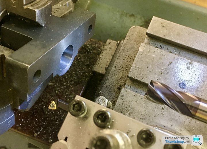
Just identifying it for you. Martin C Ah OK thanks. Back to the basics - one thing I'm pretty sure isn't correct is the way I held the block in the chuck - if you look at the image below: I set it up by temporariy putting parallels between the 'wings' and the ends of the 2 opposed jaws. Once tapped back into contact, I removed the parallels and centered the piece with the centering rod. I then put the DTI on the face next to the existing bore to check it was normal to the rotation axis. So in other words, the part wasn't positively located along it's axis apart from friction with the jaws. If I put spacer pieces behind, they woul'd probably have flown out when spun. If I'd have put excess pressure on the tool, the part would probably have moved back, or at least out of true. Any advice? Thanks. |
| Martin Connelly | 28/05/2020 14:39:29 |
2549 forum posts 235 photos | What I can do with my lathe is put a collet in the spindle and put the chuck over it. The collet drawbar is hollow so I can put long bars in if required. I often do this with something like a 19mm/3/4" tube. Once the tube is gripped by the collet I skim the face to make sure it is running true then I can use it as a fixed backstop or as a flat face for setting parts to. If I had the need I would thread the end of a bar, make a bush to go on the thread and machine that flat in place to get a larger diameter than the collets hold or the chuck bore accepts. Martin C |
| Dr_GMJN | 28/05/2020 15:00:08 |
1602 forum posts | Posted by Martin Connelly on 28/05/2020 14:39:29:
What I can do with my lathe is put a collet in the spindle and put the chuck over it. The collet drawbar is hollow so I can put long bars in if required. I often do this with something like a 19mm/3/4" tube. Once the tube is gripped by the collet I skim the face to make sure it is running true then I can use it as a fixed backstop or as a flat face for setting parts to. If I had the need I would thread the end of a bar, make a bush to go on the thread and machine that flat in place to get a larger diameter than the collets hold or the chuck bore accepts. Martin C Right, thanks. I don't have a collet like that - with a drawbar - for the lathe. I wonder if I could machine a disc to go in the centre register of the chuck though? The part would hold it in place axially, and the register would stop it falling out sideways. I'll have a look later. |
| Martin Connelly | 28/05/2020 15:25:44 |
2549 forum posts 235 photos | Have you seen this thread? I had to go back a few pages to find it. Martin C |


Please login to post a reply.
Magazine Locator
Want the latest issue of Model Engineer or Model Engineers' Workshop? Use our magazine locator links to find your nearest stockist!
Sign up to our Newsletter
Sign up to our newsletter and get a free digital issue.
You can unsubscribe at anytime. View our privacy policy at www.mortons.co.uk/privacy
Latest Forum Posts
- hemingway ball turner
04/07/2025 14:40:26 - *Oct 2023: FORUM MIGRATION TIMELINE*
05/10/2023 07:57:11 - Making ER11 collet chuck
05/10/2023 07:56:24 - What did you do today? 2023
05/10/2023 07:25:01 - Orrery
05/10/2023 06:00:41 - Wera hand-tools
05/10/2023 05:47:07 - New member
05/10/2023 04:40:11 - Problems with external pot on at1 vfd
05/10/2023 00:06:32 - Drain plug
04/10/2023 23:36:17 - digi phase converter for 10 machines.....
04/10/2023 23:13:48 - More Latest Posts...
- View All Topics
Support Our Partners


Shopping Partners
Subscription Offer

Latest "For Sale" Ads
- Reeves** - Rebuilt Royal Scot by Martin Evans
by John Broughton
£300.00 - BRITANNIA 5" GAUGE James Perrier
by Jon Seabright 1
£2,500.00 - Drill Grinder - for restoration
by Nigel Graham 2
£0.00 - WARCO WM18 MILLING MACHINE
by Alex Chudley
£1,200.00 - MYFORD SUPER 7 LATHE
by Alex Chudley
£2,000.00 - More "For Sale" Ads...
Latest "Wanted" Ads
- D1-3 backplate
by Michael Horley
Price Not Specified - fixed steady for a Colchester bantam mark1 800
by George Jervis
Price Not Specified - lbsc pansy
by JACK SIDEBOTHAM
Price Not Specified - Pratt Burnerd multifit chuck key.
by Tim Riome
Price Not Specified - BANDSAW BLADE WELDER
by HUGH
Price Not Specified - More "Wanted" Ads...
Get In Touch!
Do you want to contact the Model Engineer and Model Engineers' Workshop team?
You can contact us by phone, mail or email about the magazines including becoming a contributor, submitting reader's letters or making queries about articles. You can also get in touch about this website, advertising or other general issues.
Click THIS LINK for full contact details.
For subscription issues please see THIS LINK.
Digital Back Issues


Donate

 Register
 Log-in
Model Engineer Magazine
- Percival Marshall
- M.E. History
- LittleLEC
- M.E. Clock

ME Workshop
- An Adcock
- & Shipley
- Horizontal
- Mill

Subscribe Now
- Great savings
- Delivered to your door

Pre-order your copy!
- Delivered to your doorstep!
- Free UK delivery!
All Forum Topics > Work In Progress and completed items > Stuart 10V Build Log - Complete Beginner...