Forum sponsored by:

Stuart Twin Victoria (Princess Royal) Mill Engine
| Ramon Wilson | 25/08/2022 10:34:17 |
 1655 forum posts 617 photos | I would agree to a degree with Jason here Doc as I didn't take on board that the steps were so shallow. Even so there is no need to undercut unless something is going to sit firmly against the shoulder in question - money and choice are the keywords but an exposed undercut in a shaft for no practical reason is not going to look right - well not in my book On the other hand if the shoulder is to locate something then yes an undercut would be needed if the step is minimal. Though I have quite a few Dickson toolholders I don't have an extended version - just using a longer piece of HSS is enough if the occasion warrants it. To my mind the tailstock clearance on the top slide is one area where Myford could have made a big improvement to the lathe had they chose to do so. Doesn't the Warco have that Jason? |
| Ramon Wilson | 25/08/2022 11:31:52 |
1655 forum posts 617 photos | As an addition to the last post if you take a look at this image again you will see that where there is need for location - Crank web and bearing seats - the radius is reduced to virtually nothing and the mating parts lightly chamfered to accommodate any slight radius in the very corner - no undercuts required.
All other shoulders have a radius - why would there be a need to undercut such and besides it will probably lead to comments such as "What are those undercuts for ?" if you do - horses for course etc Best - R Edited By Ramon Wilson on 25/08/2022 11:32:33 |
| JasonB | 25/08/2022 11:46:08 |
 25215 forum posts 3105 photos 1 articles | Doc's earlier sections through the various parts on the shaft do show them locating against the shoulders though probably only needed for his eccentrics and not the bearings as shown, even then it's debateable if the eccentrics really need it. EDIT the steps on your crankshaft shown above while I was typing are a lot more than 0.5mm so there is still good location even with internal radius and chamfers of the mating parts. I do a lot of my work with a 0.2mm tip radius insert so apart from threads seldom add an undercut but Doc's tool has a bigger radius The warco tailstock is not symmetrical when you look from the end unlike the Myford as the vertical part is set towards the rear of the machine so you do get better clearance for the top slide which goes almost under the barrel. I find it's more of a case of clearing the revolving ctr than the tailstock . It could do with a bit more overhang of the casting at the nose as there is a lot further to reach when working on shorter items due to the much wider topslide.
Edited By JasonB on 25/08/2022 11:53:43 |
| Ramon Wilson | 25/08/2022 12:22:53 |
1655 forum posts 617 photos | Yes I thought that was how the Warco tailstock was relieved, just like on a Colchester 2000 (and many others no doubt) As you say though the live centre major diameter can be an issue at times. I have a very nice but larger diameter Jones and Shipman that's rarely used due to that situation so my 'turn to' one most of the time is one of those 'Skoda' centres (remember that constant advert in ME ?) bought years ago that still does the business but I recently purchased one of those small diameter ones from Arc - a real asset for sure as it's been well used since. The only point that actually requires a step for location are the two faces between bearings and that for the crank webs. As you infer it's much better to be able to position the eccentrics from a lining up point of view so allowing that ability is much the better option
|
| JasonB | 25/08/2022 12:29:34 |
25215 forum posts 3105 photos 1 articles | Interesting thoughts about bearing location there. As this is a twin with a crank either end just outside the bearings I would have thought that the large bearing surface between crank arm and bearing flange would be best to locate the shaft from sideways movement. If the inner step on the shaft were to be used on Doc's model there is very little area for the side of the bearing to run against and could possible wear quicker than if using the whole side of the bearing to locate things. |
| Ramon Wilson | 25/08/2022 13:17:43 |
1655 forum posts 617 photos | I suppose that depends on how the bearings are finished off - I don't see this as an issue as you can see the bearing face on the Corliss is just that circle on both sides so the bearing face area is the same either on crank or shaft. The important thing is that there is clearance on one side or the other so it doesn't matter which side as long as the crankshaft is captive and not allowed to float. Trying to bring both faces on each bearing to a smooth running fit risks the possibility of a tight fit but then the bearing could be tweaked on the faces if so. This really is a choice thing I guess but I prefer to use the inner faces to keep the shaft in place axially - after all if you don't have a second crank but a pedestal then that's all there is. As you say Jason, all interesting thoughts throughout a build such as this especially from Doc's perspective Regards - R
|
| Dr_GMJN | 25/08/2022 16:19:13 |
 1602 forum posts | Understood about the need for a bit of end float on the bearings. I've modified the cylindrical lengths to give about 0.25mm float, which can be adjusted to zero by snugging the eccentric against the bearing face, the eccentric subsequently being secured with grub screws (the fitting of which has been previously covered by one of Ramon's posts): |
| JasonB | 25/08/2022 16:45:01 |
25215 forum posts 3105 photos 1 articles | Good Loctite joint should be strong enough, there is plenty of area. Check your eccentric drawing, there is a small raised boss on the opposite side to the main one Edited By JasonB on 25/08/2022 16:47:19 |
| Dr_GMJN | 25/08/2022 16:52:23 |
1602 forum posts | Yes, bosses on both sides of the eccentric with blend radii to the disc. Drawing just represents the overall width of the part to get the shaft dimensions about right. |
| Ramon Wilson | 25/08/2022 17:42:45 |
1655 forum posts 617 photos | Doc, I can't think of a single full size crankshaft with an axial pin to prevent the crank moving but there are the odd few that have a tight fitting axial key. As far as I'm aware all full size engines of the size you are replicating would have had the crank shrunk on so a key is unnecessary. Loctite 638 or similar replicates this with ease. The crankpin(s) is just Loctited but I make the last mil or so on the spigot a tight fit in the crank web hole Apart from one, all the cranks I have made so far then have been Loctited and pinned but with a radial pin going in from the outer diameter of the crank through the shaft and just into the crank opposite. This gives the strongest shear but with only one face to disguise the pin on and a curved one at that - much easier to do that than a flat one if using the likely file and emery paper. The odd one was an attempt at shrinking on but it was well and truly stuck before reaching it's location - never attempted it again. Crankpins are never pinned but I do make the last mil or so a tight fit as the crankpin reaches its location That said the shaft and pins are both pinned on this latest one, mainly to assist in reinforcing the shaft as a whole, a 2.5mm pin if my memory serves right. Getting the pin to be invisible is a bit of an art if the crank is a finished item but easy enough if gone about the right way - that can be covered when you get to it. You can just get a hint of it on the upper surface on the right
There's nothing wrong with using the eccentric face as a wear surface just that the eccentric position is then committed.
Just realised I have to go out tonight, I need to get a grip - back later perhaps R Edited By Ramon Wilson on 25/08/2022 17:45:20 |
| Dr_GMJN | 26/08/2022 10:00:42 |
1602 forum posts | Re-worked the shaft drawing slightly, to revise the step lengths to give about 0.25mm float for bearing adjustment. I've also removed the undercut from the first steps adjacent to the eccentrics, since they're no longer needed (nothing abutts them). *ETA I guess I could also eliminate the undercuts at the inner ends of the bearing steps, since they no longer abutt the bearing faces. Would just need a decent chamfer or radius on the inside of the bearing bore? Edited By Dr_GMJN on 26/08/2022 10:02:24 |
| JasonB | 26/08/2022 10:13:46 |
25215 forum posts 3105 photos 1 articles | I don't think anyone else looking at the engine will see that slight gap so not worth worrying about |
| Ramon Wilson | 26/08/2022 11:01:21 |
1655 forum posts 617 photos | Posted by Dr_GMJN on 26/08/2022 10:00:42:
Edited By Dr_GMJN on 26/08/2022 10:02:24 Looks like you've mastered that then Doc |
| Dr_GMJN | 28/08/2022 00:27:06 |
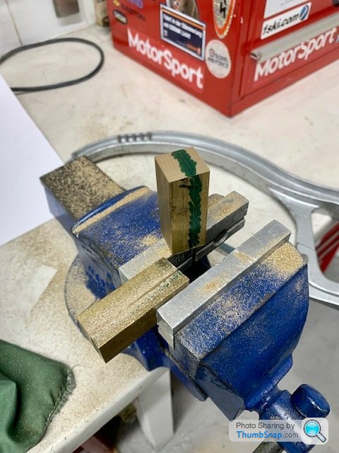
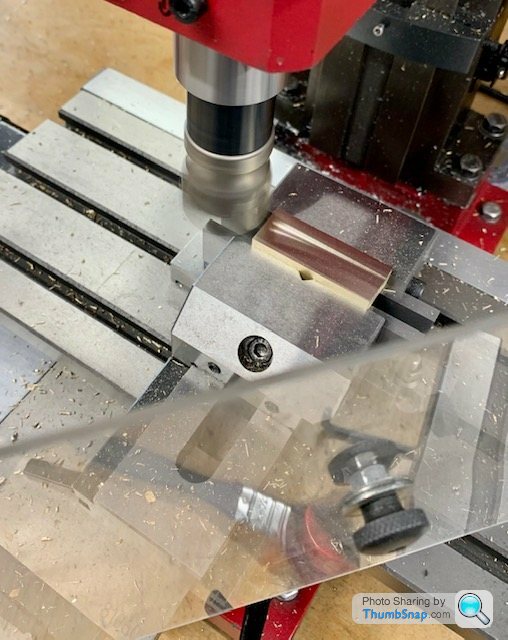
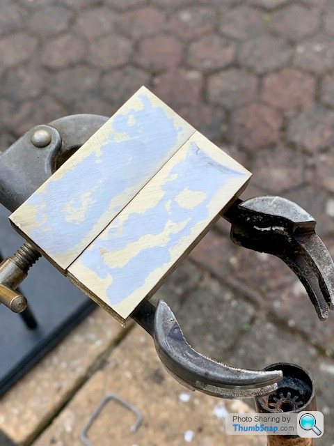
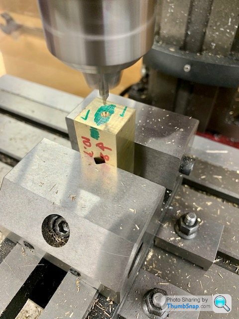
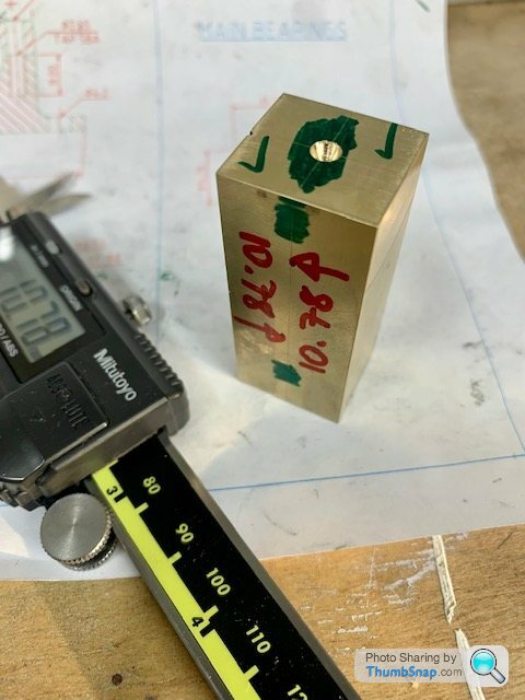
1602 forum posts | Didn't have much workshop time today, so prepared material for the split main bearings.
One question regarding this: I assume that if this single bar is for both bearings, then I bore all the way through (in order to be able to get the journal lengths fully engaged beyond the crank spigot), periodically checking fit on the shaft? Once parted-off for the first bearing, I'd double-check for fit on the other journal? I assume that the bore will taper slightly, so, assuming both journals are identical diameter, the second bore might need a spring pass or perhaps a few? |
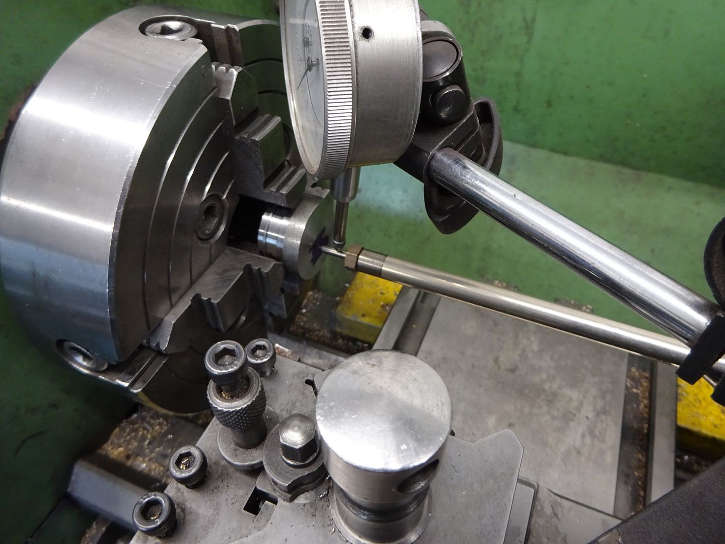
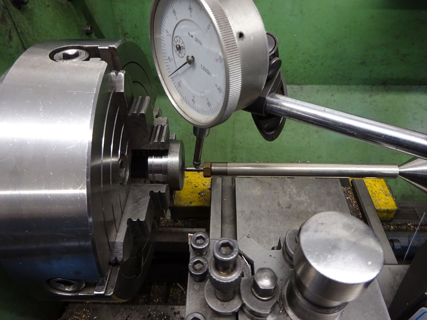
| JasonB | 28/08/2022 07:08:03 |
25215 forum posts 3105 photos 1 articles | You can put the dti on your sprung guide and clock the movement of the ctr hole which is how I usually do it. Back end of the guide wants to be free
|
| Dr_GMJN | 28/08/2022 09:49:31 |
1602 forum posts | Thanks Jason, yes that what I meant. I’m not sure what you mean by back end wants to be free though? |
| JasonB | 28/08/2022 10:10:50 |
25215 forum posts 3105 photos 1 articles | Don't hold it in the tailstock chuck, mine is free to move about as it is supported with a ctr. Though a pointed long length of say 3/16" rod would flex so could be held rigidly. |
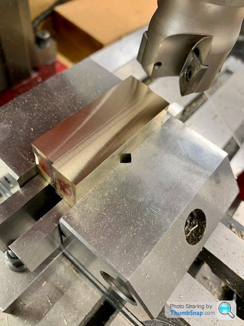
| Dr_GMJN | 28/08/2022 16:30:50 |
1602 forum posts | Hmmm bit of a rubbish day on this, with little to show for a lot of effort. Same old story when turning steel - poor surface finish, plus it’s inconsistent. Also, for the lengths and step sizes I need, my HSS tool is too big and clunky - undercut lengths are huge. It didn’t give a very good finish on the actual shaft material either: Also realised my drawing is no good, since stepping the shaft has given me a middle section bigger than the stock 1/2” material I got. I could use the 7/16” stock, but as discussed before, it’s slightly undersized, and gives 0.002” runout after centering. It looks pretty thin before skimming it to give no runout. The step sizes also become very small. I’ll probably re-draw it for the 1/2” stuff, but ending at 12.5mm or something. |
| JasonB | 28/08/2022 16:42:46 |
25215 forum posts 3105 photos 1 articles | Are you honing the HSS tool after grinding, just a rub in a diamond stone should produce a better cutting edge. Even with the carbide a small amount of cutting fluid will improve finish Not sure what size ctr drill you are using but I use a BS-0 which is 1/8" shank and a very small pilot, you only need go in a little way with the 60deg part not full depth Treat yourself to some 9/16" or 14-15mm bar and get some decent steps, the flywheel hub can take the extra size. |
| Dr_GMJN | 28/08/2022 17:13:26 |
1602 forum posts | Thanks Jason. I’ll re-draw for 1/2” and treat it as a machining trial. Im not really sure what you mean by ‘honing’. I’ve got a large ‘oil stone’ for chisels, and some ARC diamond laps, but it seems like whenever I try to clean up a cutting edge, I actually get the angle slightly wrong and end up - probably - dulling the edge. I find it difficult to judge whether the abrasives are actually doing anything, often feels like they’re just skimming across the surface without touching it. The only way I can do it is by trial and error - usually error, and…it just brings me one step closer to packing up the tools and doing something else, when I really want to make progress. |
.jpg")


.jpg")


Please login to post a reply.
Magazine Locator
Want the latest issue of Model Engineer or Model Engineers' Workshop? Use our magazine locator links to find your nearest stockist!
Sign up to our Newsletter
Sign up to our newsletter and get a free digital issue.
You can unsubscribe at anytime. View our privacy policy at www.mortons.co.uk/privacy
Latest Forum Posts
- hemingway ball turner
04/07/2025 14:40:26 - *Oct 2023: FORUM MIGRATION TIMELINE*
05/10/2023 07:57:11 - Making ER11 collet chuck
05/10/2023 07:56:24 - What did you do today? 2023
05/10/2023 07:25:01 - Orrery
05/10/2023 06:00:41 - Wera hand-tools
05/10/2023 05:47:07 - New member
05/10/2023 04:40:11 - Problems with external pot on at1 vfd
05/10/2023 00:06:32 - Drain plug
04/10/2023 23:36:17 - digi phase converter for 10 machines.....
04/10/2023 23:13:48 - More Latest Posts...
- View All Topics
Support Our Partners


Shopping Partners
Subscription Offer

Latest "For Sale" Ads
- Reeves** - Rebuilt Royal Scot by Martin Evans
by John Broughton
£300.00 - BRITANNIA 5" GAUGE James Perrier
by Jon Seabright 1
£2,500.00 - Drill Grinder - for restoration
by Nigel Graham 2
£0.00 - WARCO WM18 MILLING MACHINE
by Alex Chudley
£1,200.00 - MYFORD SUPER 7 LATHE
by Alex Chudley
£2,000.00 - More "For Sale" Ads...
Latest "Wanted" Ads
- D1-3 backplate
by Michael Horley
Price Not Specified - fixed steady for a Colchester bantam mark1 800
by George Jervis
Price Not Specified - lbsc pansy
by JACK SIDEBOTHAM
Price Not Specified - Pratt Burnerd multifit chuck key.
by Tim Riome
Price Not Specified - BANDSAW BLADE WELDER
by HUGH
Price Not Specified - More "Wanted" Ads...
Get In Touch!
Do you want to contact the Model Engineer and Model Engineers' Workshop team?
You can contact us by phone, mail or email about the magazines including becoming a contributor, submitting reader's letters or making queries about articles. You can also get in touch about this website, advertising or other general issues.
Click THIS LINK for full contact details.
For subscription issues please see THIS LINK.
Digital Back Issues


Donate

 Register
 Log-in
Model Engineer Magazine
- Percival Marshall
- M.E. History
- LittleLEC
- M.E. Clock

ME Workshop
- An Adcock
- & Shipley
- Horizontal
- Mill

Subscribe Now
- Great savings
- Delivered to your door

Pre-order your copy!
- Delivered to your doorstep!
- Free UK delivery!
All Forum Topics > Work In Progress and completed items > Stuart Twin Victoria (Princess Royal) Mill Engine