Forum sponsored by:

Stuart Twin Victoria (Princess Royal) Mill Engine
| Dr_GMJN | 09/08/2022 23:11:43 |
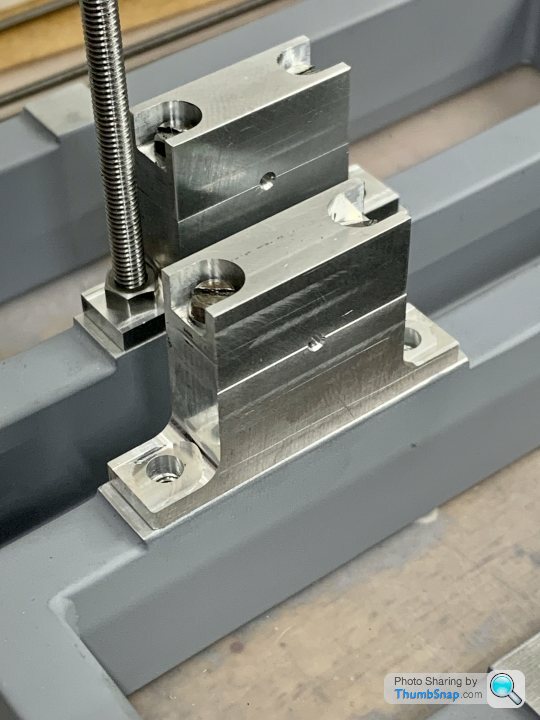
 1602 forum posts | Bit of progress - milled the sides and counterbores. Seemed to work ok, more room for everything: |
| Dr_GMJN | 09/08/2022 23:53:09 |
1602 forum posts | Guys - What is the issue with the ‘fake’ taper key causing flywheel wobble? As Jason said, the thick part of the wedge will just contact the top of the flywheel keyway along a line, without any outward load being applied, and the grub screw (which is angled to stop the key coming out) will stop lateral movement. The taper keys will still have a rectangular shear area, but approximately triangular contact faces. If I make a tool from silver steel, can’t I machine it square (obviously with a cutting edge), centre drill it in the 4-jaw, and then harden it? I can then use the drilling to align the tool to a centre in the lathe spindle, ensuring it’s dead on the centreline of the hub. Then cut the key, measure it’s width and replicate the width on the shaft by milling. Then make the keys to suit. It’s not like me to simplify things, but I can’t see any huge issues? * (* disclaimer - I’ve never done this before)
So what’s the issue? |
| JasonB | 10/08/2022 07:14:14 |
 25215 forum posts 3105 photos 1 articles | There should not be much wrong with it as a bit of looking at the article shows, Ramon and myself were suggesting it would be harder to use a tapered key in a tapered keyway. A taper key against a tapered keyway will act like a folding wedge and move the flywheel radially with no tilt but a minute amount of axial offset which will depend on fit of shaft in the bore, lets say half a thou at the most (should be a lot less) which you would not see the eccentricity of. Of you have a tapered key against a plain keyway it will tend to push the side of the flywheel where the thick end of the keyway is away from the shaft, lets say the same half a thou. which with a bit of trig is probably about 5thou offset at the rim so 10thou total wobble which you will see. As I said the grubscrew shown will have some jacking action as well as retaining the key so you should be able to reduce that wobble quite a bit. The angle of the grub screw is actually so you can physically drill and tap the hole as you could not do it square on very easily without extending drill and tap but the closer to right angles to the shaft the better. Yes you could mill silver steel or just use a 1/8" square HSS tool blank which would be even simpler with the added advantage that the flat face being gripped in the holder will ensure the cutting face is square on. Doing the slots with a 3/32" or 3mm cutter and then taking a bit more off the sides would get them to a matching width,
|
| Ramon Wilson | 10/08/2022 08:11:18 |
 1655 forum posts 617 photos | Paul, A tapered key mating with a tapered slot will I agree not influence the plane of the flywheel but as previously said a tapered key in a parallel slot fitted tight enough sufficient to locate the flywheel firmly (and at one end only) will influence the flywheel rim if there is the slightest slack in the bore to shaft make up. If tapered keys were used in such a fashion three or four would be used. Jason's thought are the same as mine here it takes very little difference at the shaft to put the rim out of kilter perfectly witnessed when running of course. Broaching - again, as already said, is fine if you have the broaches and the means to apply them. Totally agree, if you make a broach guide at 120 degrees then the angular accuracy is readily attained. That is the way I broached this wheel. Though I made the guide at home I broached it using the broaches and broaching press at work. Not quite the same when you only have an ML7 to use. Apologies for the bold - the means to underline text would be much better!
Doc, As mentioned previously, yes you can machine the tool bit from Sil St and it should do the job fine but just harden it, I wouldn't temper it. The tool needs backing off on all sides - particularly the width otherwise it will rub and wear as the slot deepens producing a key way with tapered sides! Definitely not what you want. This op on a lathe is one that has to be done slowly, even with a one thou cut, the force require is considerable. Again on an ML7 with that small saddle wheel as a driving force a huge difference from a Marlco broaching set up - and a larger lathe of course. The wider the key the more force required. Jason's idea of roughing first is one way of getting round this but to my mind at no more than 3mm wide it's best done in one hit. The tool/ toolbit holder needs to be short and reasonably substantial if flexing is not to occur. That will produce a tapered key way of unknown angle. It’s not like me to simplify things, but I can’t see any huge issues? * (* disclaimer - I’ve never done this before) This is not a difficult op Doc but it has many potentials for slight error that will be only too obvious when fitting the key(s) |
| Dr_GMJN | 10/08/2022 08:17:30 |
1602 forum posts | Thanks Jason. I understand that a tapered key in a flat keyway would wedge the flywheel out at one end, but only if you apply any axial force to it. Im assuming the key is tapped into the hub until the taper just touches the edge of the hub (the line contact I mentioned) rather than having any load on it. The grub screw holds everything tight. Even the parallel key option mentioned has a grub screw for retention, which when tightened might displace the hub slightly, so I can’t see any advantage there? Understood about the angled grub screw hole. I don’t know why a parallel key with a ‘head’ wasn’t specified on the plans, since it seems purely a ‘dummy’ feature, added for a bit of realism? The taper is never seen and appears to serve no function?
Edited By Dr_GMJN on 10/08/2022 08:19:35 |
| Ramon Wilson | 10/08/2022 09:27:59 |
1655 forum posts 617 photos |
A wedge type key that you show would be used to apply radial force to hold the flywheel in place hence the gib or head to enable extraction. It would likely be used on the kind of flywheel you wish to represent in three's or four's in order, as Jason has already pointed out, to apply equal radial force and to eliminate tilting as already said - 'staking a flywheel' I believe, is the correct terminology but this is usually when the flywheel has clearance to allow the tapers to trim any slight misalignment the wheel may have as well as retain it Unless the slot is accessible at an open end, ie the end face of a stepped shaft, this is not the type of key to use in a slot cut in the shaft. Unless it has a matching taper as Paul has pointed out, it's short diminishing surface area is the only driving force. Such keys would usually bear directly on the shaft surface - usually on flat faces and usually from both sides of the wheel. A sunken key on the other hand can be across the full width of the wheel and is captive by the slot - it gives full drive and only the smallest grub screw is require to prevent lateral movement of the wheel. If it's made smaller than the width of the flywheel then you could put dummy keys in to represent gib keys I'm assuming you didn't see my previous post re the cutter?
Edited By Ramon Wilson on 10/08/2022 09:28:14 |
| JasonB | 10/08/2022 10:11:57 |
25215 forum posts 3105 photos 1 articles | Hold On, hold on! I just read a bit more of TC article, the grab screws are on the HEAD side of the hub so won't do any jacking. If we assume tapered keyways in the flywheel are out for the Doc then what about fitting shorter tapered keys in from BOTH sides. If sized so that the taper just engages with about 1/4 to go then a final drive will see them go in a further 1/8" leaving a suitable gap for removal. As the wedging action will be at both sides of the flywheel it should be equal and only induce an minute eccentricity which the eye can't see.
|
| Ramon Wilson | 10/08/2022 10:38:17 |
1655 forum posts 617 photos | Well isn't that what I said in the first instance Jason I'm not familiar with TC article and not sure what you mean by the HEAD side of the wheel but lets just get back to basics. We need to fit a flywheel to a shaft on a representation of a large stationary engine. Now we can do it to absolute scale on one hand or reduce it to the most simplistic grub screw drive on the other. Somewhere we need to meet in the middle with a fair workable compromise. We need to drive the flywheel round by the crankshaft so need a basic means to attach the two to do so and a simple straight key is the easiest option (setting aside the need for two at 120 degrees for the moment) If - the keys are made as shown then the ability to slide them in from the end has to be there - that means slots in the shaft where they shouldn't be - for this representation. If Doc really wants to show keys of this nature then it would be best to have them without slotting the shaft - ie as full size, on flats - or live with extended keyways in order to do so. Obviously if not on flats these would be dummies and would soon lose their grip so a means to drive the wheel has to be there - one slotted sunken key out of sight and two or more dummy keys to hide it - compromise complete. There would not be the need to do the second slot at an exact 120 degrees to match anything if so. The other alternative would be a simple discreet but more adequate grub screw that provides the drive but as said that defeats the object Doc picks up on both our points about the single point contact - just touching so not influencing the wheel to any degree. That's not a satisfactory drive to me - if the grub screw is doing that then the keys a dummy anyway I guess I'm repeating myself so I'll shut up now - flogging and dead horses spring to mind Edited By Ramon Wilson on 10/08/2022 10:49:57 |
| JasonB | 10/08/2022 11:19:05 |
25215 forum posts 3105 photos 1 articles | Ramon this should show what I meant by "head end" the grub screw is towards the head of the key so will only add further tilting force, had it been at the narrow end of the key it may have counteracted and tilt induced by the key.
I think our thoughts are basically the same, For what the Doc can do with his kit: Single keyway in the shaft which I would have with stopped ends not extending beyond largest dia. Single parallel keyway in flywheel as it's easy to cut Parallel key with a head for looks which will provide the drive. Small M3 grub screw at each end of this slot to take up any slack in the fit of the flywheel on the shaft and also stop the flywheel moving along the shaft. Screws to bear on key so you don't chew up the shaft Optional additional keys and keyways for looks only is desired
Edited By JasonB on 10/08/2022 11:25:11 |
| Dr_GMJN | 10/08/2022 12:40:19 |
1602 forum posts | Posted by Ramon Wilson on 10/08/2022 09:27:59:
I'm assuming you didn't see my previous post re the cutter?
Actually no I didn't see it - as sometimes seems to happen, It appeared after I'd posted this morning - so it may have appeared I've ignored something, but in fact I never saw it until just now. Probably you posted it as I was writing something. |
| Hopper | 10/08/2022 12:47:21 |
 7881 forum posts 397 photos | When I made my similarly sized model mill engine I just used a grub screw to hold the flywheel on the shaft and no apparent runout. I did make the reamed hole in the middle a good tight fit on the shaft so it could not cant. I can't see a decorative key not driven in hard would make any more difference than the jacking effect of just a grub screw? |
| Dr_GMJN | 10/08/2022 12:57:08 |
1602 forum posts | Ha ha I'm totally confused by all this. Why is there any jacking using a tapered key, when the tapered part of the key never touches the hub? Ramon - why is a tapered key secured with a grub screw a dummy? The driving torque is being transferred entirely by the resistance to shear of the key, albeit over a reduced area due to the taper. The grub screw isn't taking any shear or driving torque whatsoever, it's only there to stop the key from moving relative to the hub. I totally get the wedging action of the tapered key in a tapered slot being used to avoid putting the flywheel out of plane, but that principle is (I think) totally redundant in how this model was designed. The tapered key actually doesn't need to be tapered at all - as far as I can see, it's a completely un-necessary red herring in terms of function for this model, although I could imagine it may be a bit easier to fit than a parallel key. Jason - I can't put wedges in from both ends of the hub, because there's no gap on the governor pulley side. I can see that having two tapered keys would eliminate tilt, but only if they were tapped into the hub enough that they would wedge the hub out in the first place. But that's not the case, so....I'm lost.
|
| Dr_GMJN | 10/08/2022 12:57:54 |
1602 forum posts | Posted by Hopper on 10/08/2022 12:47:21:
I can't see a decorative key not driven in hard would make any more difference than the jacking effect of just a grub screw?
Same here. I can't see the issue. |
| Ramon Wilson | 10/08/2022 13:20:12 |
1655 forum posts 617 photos | I really must be getting old! I just checked the Waller, Double Diagonal (which is as far as I am aware a true scale model of the original) and the Mc'Onie. All have headed keys as shown in your sketch Doc but I know I made them parallel, slightly over thick then filed them with a very slow taper so they bind tight - they are all of course driven from the ends of the respective shafts
(This shows the drive gear but the flywheel is done in the same fashion).
There is nothing wrong with this method but you were saying that the key you have will only stop where it touches and then be held by a grub screw. The small area of the key will soon wear from the inertia of starting and you will have a rocking movement develop quite quickly - only my opinion of course but that's how I see it and it's there for what it's worth.
As Hopper suggests there is absolutely nothing wrong from a practical point of view with using a simple grub screw either - it's just that I was under the impression you were going to make this engine as similar to an original one - in which case grub screw drive (Oh we do need the facility to underline at times) was not in my thinking Not trying to confuse you Doc , certainly not intentionally for sure R |
| JasonB | 10/08/2022 14:04:24 |
25215 forum posts 3105 photos 1 articles | Posted by Dr_GMJN on 10/08/2022 12:57:08: Jason's answers in bold Ha ha I'm totally confused by all this. Why is there any jacking using a tapered key, when the tapered part of the key never touches the hub? The key touches at one edge of the hub, see the ringed area on my sketch in previous post as said earlier this can tilt the flywheel particularly if the hole is a bit loose. A grubscrew in the same situation will also tilt a poor fitting flywheel Ramon - why is a tapered key secured with a grub screw a dummy? The driving torque is being transferred entirely by the resistance to shear of the key, albeit over a reduced area due to the taper. The grub screw isn't taking any shear or driving torque whatsoever, it's only there to stop the key from moving relative to the hub. A properly fitted tapered key into a tapered keyway DOES NOT need a grubscrew. The friction of the two tapered faces hold the key in place and neither that or the flywheel can move along the shaft. Key that does not make full contact won;t hold the flywheel tightly and it will soon come loose I totally get the wedging action of the tapered key in a tapered slot being used to avoid putting the flywheel out of plane, but that principle is (I think) totally redundant in how this model was designed. The tapered key actually doesn't need to be tapered at all - as far as I can see, it's a completely un-necessary red herring in terms of function for this model, although I could imagine it may be a bit easier to fit than a parallel key. Hence my last image of a parallel key, the taper is not needed if a screw is used Jason - I can't put wedges in from both ends of the hub, because there's no gap on the governor pulley side. I can see that having two tapered keys would eliminate tilt, but only if they were tapped into the hub enough that they would wedge the hub out in the first place. But that's not the case, so....I'm lost. It can be done and I have done it but not worth going there as it will just complicate things I could post photos of 20+ models I've made with proper keys and keyways but again not much point
Edited By JasonB on 10/08/2022 14:05:28 |
| Ramon Wilson | 10/08/2022 14:53:08 |
1655 forum posts 617 photos | I really do think we are all confusing each other on this one I thought we had already established that a tapered key in a matching tapered slot is totally different kettle of fish and not relevant to this model - and no, its should not require a grub screw to hold it in position
From the outset I said the object is to DRIVE the flywheel by a key - I agree you will be doing this with Docs drawn key but only by a marginal area. That marginal area, as previously stated, will soon wear in my opinion with the starting torque inertia and lead to rocking. It is not the correct way to fit such a key. I did not say the key IS a dummy but that it could be - with the drive taken up with a hidden, sunken, key within the width of the flywheel - a far more substantial means to drive the wheel. The headed keys could then be dummies I haven't built twenty models but those I have I have tried to replicate full size practice where possible. That adherence is not needed, it's certainly not a necessity and I'm not advocating it should be a consideration but the means of drive should be sufficient for the task. I don't consider this so I used the word compromise and this is what I attempt to do - not always possible of course but I do try. An example is the Marine Compound crankshaft - the coupling and flywheel mount are keyed with sunken keys - full size there would be no flywheel and the coupling would, in all probability, be forged in situ with the crankshaft. Eccentrics would likely be split to enable removal. On this model eccentrics are solid and both coupling and flywheel mount will have a very small grub screw to retain them longitudinally but will not play a part as such in the drive Docs question at the outset was about tapered keys in a parallel slot (though at first I did think he meant a tapered slot) - I'd like to think that I've tried to answer and show that as best I can Best - R
|
| JasonB | 10/08/2022 15:04:01 |
25215 forum posts 3105 photos 1 articles | Posted by Ramon Wilson on 10/08/2022 14:53:08:
From the outset I said the object is to DRIVE the flywheel by a key - I agree you will be doing this with Docs drawn key but only by a marginal area. That marginal area, as previously stated, will soon wear in my opinion with the starting torque inertia and lead to rocking. It is not the correct way to fit such a key. Not sure I follow that Ramon. if by drive you mean th erotational load from the shaft into the flywheel then the tapered key into the parallel keyways will transmit maybe 99% of the load that a plain parallel key would as there is almost full contact with the side of the key and the keyway in the flywheel. The only thing it doe snot do is stop the flywheel coming loose and sliding ALONG the shaft The whole top half of the key in the image below is driving against the side of the flywheel keyway.
|
| Ramon Wilson | 10/08/2022 15:31:23 |
1655 forum posts 617 photos | Yes I agree Jason but I said Doc's key as drawn - marginal at best. What you show in your drawing here is a much longer shallow taper key with a considerable length of 'drive' and much improved This is just as I described in my three examples above but the taper filed on top is even shallower and the fit over a longer length very tight (radially) as well as a good fit in both slots. No matter how slow a taper it will only bear on one point of course - if over tightened be ready for that slight but possible tilt though a wide flywheel such as this that should be minimal and yes, as I said too, a discreet grub screw is all that's required to prevent lateral movement along the shaft - something despite the eight keys I did on the Corliss flywheel
The two keys at 120 degrees as recommended will of course give a three point contact - personally if I were to be fitting multiple keys I would be milling three or four flats on the shaft I found this pic of the 'staked' flywheel on the Corliss in the Forncett museum - a bit dark but you can see the annular gap and the four keys if you click on it
BTW how do you insert or extract the gib key from the sunken slot and flywheel in your first image (previous post) if such a long taper is machined on
Edited By Ramon Wilson on 10/08/2022 15:34:19 |
| JasonB | 10/08/2022 16:52:04 |
25215 forum posts 3105 photos 1 articles | Posted by Ramon Wilson on 10/08/2022 15:31:23:
Yes I agree Jason but I said Doc's key as drawn - marginal at best. What you show in your drawing here is a much longer shallow taper key with a considerable length of 'drive' and much improved Doc reproduced the key from the drawings, no actual length given but it does say "length to suit" I would take that as just short of full width of the double hub so it does not hit the pulley. Scaling in CAD it comes out about 1.75" long overall. The pair of hubs total 1.75" wide so about right This is it drawn with both at 1.75" long, does not look bad engagement to me, extra 1/8" length on the key would be all it could take.
|
| JasonB | 10/08/2022 17:20:47 |
25215 forum posts 3105 photos 1 articles | For flywheels I have done with a tapered key in a stopped keyway mid way along a shaft there are two options. The small amount of extra length in the shaft keyway is usually enough to prize the key out enough to break the taper. Folding steel wedges (I use one side of my drill chuck removal wedges) will go between head and side of flywheel or as mentioned earlier tow flat bladed screwdrivers have a similar effect. The other way is to hold the flywheel in your left hand and hit the end of the shaft with a nylon faced hammer in your right which will usually break the grip of the key. This method is also the one to use with a non headed key that is the full length of the shaft keyway. The big Easton and Anderson I made was of the later type |
.jpg")


Please login to post a reply.
Magazine Locator
Want the latest issue of Model Engineer or Model Engineers' Workshop? Use our magazine locator links to find your nearest stockist!
Sign up to our Newsletter
Sign up to our newsletter and get a free digital issue.
You can unsubscribe at anytime. View our privacy policy at www.mortons.co.uk/privacy
Latest Forum Posts
- hemingway ball turner
04/07/2025 14:40:26 - *Oct 2023: FORUM MIGRATION TIMELINE*
05/10/2023 07:57:11 - Making ER11 collet chuck
05/10/2023 07:56:24 - What did you do today? 2023
05/10/2023 07:25:01 - Orrery
05/10/2023 06:00:41 - Wera hand-tools
05/10/2023 05:47:07 - New member
05/10/2023 04:40:11 - Problems with external pot on at1 vfd
05/10/2023 00:06:32 - Drain plug
04/10/2023 23:36:17 - digi phase converter for 10 machines.....
04/10/2023 23:13:48 - More Latest Posts...
- View All Topics
Support Our Partners


Shopping Partners
Subscription Offer

Latest "For Sale" Ads
- Reeves** - Rebuilt Royal Scot by Martin Evans
by John Broughton
£300.00 - BRITANNIA 5" GAUGE James Perrier
by Jon Seabright 1
£2,500.00 - Drill Grinder - for restoration
by Nigel Graham 2
£0.00 - WARCO WM18 MILLING MACHINE
by Alex Chudley
£1,200.00 - MYFORD SUPER 7 LATHE
by Alex Chudley
£2,000.00 - More "For Sale" Ads...
Latest "Wanted" Ads
- D1-3 backplate
by Michael Horley
Price Not Specified - fixed steady for a Colchester bantam mark1 800
by George Jervis
Price Not Specified - lbsc pansy
by JACK SIDEBOTHAM
Price Not Specified - Pratt Burnerd multifit chuck key.
by Tim Riome
Price Not Specified - BANDSAW BLADE WELDER
by HUGH
Price Not Specified - More "Wanted" Ads...
Get In Touch!
Do you want to contact the Model Engineer and Model Engineers' Workshop team?
You can contact us by phone, mail or email about the magazines including becoming a contributor, submitting reader's letters or making queries about articles. You can also get in touch about this website, advertising or other general issues.
Click THIS LINK for full contact details.
For subscription issues please see THIS LINK.
Digital Back Issues


Donate

 Register
 Log-in
Model Engineer Magazine
- Percival Marshall
- M.E. History
- LittleLEC
- M.E. Clock

ME Workshop
- An Adcock
- & Shipley
- Horizontal
- Mill

Subscribe Now
- Great savings
- Delivered to your door

Pre-order your copy!
- Delivered to your doorstep!
- Free UK delivery!
All Forum Topics > Work In Progress and completed items > Stuart Twin Victoria (Princess Royal) Mill Engine