Forum sponsored by:

Colchester Student Mk1 Won't Start
| Herman van der Merwe | 30/07/2020 08:58:01 |
 180 forum posts | Posted by Richard Kirkman 1 on 29/07/2020 22:56:02:

As it turns out, the yellow bearing cover replacement part that I wanted is the wrong size. The last of the 3 mounting holes doesn't line up, so i'll have to fix the old one somehow Just TIG weld the wrong hole close and drill a correct hole in the flange of the cover. Edited By Herman van der Merwe on 30/07/2020 08:58:29 |
| Richard Kirkman 1 | 30/07/2020 14:10:13 |
| 334 forum posts 799 photos | Yeah Herman, that sounds like a good idea. But I can't TIG, don't have the facilities or the practice. Plus, If I'm going to be tiging then I may well just fill up the old one and fix that instead of modifying a different one I've looked at the splash back this morning. Not great news, but problems to be solved! The mounting hole does not line up conviniently. I do not particularly want to put any holes into the headstock, and I'd like to put as few holes as possible into the splash back. I started off by removing the chuck guard which had been added at some point. I do not plan on reinstalling it. It just gets in the way. This is how the light was mounted. As far as I know, the light was attached to the back of the headstock orignally. But I don't have any holes for that, so i will try to use the splash back's mount. It needs a good clean. Everything does
Obviously not in the right orientation, but the hole size is right at least
Since all that was out of the way, I looked at the mounting of the splashback. The holes don't line up perfectly, so some work is going to need doing The pictures make it look closer, but it's probably a good half-inch away.
So I began to work on fitting the light mount together in a fashion that would work nicely.
The holes lined up, So I just had to come up with a way to get them mounted together. Luckily the blue bit had some holes for set screws, and I found some set screws the right size in the spare parts!
So I drilled out to 10.2mm then tapped M12. Cut the bolts off and put slots in (with two hacksaw blades. Thanks for the tip Phil, it worked very well)
Fully mounted. So now I just need to mount the blue bit to the splash back and the splash back to the headstock! If only the parts could have come from an identical lathe! Edited By Richard Kirkman 1 on 30/07/2020 14:12:37 |
| Herman van der Merwe | 30/07/2020 16:22:40 |
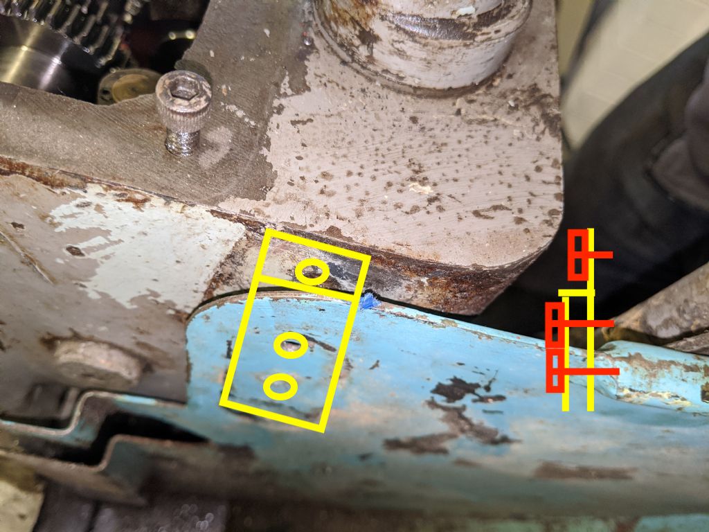
180 forum posts | Good job! For the holes that does not match up I will make a tuning fork type bracket which fits over the back plate. Put two holes in the two fork prongs and drill an extra hole above the existing plate hole. Then bolt the fork onto the plate. The stem of the fork gets a hole to match the existing hole in the headstock.
I drew with a crummy program. The bottom two bolts screws into the back plate and do not petrude. Otherwise use countersunk bolts from the back with a washer and nut on the exposed side.
Otherwise weld a plate extension to the splashing backing splashing plate.
Edited By Herman van der Merwe on 30/07/2020 16:24:16 Edited By Herman van der Merwe on 30/07/2020 16:25:11 |
| Richard Kirkman 1 | 30/07/2020 16:59:43 |
| 334 forum posts 799 photos | Good Idea Herman Although my pictures didn't quite show it very well, the back splash splash back whatever its called does go up to the hole in the headstock. So I don't need to build up any material. I'm currently thinking drill a hole and countersink for a bolt to go into the headstock hole and be flush. Then the light mount needs to attach and be flush on the rear side too. I think I'll be able to manage it. It would be easier If I had a lathe running to make some custom fittings! I'll need to measure the size of the hole in the headstock and buy some bolts. I only have metric here. Actually there may be exactly what I'm looking for in the spares box... I'll check before I go out I've just reassembled the main lathe spindle. Probably the 5th time I've done it by now, so I'm getting much better at it. It still wasn't perfect. I'll have to practice more next summer. It still took me an hour and a bit, so I need to shave another half hour off my time. |
| Phil Whitley | 30/07/2020 21:08:38 |
 1533 forum posts 147 photos | I will take a few pics of my splashback and post them up, does seem odd that it doesnt just fit straight on Phil. |
| Richard Kirkman 1 | 30/07/2020 21:46:47 |
| 334 forum posts 799 photos | All sorted now, I just decided that It needed to fit, so I've made it fit. I'm not a fan of modifying parts, but there was no other option here. Apart from get a different one from Colchester spares And very luckily the bolt I said I might have fitted perfectly Simple, I just laid out my hole spacing, drilled and countersunk. Then I cut the bolt down to the right size
I think It looks very acceptable. Not out of the ordinary too much. Only someone who knows these machines would ever notice
Then I have a plan for mounting the light mount very easily. I plan to drill down a 3/8ths bolt and tap it M6, then I can secure it on from the back flush, and it can look nice with the hex head. There should be plenty of space for it. But I need a lathe to do it accurately. So onto more assembling
I've messaged a friend about potentially tig braze filling the broken out bit of casting, but meanwhile I am just using one of the longer bolts and a washer that I made fit. This holds the gasket so it wont move, so presumably It should seal alright. Only time will tell
Then comes the question of gearing. The gear that fits on that lower shaft has 2 teeth that are partially damaged. The spare one has all its teeth intact. But, the teeth look a little bit bigger. Is this just wear and will I be okay to use it? Or should I swap all the gears on the end of the lathe to make sure they're all the same.
It's not a big difference and they seem to mesh okay
The reverse forward switch needs a mount onto the splash guard too, otherwise the whole thing is too wobbly. Not too sure how I'll do that yet as I don't want to put a hole into the splash guard and just put a bolt and nut on the other side like it was. Perhaps welding a little bit on for a mount would be good
Then, a quick question. What is this little hook/tag for?
Apart from that, I think things are shaping up. Especially once I get the other parts painted (finally) and reassembled
The ON/OFF lever feels so much more satisfying to use. I'm very happy, it was well worth the wait. Actually feels like a proper machine instead of wiggling a stick about. Imagine if your gearstick in your car was loose and moved 3 cm before it actually went anywhere. Not a good feeling Very happy with my progress today |
| Richard Kirkman 1 | 01/08/2020 20:25:21 |
| 334 forum posts 799 photos | Little progress, but something. I got the splash guard cleaned up, or at least as much as I'm cleaning it up for now Just wire brushed it and oiled it up so it hopefully won't rust any more before I paint it
Then I polished up and cleaned the new tap, since its an original one and my old one didn't seem very good. I like the new one more
I'm trying to get the other covers painted asap so I can reassemble fully and get the light mounts sorted. But I also need to take the apron to pieces to fit the new hand wheel and do some tinkering, since I seem to have messed up the threading lever when I took it off to polish it. Not good. I may have to fully disassemble it. We shall see tomorrow. |
| Herman van der Merwe | 01/08/2020 20:32:54 |
180 forum posts | You missed a spot there on the top right corner, next to the red dot. |
| Richard Kirkman 1 | 01/08/2020 21:31:22 |
| 334 forum posts 799 photos | Posted by Herman van der Merwe on 01/08/2020 20:32:54:
You missed a spot there on the top right corner, next to the red dot. Not again... Not all of our lathes can be as perfect as yours
I'll do it properly next summer. Meanwhile, I need to do some turning! I may even fill up the coolant tank!
|
| Herman van der Merwe | 02/08/2020 08:48:04 |
180 forum posts | Tip: Buy some phoshoric acid from anyone making liquid soap and coat the splashing backing splash plate with it. When the metal has turned a dark purple, rub it clean with a rag and wax it with some floor polish. It will not rust again. Coolant tank filling - Check your pump's seal on the top of the impeller shaft. Mine was as hard as cardboard and a very good nothing do'er. |
| Richard Kirkman 1 | 02/08/2020 14:02:56 |
| 334 forum posts 799 photos | Good news, followed by catastrophic news. I finally got some paint on the parts, They aren't perfect, but a good start Bad news after pictures. It might ruin your day. Hopefully the smiley paint face will soften the blow
Painting will need sanding down and spraying at some point, but I may as well get good coverage with a brush then worry about the finish on the last coat
Now onto the bad news. As I said in the last post, i seemed to have messed up the threading lever when I took it off to polish it. The lever has always been tricky, hard to engage and even harder to disengage. I finally know why. It looks like at some point there has been a collision. Resulting in the shaft that the half nut traverses up and down with being sheared off. This is not good news. I have been in here before messing around, but I never tried to take anything to pieces. And there is absolutely no way that in my use of the lathe that I have done this. I'd have heard it go. Anyway, so now I really need some assistance. I would extremely appreciate any input Firstly, I need to remove the apron fully. Is there a way to do that without taking the threading change gearbox to pieces? As I don't want to remove all of that. As far as fixing it, my first thought would be to drill a locating pin through the center of each part, then brazing back together. Or whatever fixing method is best for cast iron. If only I could have got Traci's half nut. I don't think colchester spares will be cheap, so I think fixing is the only option
Edit-My friend has an oxy-acetylene torch so I could try my hand at brazing. However, advice very much appreciated Edited By Richard Kirkman 1 on 02/08/2020 14:13:56 |
| Herman van der Merwe | 02/08/2020 15:36:35 |
180 forum posts | Yes, you can remove the apron without stripping the gearbox. Just undo the leadscrew collars to the RH side of the gearbox side and unclip the shaft's clutch below it. Refer to my thread. Brazing - The magic is to create a taper to almost nothing on either end of the shaft, put the two bits in a sturdy angle iron, clamp both down, heat the iron to be brazed to red hot (take it slow) and then braze bit by bit. Braze a bit. Turn, clean, braze, turn, clean, braze. So on and so forth till you are about level with the inner surface of the angle iron. Remove, the braze to about 2mm (dunno what that is in imperial) above the shaft surface. Let it cool down. Turn it down to surface level on a lathe. Bling it. Oops you do not do bling ... Or you can machine a new shaft - https://youtu.be/9l86eVXWPNU Edited By Herman van der Merwe on 02/08/2020 15:38:38 |
| Richard Kirkman 1 | 02/08/2020 19:41:35 |
| 334 forum posts 799 photos | Just been through your posts, seems to be a good description, so thank you, Herman. I'll see how it goes tomorrow I know what 2mm is! England is supposedly metric. Although it would work out to be about 80 Thousandths(possibly closer to 79). I must say that since the lathe is imperial, I have been talking about these silly fractions and thousandths more and more... Skimming it in the lathe may be difficult due to it being attached to the half nut, but I'm sure there's a way around that. The break created a very clear place for the shafts to realign, so hopefully, I'll chamfer enough that they still register together, then I can always chamfer some more once the pieces are together a little. At this point I wouldn't want to bling my lathe, I can't have it look like I'm copying you! I'll continue to do an inferior job as to make you lathe look even better! As far as the silicon bronze brazing rod goes, does it matter what thickness I buy? My options are 1.6, 2.4, and 3.2mm(see, Metric!). And then just general flux? I'll attempt repair before I look at turning a new shaft... I have a small piece of angle iron, so that will be perfect, a fantastic tip. Thank you Herman. |
| Herman van der Merwe | 02/08/2020 21:18:23 |
180 forum posts | Posted by Richard Kirkman 1 on 02/08/2020 19:41:35:
As far as the silicon bronze brazing rod goes, does it matter what thickness I buy? My options are 1.6, 2.4, and 3.2mm(see, Metric!). And then just general flux? Brazing is actually very easy of you wear your glasses and everything is squeaky clean. No blobbing, but just dab dab. However, if your friend knows how to do it very well, I would let him do it. The secret is to get the iron red hot before you start. I would use a 2,4mm rod on this job if your chamfers are fair. Have fun ... Edited By Herman van der Merwe on 02/08/2020 21:19:10 |
| Richard Kirkman 1 | 02/08/2020 22:44:18 |
| 334 forum posts 799 photos | My friend has no experience brazing, he's a bit of a brutish butcher, but he has his uses. I will order some 2.4mm as you suggest, I'll make sure to chamfer heavily. I've watched quite a few videos about brazing in the past, but doing it yourself is a very different thing. What about safety? Do I need to be wearing any eye protection?(darkening stuff I mean, clear safety glasses go without saying) It probably will be a while before I can actually go to his and braze, so I have a bit to learn as much as I can. I have an old wood lathe faceplate that snapped which I can use for a practice piece too! |
| Herman van der Merwe | 03/08/2020 07:56:33 |
180 forum posts | Definitely dark brazing glasses! Welding long length gloves is a must. No alcohol to calm the nerves! You can cold braze anything steel for practice. Maybe take some off cuts and make an artwork. Then once you get the flow right with the flux and rod, move onto cast iron. Buy the correct and best quality flux and rods you can find for the metal you are brazing. Also make sure you have enough light on you work. |
| Richard Kirkman 1 | 03/08/2020 20:16:47 |
| 334 forum posts 799 photos | My friend says he has some goggles so hopefully he will be able to find them for next week or whenever it is. A little bit of progress today, although now I'm stuck Getting the leadscrew out proved a bit more difficult. There's a step that Herman missed in his post so I didn't think to undo a screw and it left me just scratching my head for a while. Until I'd had a cup of tea and thought about it properly So the first step was to undo the collars. They came off quite easily, although I will clean the thread out and make sure they fit better when they go back on, as they were stiff in certain places and slacker in others.
Then my inner collar had a set screw instead of having slots like Hermans. I put a bolt in and used that to turn it a bit. The marks were already on the collar, so someone must have been in here before me. That's not to say I didn't leave some more... Nothing I can't clean up before reassembly
At that point I went to the end and looked at the set screws down there. Thinking about this further, the grub screw only holds in the bushing, so shouldn't effect the leadscrews removal.
While I was down there I also removed the grub screws from the collars on the feed shaft. But, the outer one's set screw is stuck and the Allen key just spins. No good, but at least its the outside one rather than the inside one. The inside one came loose very easily
At that point I thought the leadscrew should have been free to move along a bit, but it would not move far. So I took a look at the shaft and thought that it was a bit dirty so I cleaned all the muck off. I plan to sand down the leadscrew for 370 hours to remove all the imperfections and then polish it until I can hang it in the bathroom and use it as a very small cylindrical mirror, as that's how all functional lathe parts should look! Bling must make it work better!
Anyway, joking aside, then I sat around for a while and had a break. I came back with a fresh perspective and tried to remove the screw in this gear first, resulting in the leadscrew coming out a bit, then i could unscrew the collar some more, then get the leadscrew out further and so on until the leadscrew was free!
Having the leadscrew out allowed the half nut to drop out, since the shaft is shorter and broken. The feed shaft needs to come out to allow it to be reinstalled once fixed. The break lines up perfectly when its aligned
Definitely worthwhile taking it out, especially for a clean. Probably 2mm thick gunk at the bottom. Not good
Anyway so now I'm stuck. I cannot get the feed shaft out. It should just slide out. It will move about 2mm and then it just stops. It definitely feels spring-loaded like Hermans should have been, but I gave it a very good tug and I can't get it to budge. Any ideas? I've checked for pins and things like the later models have, but I haven't found anything. However, I did find something coincidental. At the back of the gearbox, since the gears have been removed, I can now see that it says 5 AUG. Which may refer to the 5th of august, which happens to be my birthday. It probably doesn't mean that really, I can't imagine they'd date all their parts like that. In which case, what does the 5 AUG mean?
Edited By Richard Kirkman 1 on 03/08/2020 20:18:04 |
| Phil Whitley | 03/08/2020 20:33:23 |
1533 forum posts 147 photos | It is surprising how many differences there are between our two Mk1 students! I think my feed shaft is just a taper pin, I remember being surprised at how easy it was to get the lead screw and feed shaft off! Keep up the good work Richard! Phil Edited By Phil Whitley on 03/08/2020 20:33:52 |
| Herman van der Merwe | 03/08/2020 21:22:44 |
180 forum posts | Try and do what I did with the feedshaft: "So I put the external end collar back onto the feedshaft, but left enough room between it and the support to allow me to insert an aluminium bar in the gap. Applying a bit of leverage made the feedshaft move to the right." Your feedshaft clutch look exactly the same as mine did, so it will be stuck badly. You can also add a strap around the shaft with a rolling hitch knot and pull the shaft to the right with a pulley or block and tackle. On the apron, clean the selector handle. I think that it will be filthy and will not move freely and that allowed the half nut to only engage partially and snap under rotation. Also look at the wormbox holes and check if these are not oval as mine was. |
| Richard Kirkman 1 | 03/08/2020 23:32:16 |
| 334 forum posts 799 photos | I don't have any aluminium bar lying around, so I may try the rolling hitch, to begin with. I cannot remove the end collar right now since the grub screw is ruined. I will try again if all else fails. The apron is all going to receive a thorough clean once it is off. I had given it a clean before, but never with full access. Yes, completely it definitely has snapped under rotation, but I did get the full movement of the handle before, just bad engagement and disengagement due to the shaft not being long enough to run in the slot vertically. I'll check for oval, but even if it is there I don't think I have the time to deal with it right now. But I do want this lathe to last me a life time, so perhaps one day I'll do it. Thanks for the tips |


Please login to post a reply.
Magazine Locator
Want the latest issue of Model Engineer or Model Engineers' Workshop? Use our magazine locator links to find your nearest stockist!
Sign up to our Newsletter
Sign up to our newsletter and get a free digital issue.
You can unsubscribe at anytime. View our privacy policy at www.mortons.co.uk/privacy
Latest Forum Posts
- hemingway ball turner
04/07/2025 14:40:26 - *Oct 2023: FORUM MIGRATION TIMELINE*
05/10/2023 07:57:11 - Making ER11 collet chuck
05/10/2023 07:56:24 - What did you do today? 2023
05/10/2023 07:25:01 - Orrery
05/10/2023 06:00:41 - Wera hand-tools
05/10/2023 05:47:07 - New member
05/10/2023 04:40:11 - Problems with external pot on at1 vfd
05/10/2023 00:06:32 - Drain plug
04/10/2023 23:36:17 - digi phase converter for 10 machines.....
04/10/2023 23:13:48 - More Latest Posts...
- View All Topics
Support Our Partners


Shopping Partners
Subscription Offer

Latest "For Sale" Ads
- Reeves** - Rebuilt Royal Scot by Martin Evans
by John Broughton
£300.00 - BRITANNIA 5" GAUGE James Perrier
by Jon Seabright 1
£2,500.00 - Drill Grinder - for restoration
by Nigel Graham 2
£0.00 - WARCO WM18 MILLING MACHINE
by Alex Chudley
£1,200.00 - MYFORD SUPER 7 LATHE
by Alex Chudley
£2,000.00 - More "For Sale" Ads...
Latest "Wanted" Ads
- D1-3 backplate
by Michael Horley
Price Not Specified - fixed steady for a Colchester bantam mark1 800
by George Jervis
Price Not Specified - lbsc pansy
by JACK SIDEBOTHAM
Price Not Specified - Pratt Burnerd multifit chuck key.
by Tim Riome
Price Not Specified - BANDSAW BLADE WELDER
by HUGH
Price Not Specified - More "Wanted" Ads...
Get In Touch!
Do you want to contact the Model Engineer and Model Engineers' Workshop team?
You can contact us by phone, mail or email about the magazines including becoming a contributor, submitting reader's letters or making queries about articles. You can also get in touch about this website, advertising or other general issues.
Click THIS LINK for full contact details.
For subscription issues please see THIS LINK.
Digital Back Issues


Donate

 Register
 Log-in
Model Engineer Magazine
- Percival Marshall
- M.E. History
- LittleLEC
- M.E. Clock

ME Workshop
- An Adcock
- & Shipley
- Horizontal
- Mill

Subscribe Now
- Great savings
- Delivered to your door

Pre-order your copy!
- Delivered to your doorstep!
- Free UK delivery!
All Forum Topics > Help and Assistance! (Offered or Wanted) > Colchester Student Mk1 Won't Start