Forum sponsored by:

benchtop power supply
| Les Jones 1 | 16/09/2011 20:47:26 |
| 2292 forum posts 159 photos | Hi Ian, I do not think using the 24 volt transformer for both HT and LT is a good idea. I you rectify 24 volts this will give you 24 x 1.414 (Root 2) which equals about 34 volts. With the volts drop due to the diodes in a bridge rectifier this will reduce it by about 1.4 volts so you will still have 32.6 volts. This will mean that the regulator is dropping 30.6 volts. As the total heater current is abut 0.5 amps the regulator will be dissipating about 15 watts. Using a switch mode regulator would solve that problem but would be likely to generate interference. I suggest using the two 24 volt winding in series with a voltage doubler. This would give about 48 x 1.414 x 2 = 135.7 which is just about right. (It would probably be a little higher than this because the transformer would be so lightly loaded.) A separate 6 volt transformer would be about right to supply the heaters with the LM317 regulator. If you put a picture of the quadrupler circuit in your photos (Or a link to it.) I will try to explain how it works. Les. |
| Steve Garnett | 16/09/2011 21:31:34 |
| 837 forum posts 27 photos | If you have two transformers, one with 2 x 24 secs and one with 2 x 18v secs, run them both from the mains as per normal, but put all the secondary windings in series and multiply it by root 2 (aka 1.414), you end up with just under 120v - which is probably sufficient... but I don't think I'd do it like that either! If I was doing this with transformers, I'd start with one that has, say, a 6v output and use that for the filament supply, and then get a 12v secondary transformer running backwards from the 6v one to give you approximately a sensible HT voltage requiring simple stabilising. Transformers to do this are easily available, and cheap - these are standard voltages. All voltage doublers/triplers/quadruplers work the same way in principle. The basic idea is that you are rectifying the input voltage several times, and stacking up the resultant outputs. The basic idea is simple, but because the means of doing this uses charge pumps working on alternate cycles of AC, it gets a little harder to explain the overall action in a post here. I found a bit of google book that explains it though, and you can look at that here (scroll up and down a bit). The quadrupler that most people refer to in this context is Paul Stenning's one here which is presumably the one you found (the upper part). If you start with a higher voltage secondary (24v) and use 100v capacitors throughout you'll end up with about the right value of HT, I think. The difference between this one, which looks a bit like a doubler and the 'classic' quadrupler is that this is a full-wave one - so it's effectively two doublers in series - which explains how it looks! |
| Les Jones 1 | 16/09/2011 22:58:08 |
| 2292 forum posts 159 photos | Hi Ian, This explanation of how the quadrupler refers to the Paul Stenning design that Steve pointed to. Think of the circuit as two voltage doublers. One giving a positive output with reference to the bottom end of the top 15 volt winding. The other giving a negative output with reference to this point. I will only explain the positive part a the negative part work in the same way. Voltages in this explanation are with reference to the bottom end of the top 15 volt winding. When the top of the winding is at its peak negative point on the wave form capacitor C1 is charged to about 21 volts (1.414 x 15) The positive end of C1 is clamped to 0 volts at this point in time by D2. When the waveform swings to the positive peak the negative end of C1 will be at about + 21 volts. As C1 is already charged to 21 volts the positive end will now be at about + 42 volts. D3 now conducts to charge C4 to about 42 volts. Both of these capacitors must be large enough not to discharge significantly in 20 mS. With the part of the circuit that gives the negative output we finish up with about 84 volts. As the negative output is connected to our 0 volt reference (Ground) the positive output is at + 84 volts with respect to this point. I hope this explanation is clear. Les. |
| Steve Garnett | 16/09/2011 23:48:48 |
| 837 forum posts 27 photos | 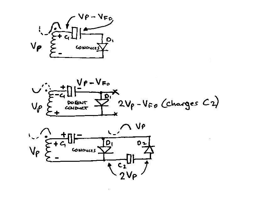 I'm not 100% convinced that the explanation given in the google book is that easy to understand, so here's my take on it, FWIW. I apologise for the awful sketches! On the first positive half cycle (sketch 1), D1 conducts, and C1 gets charged up to the peak voltage Vp (technically minus the diode drop, but we can effectively ignore that). On the second, negative half cycle (sketch 2) D1 doesn't conduct, but for half a cycle, you will see that the charge on C1 is effectively in series with the secondary, so that at the points x-x the voltage is now 2Vp. (Yes it's still minus that diode drop but that's only 0.7v or thereabouts.) You'll now notice that the voltage has doubled. In sketch 3, which we'll call the next half cycle, D1 conducts again, recharging C1. You will note that because of the behaviour of capacitors to a rate of change of voltage, the pulses effectively pass through C1 and C2, and the same behaviour takes place again in the next two stages, with a resultant 2Vp appearing across C4 as well. This gives you two capacitors in series with 2Vp across each of them, so if you take an output with the +ve terminal on the + side of C1 and the -ve terminal on the - side of C4, you have effectively quadrupled the output. The resultant output never makes it to the full Vp x 4, because any attempt to draw current will discharge the capacitors between half-cycles. And because the charge is based on the transfer of energy through capacitors, which have a very finite series resistance, the current available is pretty limited. Despite the claim, I don't think that all of the diodes are likely to see 2Vp as a peak inverse voltage across them - probably only the first one in a real-life situation, but I haven't checked that in detail. That may or may not be easier to understand. Hopefully if you read it in conjunction with the book, it may all make some sense! (Les posted his as I was preparing this one, but I'm pretty sure that even though the words are different, the explanations are essentially the same) Edited By Steve Garnett on 16/09/2011 23:50:37 |
| ian weeks | 17/09/2011 06:35:45 |
| 33 forum posts | Thanks again chaps, Am off for a hill walk in rosedale this morning with my wife ,have printed off your replies and when we run out of things to say will mull them over-thanks ian |
| Stub Mandrel | 18/09/2011 22:10:48 |
 4318 forum posts 291 photos 1 articles | Just a thought, lot's of folks worrying about using 7805s with high currents and supply voltages (30V+). The efficient alternative is a switch mode PSU. Now DON'T PANIC! There's a chip, the LM2595, 'simple switcher' that is not much more difficult to wire up than a 78series and it is vastly more efficient (about 90%, I think, when a 7805 on a 30V supply is only about 18% efficient). The LM2595 comes in 5, 12 1and variable versions. The downside is you need a 68uH coil that can take 1A and a shottky diode. Neil |
| Steve Garnett | 19/09/2011 00:19:44 |
| 837 forum posts 27 photos | Hmm.... Might be quite interesting running that in a box next to a MW radio! I'd already thought of using a small switcher, but decided that keeping it simple and linear might be better under the circumstances, although I must admit that I haven't mentioned this up till now. But you're right about the dissipation and efficiency, which is why I suggested using a 6v transformer to run the 7805, rather than the original 24v one, which is definitely OTT! |
| ian weeks | 20/09/2011 21:06:40 |
| 33 forum posts | Thanks for all the info ,the walk was fantastic and thanks to your explanations I think I understand the voltage multiplication circuit. Just back in from the shed ,having plucked up courage and attempted the LT side of the Stenning design -the soldering is atrocious ,2 out of 10 for neatness and as I didn't have the right value of resistor to hand made R6 18 R to give 1.36V. I am still recovering from the shock that it worked reading 1.345v on my meter. For you guys this must be kindergarten stuff but as I haven't done anything like this for over 40 years I am walking on air. Thanks again Ian |
| ian weeks | 29/09/2011 16:38:16 |
| 33 forum posts | Dear All, This should be titled'bench power supply ----almost' Last night had some spare time and as I can't get on with the radio supply till my order for 100v capacitors arrives decided to build the supply as detailed in MEW. Al went well LED lights /5v supply reads 5v but variable supply fries 180r resistor and when checked output is full 37v rectified dc I have checked the circuit wiring a dozen times and can't find I' ve done anything wrong [using chocolate box design as per magazine ] also if turn up Variable resistor makes expected 'warm' noises Any suggestions as to what I am doing wrong Ian |
| Steve Garnett | 29/09/2011 20:38:05 |
| 837 forum posts 27 photos | Well, if you take pin 2 of the LM317/338 to ground (-ve side of C1) and you still get the full output, that would indicate that you've got a dead short from input to output of the regulator - internally. Also, if the resistor is getting fried, it implies that pin 2 (which should only take a maximum of 100uA) is drawing current. Can't see any explanation other than this, I'm afraid - one fried regulator. Edited By Steve Garnett on 29/09/2011 20:38:48 |
| ian weeks | 01/10/2011 08:32:49 |
| 33 forum posts | Thanks steve, Will try what tou say but wont be till next weekend now as am off to snowdonia for the week Regards Ian |
| Stub Mandrel | 01/10/2011 20:13:17 |
4318 forum posts 291 photos 1 articles | I know this is a return to the beginning of thios thread, but this afternoon I found a scan of the 7805 datasheet on my PC. Hand typed, by the look of it. Apparently you DON'T need any capacitors with a 7805 as long as (a) the supply reservoir capacitor is big enough and (b) you aren't too picky about the transient response. So the 0.1-1.0uF cap on the output is only needed if you have a 'spiky' load. I think I'll keep using a 47uF on input and 0.1uF on output anyway. Neil |
| ian weeks | 19/10/2011 08:28:28 |
| 33 forum posts | Dear All , Once again thank you for your erudite postings in the recent past,they were a great help. Could I trouble you again for some information. last night at last found some spare time to 'play' in the shed . decided to build as much of the the ht circuit as I could [ really want to spend cold winters nights with the valve radio on the kitchen table!] Have done this apart from last 4 220 microfarad capacitors-finding hard to source 100v ones. While 'on a roll' Decided to re look at power supply and started on the variable side of the power supply as detailed in Mew and you were right Steve putting pin 2 to ground indicated dead short in lm 338. .Checked wiring and replaced 338 Same again 37v unvariable at out put. Spent rest of night poring over schematic [building using terminal block and my attempts at wiring. Cannot find discrepency . If you have time can you tell me if there is a problem with the published schematic? I,m beginning to become obessed with getting this to work!! On a lighter note while on the walking holiday in wales spotted an copy of electronics servicing vol2 for 50p in charity shop window- serendipity Thanks in anticipation Ian |
| Les Jones 1 | 24/10/2011 18:06:45 |
| 2292 forum posts 159 photos | Hi Ian, I have sent you a message about the problem. Look in "My messages" under your account. Les. |
Please login to post a reply.
Magazine Locator
Want the latest issue of Model Engineer or Model Engineers' Workshop? Use our magazine locator links to find your nearest stockist!
Sign up to our Newsletter
Sign up to our newsletter and get a free digital issue.
You can unsubscribe at anytime. View our privacy policy at www.mortons.co.uk/privacy
Latest Forum Posts
- hemingway ball turner
04/07/2025 14:40:26 - *Oct 2023: FORUM MIGRATION TIMELINE*
05/10/2023 07:57:11 - Making ER11 collet chuck
05/10/2023 07:56:24 - What did you do today? 2023
05/10/2023 07:25:01 - Orrery
05/10/2023 06:00:41 - Wera hand-tools
05/10/2023 05:47:07 - New member
05/10/2023 04:40:11 - Problems with external pot on at1 vfd
05/10/2023 00:06:32 - Drain plug
04/10/2023 23:36:17 - digi phase converter for 10 machines.....
04/10/2023 23:13:48 - More Latest Posts...
- View All Topics
Support Our Partners


Shopping Partners
Subscription Offer

Latest "For Sale" Ads
- Reeves** - Rebuilt Royal Scot by Martin Evans
by John Broughton
£300.00 - BRITANNIA 5" GAUGE James Perrier
by Jon Seabright 1
£2,500.00 - Drill Grinder - for restoration
by Nigel Graham 2
£0.00 - WARCO WM18 MILLING MACHINE
by Alex Chudley
£1,200.00 - MYFORD SUPER 7 LATHE
by Alex Chudley
£2,000.00 - More "For Sale" Ads...
Latest "Wanted" Ads
- D1-3 backplate
by Michael Horley
Price Not Specified - fixed steady for a Colchester bantam mark1 800
by George Jervis
Price Not Specified - lbsc pansy
by JACK SIDEBOTHAM
Price Not Specified - Pratt Burnerd multifit chuck key.
by Tim Riome
Price Not Specified - BANDSAW BLADE WELDER
by HUGH
Price Not Specified - More "Wanted" Ads...
Get In Touch!
Do you want to contact the Model Engineer and Model Engineers' Workshop team?
You can contact us by phone, mail or email about the magazines including becoming a contributor, submitting reader's letters or making queries about articles. You can also get in touch about this website, advertising or other general issues.
Click THIS LINK for full contact details.
For subscription issues please see THIS LINK.
Digital Back Issues


Donate

 Register
 Log-in
Model Engineer Magazine
- Percival Marshall
- M.E. History
- LittleLEC
- M.E. Clock

ME Workshop
- An Adcock
- & Shipley
- Horizontal
- Mill

Subscribe Now
- Great savings
- Delivered to your door

Pre-order your copy!
- Delivered to your doorstep!
- Free UK delivery!
All Forum Topics > Model Engineers' Workshop. > benchtop power supply