Forum sponsored by:

Stuart Twin Victoria (Princess Royal) Mill Engine
| JasonB | 14/11/2020 16:48:57 |
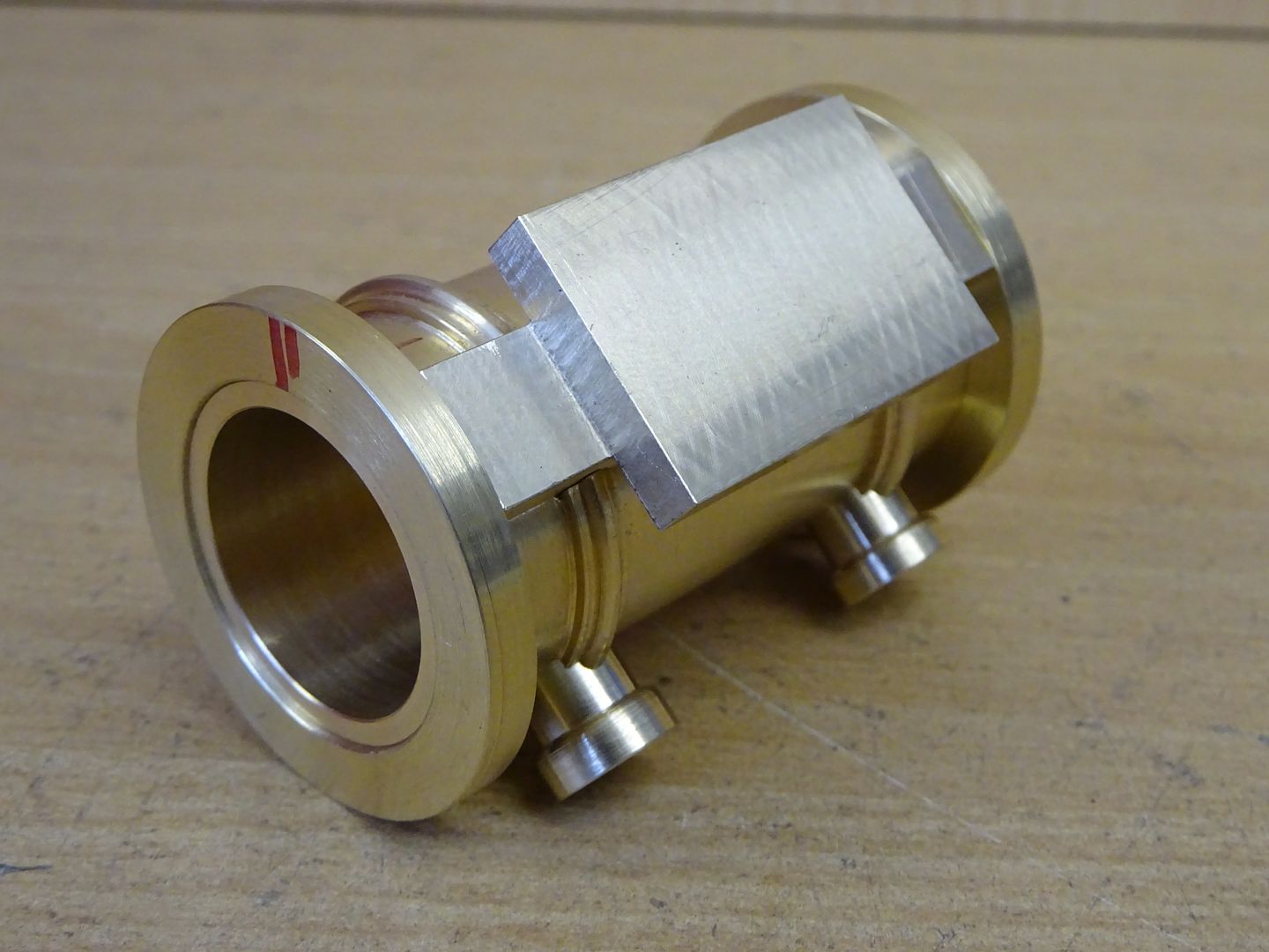
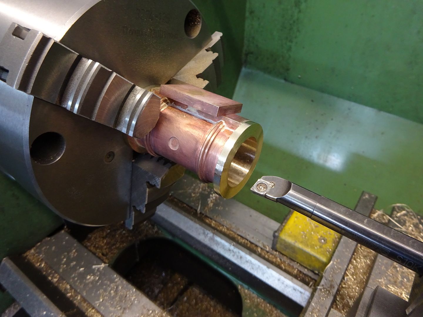
 25215 forum posts 3105 photos 1 articles | A lot will depend on how the individual machine bores, I would certainly have to take care to get it parallel and probably opt to do the last few passes with HSS as inserts can tend to get pushed off the surface more though **GT ones will reduce the tendency. Any slight taper can often be honed or lapped out. But as you say between ctrs should give a parallel bore. The longer the bore the more likely it is to taper as you have more of a standard poring bar hanging out the toolpost. Fabricated cylinders make it a bit easer to know that the end of the bore in the chuck is running true before you start but there are ways to make it easier with castings. The one I had started to draw up would have been with fabricate dcylinders
basically soldered up from brass and bronze
Bored after soldering and pickling
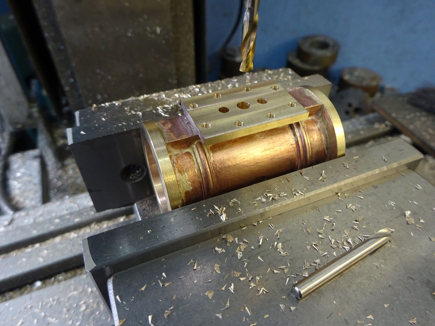
faces milled
|
| Dr_GMJN | 14/11/2020 17:17:50 |
 1602 forum posts | Nice work. How about with Ramon's PTFE rings? In practical terms is it going to matter about a very slight taper? I'll probably try the between centres approach, just for the sake of it. By the way - what is the usual way of aligning and fixing the cylinder if not on the cross slide t-slot bed? |
| Ramon Wilson | 14/11/2020 17:41:35 |
 1655 forum posts 617 photos | Packing it up from the bed is just fine - holding it to an angle plate or vertical slide allows infinite vertical adjustment but packing of the right height is okay. One thing to really take note of is not over tightening the clamps - not quite so important with cast iron as it is bronze but if you do distort it then the bore will be distorted once the clamps are released. This is one op where that simple slip of paper between the part and clamping surface pays dividends. If you make yourself an expanding mandrel as has already been suggested you can do both ends of the cylinder as normal facing operations absolutely square to the bore - no fly cutting required. Move that to the mill and you can do all the other ops from the centre line of that mandrel - either still in the lathe chuck if you have a dividing head or as already suggested too bolted to an angle plate or even a piece of steel held vertical in the milling vice. Doing the bore from the chuck is just as practical but you do run the risk of a taper - not much I grant you and yes you can lap it out but that's more tooling and another op. If you took a look at the link I posted you will have seen what I mean about a mandrel - once you make these and get used to working with them you will realise just how useful they are. It's much better to make your own. I have a set bought from Arc Euro - they've never been used because they are never quite right size wise. Any way you are In Jason's good hands so I'll bow out now - too many cooks etc - will end up getting you confused Good luck with your build - I may be joining you soon Regards - Ramon |
| Dr_GMJN | 14/11/2020 17:51:51 |
1602 forum posts | I appreciate your input as I do Jason's - I try to take the bits from both that I'm most comfortable with doing; I know all the advice is sound, any errors arising in the past have been through my own mis-interpretation. I had planned on using an expanding mandrel in order to find the finished bore axis in the mill - with the centre finder. I may have to reduce the end to a diameter that the finder tip can get to. I can then offset directly from the axis to setup for the fabricated feet edges, and in the other plane, for the feet and valve pad heights. |
| Ramon Wilson | 14/11/2020 18:21:22 |
1655 forum posts 617 photos | Take no offence Doc - but as it is confusing to have several inputs possibly in conflict at times I thought it might be for the best. I've always advocated 'listen to all' but 'make your own decision from what you've heard' - as you no doubt are aware that applies to plastic modelling as well as ME but too much information can become confusing especially for someone relatively new. I think I said before we all have differing techniques to achieve an end result - you have to decide which best suits your purpose, your equipment and knowledge. As said mandrels make for much easier approaches to many machining ops. I can thoroughly recommend you investigate their usefulness BTW the mandrel should be within the cylinder. Find the centreline of it on the mill before putting the cylinder on it Regards - Ramon
|
| Dr_GMJN | 04/12/2020 12:41:15 |
1602 forum posts | Quick update - I ordered the main castings yesterday. I've not started on the fabricated base yet becasue I've been distracted with machine fettling (and to be honest I lost interest in that half way through for various reasons), and it's very cold in the garage these days. I'll order the fasteners next month, then that'll be all the main components sorted out. |
| Dr_GMJN | 09/12/2020 16:55:23 |
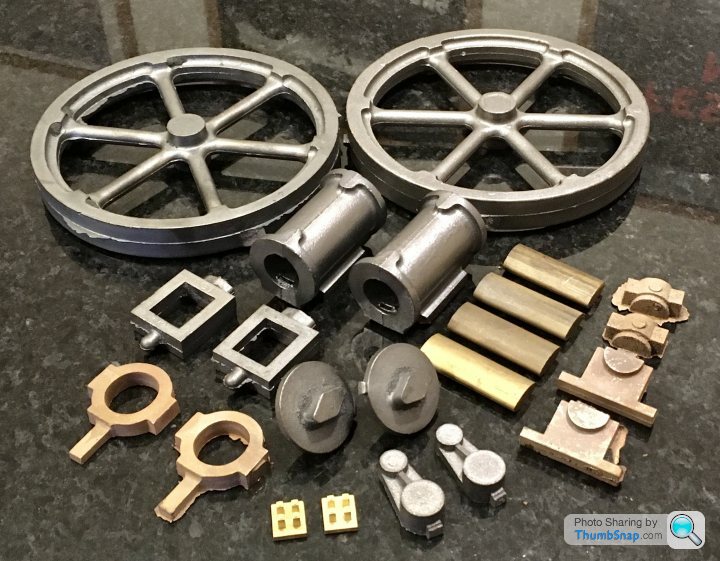
1602 forum posts | Well that’s about £300 of Stuart castings: |
| Dr_GMJN | 15/12/2020 21:35:51 |
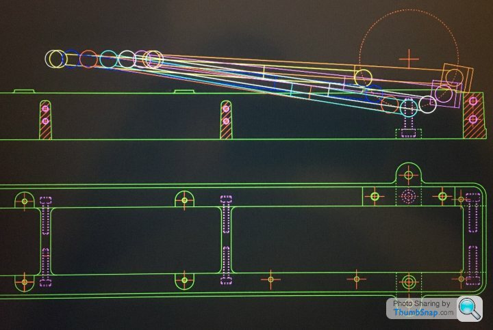
1602 forum posts | Been working a bit more on the soleplate CAD. Also spent some time verifying the geometry of the piston stroke/crosshead location/connecting rod etc: |
| Ramon Wilson | 15/12/2020 22:31:00 |
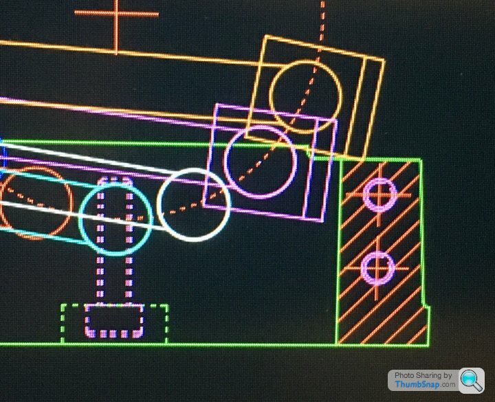
1655 forum posts 617 photos | Hi Doc G, The big end will need a groove milled or filed in the end brace unless, as you say, you extend the sides a small amount. Depends on how you feel about the aesthetics but to have a groove does follow full size practice as many bedplates have 'scallops' cast in for clearance around the rod movement. 'Perilously close' ? - a couple of thou gap is sufficient if there's no play in the moving parts - which is definitely the case on the Waller engine built - 'a miss is as good as a mile' springs to mind there Regards - Ramon
|
| JasonB | 16/12/2020 13:56:18 |
25215 forum posts 3105 photos 1 articles | Funny enough when sketching one out I did do a version with a rounded end to the base casting much like this engine but deleted the drawing a couple of weeks ago which would have given plenty of clearance. |
| Dr_GMJN | 16/12/2020 14:36:42 |
1602 forum posts | Thanks both. Ramon - I just looked again at your model and noticed the cut-out. I didn't see it previously, and I don't think you mentioned it before. The P.R. I saw online didn't have the cut-out, but it did have a different bearing cap. Jason - I'd prefer the non-rounded end TBH. First it's easier to make, and second I'm not sure I like the aesthetics (obviously personal preference). I'll have a play about and see what it looks like extended. By my reckoning if the end is moved over by c.7 mm, it gives a c. 3 mm clearance on the bearing cap, which probably isn't the end of the world.
|
| Ramon Wilson | 17/12/2020 10:22:19 |
1655 forum posts 617 photos | Dr G - this project is one you can take 'as far as you like'. The big end can be changed, the end relieved or the sides extended. The choice is yours and will be fine however you do it. A google search should soon find examples of stationary engine connecting rod 'big ends' - there are quite a few to choose from and most would be in keeping. I don't quite understand though when you refer to the 'bearing cap' ? Ramon
|
| JasonB | 17/12/2020 10:25:34 |
25215 forum posts 3105 photos 1 articles | "Bearing cap" = keep plate on the end of the conrod's split bearing but that would be with marine type big end and PR uses a strap? If it is a marine type big end then there will also be fixings that stick out further to contend with too. Edited By JasonB on 17/12/2020 10:28:07 |
| Ramon Wilson | 17/12/2020 11:01:34 |
1655 forum posts 617 photos | Thanks Jason - always thought of that as bearing 'keep' - for some reason I was thing Doc G was meaning the main bearing hence the confusion - easy for me these days! I don't think too many mill engines were fitted with marine type big ends were they?
|
| JasonB | 17/12/2020 11:19:21 |
25215 forum posts 3105 photos 1 articles | No, a strap with a wedge or a rectangular hole in the end of the rod for the bearing and wedge to close it up would be more typical. The strap can always be made as a dummy if the Doc does not want to do the detailed PR version. |
| Dr_GMJN | 18/12/2020 15:49:34 |
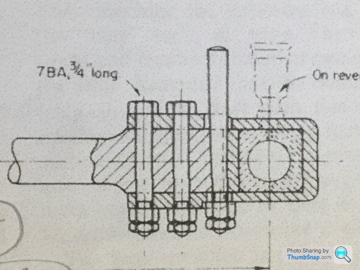
1602 forum posts | I was using car engine terms when I said bearing cap; I meant half the split block and retaining strap to the right of the drawing here: |
| Ramon Wilson | 18/12/2020 17:43:53 |
1655 forum posts 617 photos | Hi Doc, I did mine to print but as you have already seen you need to make allowance for it on the end bar if so. I would imagine it is true to prototype but if not quite in keeping with the period. You need to lubricate the crank pin even if non reversing. Either a simple type as shown but better (i.e. more realistic) if you do it through the end of the crankpin(s). If you want to make see through oilers an ideal material for the 'glass' are those crystal clear tubes you get as protectors on artists brushes. Ramon |
| Dr_GMJN | 18/12/2020 19:54:51 |
1602 forum posts | Posted by Ramon Wilson on 18/12/2020 17:43:53:
Hi Doc, I did mine to print but as you have already seen you need to make allowance for it on the end bar if so. I would imagine it is true to prototype but if not quite in keeping with the period. You need to lubricate the crank pin even if non reversing. Either a simple type as shown but better (i.e. more realistic) if you do it through the end of the crankpin(s). If you want to make see through oilers an ideal material for the 'glass' are those crystal clear tubes you get as protectors on artists brushes. Ramon Thanks Ramon, Yes - the one I'd seen that didn't have a cut-out had what I'd describe as a bearing cap, similar to a car engine. I think it's the marine type mentioned by Jason. The plans show a rotating crankpin oiler, but they imply they're only for show...but that they do in fact sort of work. All a bit confusing actually. I'll go with the plans, and if they work, fine, if not I'll add an additional oiler through the strap.
|
| Ramon Wilson | 18/12/2020 20:26:24 |
1655 forum posts 617 photos | Doc, I've just fitted a rotating crankpin oiler to the engine I'm building at present. I sourced some 1mm OD copper tube for other parts but used this as the drip feed to the crankpin pick up. At first I thought that the viscosity of the light oil usually used for lubing running engines was going to be too thick to pass but it was not long before the oiler had emptied - if you are up for it they do work then and do look more in keeping than a oiler on the big end - well worth doing. I did intend to fit this type of lubricator on my version - I think I even milled a pad to take a pedestal. I found the cups made recently but of course they never got fitted at the time. Ramon |
| Dr_GMJN | 19/12/2020 14:59:19 |
1602 forum posts | Ramon, do you have any drawings and/or photos of the oilers you mentioned you’d got working? Thanks. |

Please login to post a reply.
Magazine Locator
Want the latest issue of Model Engineer or Model Engineers' Workshop? Use our magazine locator links to find your nearest stockist!
Sign up to our Newsletter
Sign up to our newsletter and get a free digital issue.
You can unsubscribe at anytime. View our privacy policy at www.mortons.co.uk/privacy
Latest Forum Posts
- hemingway ball turner
04/07/2025 14:40:26 - *Oct 2023: FORUM MIGRATION TIMELINE*
05/10/2023 07:57:11 - Making ER11 collet chuck
05/10/2023 07:56:24 - What did you do today? 2023
05/10/2023 07:25:01 - Orrery
05/10/2023 06:00:41 - Wera hand-tools
05/10/2023 05:47:07 - New member
05/10/2023 04:40:11 - Problems with external pot on at1 vfd
05/10/2023 00:06:32 - Drain plug
04/10/2023 23:36:17 - digi phase converter for 10 machines.....
04/10/2023 23:13:48 - More Latest Posts...
- View All Topics
Support Our Partners


Shopping Partners
Subscription Offer

Latest "For Sale" Ads
- Reeves** - Rebuilt Royal Scot by Martin Evans
by John Broughton
£300.00 - BRITANNIA 5" GAUGE James Perrier
by Jon Seabright 1
£2,500.00 - Drill Grinder - for restoration
by Nigel Graham 2
£0.00 - WARCO WM18 MILLING MACHINE
by Alex Chudley
£1,200.00 - MYFORD SUPER 7 LATHE
by Alex Chudley
£2,000.00 - More "For Sale" Ads...
Latest "Wanted" Ads
- D1-3 backplate
by Michael Horley
Price Not Specified - fixed steady for a Colchester bantam mark1 800
by George Jervis
Price Not Specified - lbsc pansy
by JACK SIDEBOTHAM
Price Not Specified - Pratt Burnerd multifit chuck key.
by Tim Riome
Price Not Specified - BANDSAW BLADE WELDER
by HUGH
Price Not Specified - More "Wanted" Ads...
Get In Touch!
Do you want to contact the Model Engineer and Model Engineers' Workshop team?
You can contact us by phone, mail or email about the magazines including becoming a contributor, submitting reader's letters or making queries about articles. You can also get in touch about this website, advertising or other general issues.
Click THIS LINK for full contact details.
For subscription issues please see THIS LINK.
Digital Back Issues


Donate

 Register
 Log-in
Model Engineer Magazine
- Percival Marshall
- M.E. History
- LittleLEC
- M.E. Clock

ME Workshop
- An Adcock
- & Shipley
- Horizontal
- Mill

Subscribe Now
- Great savings
- Delivered to your door

Pre-order your copy!
- Delivered to your doorstep!
- Free UK delivery!
All Forum Topics > Work In Progress and completed items > Stuart Twin Victoria (Princess Royal) Mill Engine