Forum sponsored by:

Stuart Twin Victoria: Advice & General Questions
| Dr_GMJN | 22/10/2020 15:17:35 |
 1602 forum posts | All, thanks for the info - I will have a read through Andrew's linked thread. What I'm after ideally is a governor that works in terms of keeping a set speed under varying loads and inlet pressures (within certain limits obviously), but also be able to set different speeds easily. This might be a daft question, but are governors settable in terms of pre-set engine speed with a control lever or wheel? I want to be able to vary the speed of the engine rather than just "switch it on" and it run at a constant speed. I'm not too familiar with types of governors yet, but I guess there would be a way of switching between governed speed and controlling speed with a simple valve? The governor and valve system is going to be the most difficult aspect of this build I think, but it will be good to figure it out. |
| Dr_GMJN | 22/10/2020 15:30:42 |
1602 forum posts | Just a bit of info on costs. I've now got a breakdown of pretty much everything for the standard Twin Victoria, as included in the kit (not including governor items or postage). * Materials (Bright Drawn Mild Steel, Cast Iron, Bronze, Stainless and Silver Steel). Standard sections sometimes slightly larger than requested, and many lengths are longer than in the kit. Also includes the aluminium for the beds: £75.16 *Fasteners (studding is longer than required, and some fasteners are multiples of what I need): £42.80 *Castings (2x Flywheels, 2x Cranks, 2x Cylinders, 2x Valve Chests, 2x Front Cylinder Covers): £204.96 *Extrusions etc (2x Bearings, 2x Eccentric Straps, Oval Gland material): £52.92 *Plans: £16.68 Total Cost £392.52 Of course some materials are now not needed, and others need sourcing for the Princess Royal, but for the sake of a few pounds I think I'll order the raw materials and be done with it.
|
| Andrew Johnston | 22/10/2020 15:48:01 |
 7061 forum posts 719 photos | Posted by Dr_GMJN on 22/10/2020 15:17:35:
What I'm after ideally is a governor that works in terms of keeping a set speed under varying loads and inlet pressures (within certain limits obviously), but also be able to set different speeds easily. Dream on! The centrifugal type governors, with a fixed relationship between ball position and valve opening, are not intended to work with varying control speeds. They simply attempt to control a single speed (set during design) as the load varies. It is inevitable that a change in load causes a change of speed. The objective is to minimise the change of speed with change of load. In terms of the s-plane that means the poles need to be as close to the imaginary (y) axis as possible while still remaining in the left hand side of the plane. Pickering governors (as on my traction engine) have a "speed" adjuster worm and worm wheel. But this is a misnomer. An early Pickering patent makes it clear that this control is not intended to adjust the governed speed. Later Pickering patents came up with varying ways to adjust the governed speed by changing the relationship between ball position and valve position while not affecting the operation of the governor. In summary centrifugal governors are some way short of being ideal. Where speed control is vital, as on mill engines, governors were developed that controlled the valve events (varying cutoff) rather than a simple throttle valve. I'm not convinced that simple governors are feedback systems. I think they're open loop and simply move along a speed/load line as the load varies. There is no attempt to correct for the speed error that arises from any change of load. Recently there was an intense debate on TractionTalk concerning governors. It was stated that governors work in the z-plane, ie, sampled data transforms rather than Laplace transforms. Given that the proponent of the idea got confused about sampling frequencies and Nyquist rates I wasn't convinced! However, I would agree that the stability of the system relies to some extent on the response of the whole engine, not just on the governor and valve. Andrew |
| JasonB | 22/10/2020 16:00:24 |
 25215 forum posts 3105 photos 1 articles | At best all you could do is have some way to override the governor when you want to play with the engine speed which should no be too hard to arrange by either disengaging the linkage or locking the valve in the open position then you can adjust speed as you did with your 10V. Governors are not meant to be adjusted on the fly, either pretension on the springs, position of a counter weight or some other method would be adjusted when they are set up for the job in hand and then not touched again. |
| roy entwistle | 22/10/2020 16:04:21 |
| 1716 forum posts | I always understood that governors on steam engines were to stop the engine running away if the load was suddenly lost, ie. drive belt broken or slipped off pulley. There was a device in the rope race of a mill to detect broken drive ropes. Edited By roy entwistle on 22/10/2020 16:06:25 Edited By roy entwistle on 22/10/2020 16:06:55 |
| Dr_GMJN | 22/10/2020 16:10:02 |
1602 forum posts | Posted by Andrew Johnston on 22/10/2020 15:48:01:
Posted by Dr_GMJN on 22/10/2020 15:17:35:
What I'm after ideally is a governor that works in terms of keeping a set speed under varying loads and inlet pressures (within certain limits obviously), but also be able to set different speeds easily. Dream on! The centrifugal type governors, with a fixed relationship between ball position and valve opening, are not intended to work with varying control speeds. They simply attempt to control a single speed (set during design) as the load varies. It is inevitable that a change in load causes a change of speed. The objective is to minimise the change of speed with change of load. In terms of the s-plane that means the poles need to be as close to the imaginary (y) axis as possible while still remaining in the left hand side of the plane. Pickering governors (as on my traction engine) have a "speed" adjuster worm and worm wheel. But this is a misnomer. An early Pickering patent makes it clear that this control is not intended to adjust the governed speed. Later Pickering patents came up with varying ways to adjust the governed speed by changing the relationship between ball position and valve position while not affecting the operation of the governor. In summary centrifugal governors are some way short of being ideal. Where speed control is vital, as on mill engines, governors were developed that controlled the valve events (varying cutoff) rather than a simple throttle valve. I'm not convinced that simple governors are feedback systems. I think they're open loop and simply move along a speed/load line as the load varies. There is no attempt to correct for the speed error that arises from any change of load. Recently there was an intense debate on TractionTalk concerning governors. It was stated that governors work in the z-plane, ie, sampled data transforms rather than Laplace transforms. Given that the proponent of the idea got confused about sampling frequencies and Nyquist rates I wasn't convinced! However, I would agree that the stability of the system relies to some extent on the response of the whole engine, not just on the governor and valve. Andrew So you couldn't simply change the ratio of the governor drive, to change the speed of the engine? |
| Dr_GMJN | 22/10/2020 16:12:46 |
1602 forum posts | Posted by JasonB on 22/10/2020 16:00:24:
At best all you could do is have some way to override the governor when you want to play with the engine speed which should no be too hard to arrange by either disengaging the linkage or locking the valve in the open position then you can adjust speed as you did with your 10V. Governors are not meant to be adjusted on the fly, either pretension on the springs, position of a counter weight or some other method would be adjusted when they are set up for the job in hand and then not touched again. Yes, that's what I meant by switching between governed speed and using a simple valve. I'd assumed that on a traction engine they were pre-settable, but then again I'm on a steep learning curve here... |
| Andrew Johnston | 22/10/2020 16:23:47 |
7061 forum posts 719 photos | Posted by Dr_GMJN on 22/10/2020 16:10:02:
So you couldn't simply change the ratio of the governor drive, to change the speed of the engine? Well you could, but I've never heard of it being done and I can't immediately see why one would want to. Enginemen of old would have been interested in getting the job done, taking the money and moving on. Not faffing about changing pulleys and belts. Andrew |
| Ramon Wilson | 22/10/2020 16:26:47 |
 1655 forum posts 617 photos | Doc G - you will certainly not be the first to want to have a properly 'working' governor and many have tried before but like most things as matters are scaled down the physical effects don't scale with them. As Andrew aludes - it's a bit of a holy grail. But he's right, a governor is just that - a device to govern the set speed the engine is designed to run at. Load comes on governor gives more steam - Load comes off vice versa. They aren't designed to work through varying speeds and they don't work as well on air. Only this morning I have my latest build running - very happy with it just on one of two cylinders. It will run through a range of speeds depending on the stop valve setting. Couple up the governor and it's affect is instant - hunting back and forth as speed increases and decreases. Though the spring is to design first thoughts are that it obviously needs to be much stronger to over come this problem. If the governor is to work effectively the speed will be set by it and not by the stop/inlet valve. The Lang Bridge Double Diagonal engine built has no governor. When I made it I phoned the supplier to ask why. None on the original came the answer - it was designed to drive a calico printing press which required varying speeds depending on (the printed) design. The full size engine was controlled by the stop valve. Personal view is if the governor will give a bit more when drag is applied to the flywheel it's working but if it's having a detrimental effect on performance then it's cosmetic only. Ramon
|
| Dr_GMJN | 22/10/2020 16:40:14 |
1602 forum posts | Posted by Andrew Johnston on 22/10/2020 16:23:47:
Posted by Dr_GMJN on 22/10/2020 16:10:02:
So you couldn't simply change the ratio of the governor drive, to change the speed of the engine? Well you could, but I've never heard of it being done and I can't immediately see why one would want to. Enginemen of old would have been interested in getting the job done, taking the money and moving on. Not faffing about changing pulleys and belts. Andrew
It was just an idea, to achieve what I'd asked for. I wasn't suggesting that's how it was or should have been done, full size. I just wanted to know if there was some way to vary the speed of a governor-equipped model engine; slow - medium - high, and to show how if you load the flywheel (within each setting), the governor attempts to correct the speed. On a model with a spring band driven governor it would be a simple case of slipping the band from one part of a stepped pulley to another. If it didn't work out, fine, swap the pulley to a single diameter and you've lost nothing.
|
| Dr_GMJN | 22/10/2020 17:35:52 |
1602 forum posts | Posted by Ramon Wilson on 22/10/2020 16:26:47:
Doc G - you will certainly not be the first to want to have a properly 'working' governor and many have tried before but like most things as matters are scaled down the physical effects don't scale with them. As Andrew aludes - it's a bit of a holy grail. But he's right, a governor is just that - a device to govern the set speed the engine is designed to run at. Load comes on governor gives more steam - Load comes off vice versa. They aren't designed to work through varying speeds and they don't work as well on air. Only this morning I have my latest build running - very happy with it just on one of two cylinders. It will run through a range of speeds depending on the stop valve setting. Couple up the governor and it's affect is instant - hunting back and forth as speed increases and decreases. Though the spring is to design first thoughts are that it obviously needs to be much stronger to over come this problem. If the governor is to work effectively the speed will be set by it and not by the stop/inlet valve. The Lang Bridge Double Diagonal engine built has no governor. When I made it I phoned the supplier to ask why. None on the original came the answer - it was designed to drive a calico printing press which required varying speeds depending on (the printed) design. The full size engine was controlled by the stop valve. Personal view is if the governor will give a bit more when drag is applied to the flywheel it's working but if it's having a detrimental effect on performance then it's cosmetic only. Ramon
Thanks Ramon. a surprisingly difficult decision - working governor, or cosmetic. I know that I'll at least have to try to get one working I suppose. Do you by any chance have plans that incorporate an rc engine barrel type valve? At first glance, the Princess Royal articles describe a butterfly valve. TBH I don't fancy my chances of being successful with that, or at least I fear for my mental health if I resolved to get it working... Regarding the "hunting" issue - isn't this more of a damping problem than a spring rate problem? |
| Andrew Johnston | 22/10/2020 21:52:33 |
7061 forum posts 719 photos | Posted by Ramon Wilson on 22/10/2020 16:26:47:
Couple up the governor and it's affect is instant - hunting back and forth as speed increases and decreases.
Hunting can occur as a result of the governor being too sensitive, but it can also be the result of unwanted friction in the valve operating mechanism effectively creating a deadband. Andrew |
| Ramon Wilson | 22/10/2020 22:39:38 |
1655 forum posts 617 photos | Hi Andrew, I think its more likely the former than the latter. It's early days as yet as to what the cause actually is. The movement of all the linkage is very free but positive with no slack. It's a Hargreaves type and the weights do have a bit of play before they impinge on the spring but as they are not in contact at that point I can't see that as being a reason. If the engine speed is increased considerably then effect decreases in proportion which reinforces my earlier point of a governor 'setting'the engine speed and not the stop valve. At this stage however I'm not too bothered as to the cause as there is still the second LP cylinder to couple up to the first and get the valve gear in tune with the HP Dr G - I don't have any plans or even drawings of the 'throttles' I fitted. I just drew them up at the appropiate time to fit inside the valve body as designed - it is no more than a rotary motion - getting the areas right in conjunction with the motion available and the desired speed is another matter. Hence my ready acceptance to see the governor as more cosmetic than functional. Don't let me put you off by that - if solving such problems is the type of challenge you enjoy then by all means try - just don't be too disappointed in the result if it doesn't quite turn out to what you hope. Regards - Ramon
|
| Dr_GMJN | 22/10/2020 22:42:50 |
1602 forum posts | So I’ve read all the Princess a Royal articles now. I think I can at least give it a go as per TC’s description and plans. There are however a few things that I know will be difficult for me. Mainly these are around making tools. Apart from the eccentric groove tool on the 10V (which was very easy to make), I’ve no experience of making HSS tooling. So the keyway tool and holder, the flywheel rope groove tools and the internal groove tools for the eccentric straps are all a mystery. Also, are carbide straight-through boring bars available? Any advice - as ever - is appreciated. By the way, I smiled when I read the final part of the governor articles just now: CT mentions that the equilibrium engine speed can be adjusted by changing the governor drive pulley diameters, or by hanging small weights on the actuating levers, ie what I wanted the option of doing. Whether I’ll be able to replicate the success of Ramon’s and CT’s governed engines remains to be seen. |
| Ramon Wilson | 22/10/2020 23:01:55 |
1655 forum posts 617 photos | I'm afraid I won't be much help where carbide tooling is concerned but I can where HSS is. A bit early to go into specifics as yet but have used nothing else and home made carbon steel cutters for many years. Remember - Experience only comes with practice. Making tooling is part of that. Once you've made your 'through hole' boring bar you won't need to again and so on. Help is at hand on anything like that but it's probably best to ask when you require it. Happy to help at any time as I'm sure others will be That's it for today - the duvee beckons! |
| JasonB | 23/10/2020 07:17:07 |
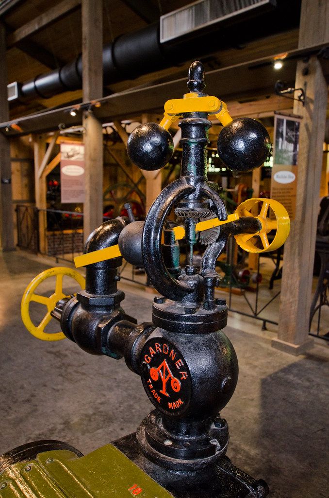
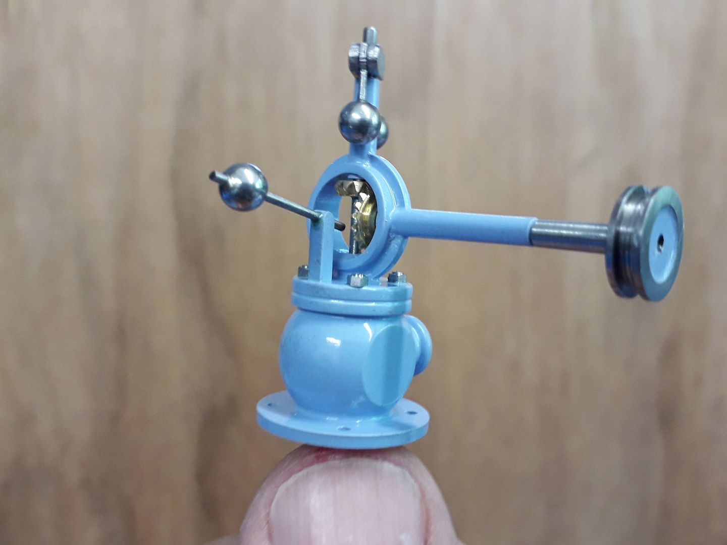
25215 forum posts 3105 photos 1 articles | I also mentioned counter weights earlier as well as adjusting spring tension as ways to adjust the governor which alters the load the centrifugal force from the weights needs to overcome, pulley changes would just be a way of altering the centrifugal force against a fixed load. As you say you want gear/shaft drive the pully option is not going to work here anyway. The problem still comes down to scale, I recently modelled an engine that had a Gardner style governor, these use a weight on an arm to set them.
I decided a show governor was the best I could manage as the weight was only 3/16" diameter, arm 1mm dia and had I wanted it to work that thin rod going down to actuate the internals would have been about 0.3mm and the screw that locks the weight on the shaft M0.4
|
| Ramon Wilson | 23/10/2020 08:49:51 |
1655 forum posts 617 photos | Very nice work as usual Jason It supports my view on scaling - those balls on the full size would have a fair amount of mass but 3/16 balls would not quite be in the same league eh? First line of approach will be a stronger spring but that's a day or three off yet. |
| Dr_GMJN | 23/10/2020 08:50:07 |
1602 forum posts | That’s a beautiful bit of work Jason. Yes I didn’t want a band drive because I get the impression from my old Mamod and Wilesco engines that they have a lot of spring, and might just make a marginal governor unworkable (and mine will probably be marginal at best tbh). I’ve not decided yet. Thanks Ramon, I guess I’ll ask again as and when about tooling. I’ve got to now amend my materials list in line with the P.R., and I’ll place an order next week for what it’s worth. Looks like there was an error in the list, So I can probably knock £20 worth of bronze off the price. I’ve then got some machine work to do (ML7 wide bed conversion, settable dials, thrust bearings and a threading handle, and sort out the dodgy head strut on the mill). All being well Ill make a start on the P.R. early next year.
Cheers all.
|
| Andrew Johnston | 23/10/2020 09:03:12 |
7061 forum posts 719 photos | Posted by Ramon Wilson on 23/10/2020 08:49:51:
It supports my view on scaling - those balls on the full size would have a fair amount of mass but 3/16 balls would not quite be in the same league eh? Mass scales as a cube law. So on my 4" scale engine I'm down by a factor of 27 on mass. It's the main reason why scale governors that rely on mass for sensing are difficult to get working. I've done my best to ameliorate the problem by making the balls slightly oversize and making them from tungsten alloy. Even the screw holding the ball halves together is made from a tungsten TIG electrode. Platinum was ruled out on cost grounds. Andrew |
| Ramon Wilson | 23/10/2020 09:32:21 |
1655 forum posts 617 photos | Dr G I was never happy with the appearance of the belt I used on my Twin Vic - it was made from o ring material joined with super glue. It was easy enough to make and it worked ok - for a time - but would often break during running at a show. Incidentally that did show that the engine was governed to a degree as it would instantly race away. I was given a drive belt from a tape deck that I used on the Waller engine - flat in section, about 4mm wide and less than a mill thick it hasproved ideal - it's still the original one. I used a similar but smaller version on the McOnie and again a wider and slightly thicker version on the latest engine. Black in colour theres a degree of stretch but not enough to be 'elastic' and importantly they appear unaffected by the oil that's always around. Lots to choose from on Ebay. If you intend to go down the HSS route you do need a decent off hand grinder but you don't need to buy in lots of HSS blanks. If you use throw away cutters on your mill then the shanks of these make superb lathe tools held in mild steel holders - after all its only the very tip of the tool that is in use - as long as you have that right whats behind it doesn't matter. Much easier that grinding away 5/16 or 3/8 square blanks - they are easily held in a round holder by a grub screw for grinding and cheap - free in fact if the cutter has had a useful life. If you don't have any - I have plenty of spare I did consider using a heavy metal Andrew as the weights are quite small but in the end decided it wasn't really worth the effort or expense - this will work out fine in the end I'm sure even if it is only just going 'round' Regards - Ramon
Edited By Ramon Wilson on 23/10/2020 09:32:47 Edited By Ramon Wilson on 23/10/2020 09:35:36 |
Please login to post a reply.
Magazine Locator
Want the latest issue of Model Engineer or Model Engineers' Workshop? Use our magazine locator links to find your nearest stockist!
Sign up to our Newsletter
Sign up to our newsletter and get a free digital issue.
You can unsubscribe at anytime. View our privacy policy at www.mortons.co.uk/privacy
Latest Forum Posts
- hemingway ball turner
04/07/2025 14:40:26 - *Oct 2023: FORUM MIGRATION TIMELINE*
05/10/2023 07:57:11 - Making ER11 collet chuck
05/10/2023 07:56:24 - What did you do today? 2023
05/10/2023 07:25:01 - Orrery
05/10/2023 06:00:41 - Wera hand-tools
05/10/2023 05:47:07 - New member
05/10/2023 04:40:11 - Problems with external pot on at1 vfd
05/10/2023 00:06:32 - Drain plug
04/10/2023 23:36:17 - digi phase converter for 10 machines.....
04/10/2023 23:13:48 - More Latest Posts...
- View All Topics
Support Our Partners


Shopping Partners
Subscription Offer

Latest "For Sale" Ads
- Reeves** - Rebuilt Royal Scot by Martin Evans
by John Broughton
£300.00 - BRITANNIA 5" GAUGE James Perrier
by Jon Seabright 1
£2,500.00 - Drill Grinder - for restoration
by Nigel Graham 2
£0.00 - WARCO WM18 MILLING MACHINE
by Alex Chudley
£1,200.00 - MYFORD SUPER 7 LATHE
by Alex Chudley
£2,000.00 - More "For Sale" Ads...
Latest "Wanted" Ads
- D1-3 backplate
by Michael Horley
Price Not Specified - fixed steady for a Colchester bantam mark1 800
by George Jervis
Price Not Specified - lbsc pansy
by JACK SIDEBOTHAM
Price Not Specified - Pratt Burnerd multifit chuck key.
by Tim Riome
Price Not Specified - BANDSAW BLADE WELDER
by HUGH
Price Not Specified - More "Wanted" Ads...
Get In Touch!
Do you want to contact the Model Engineer and Model Engineers' Workshop team?
You can contact us by phone, mail or email about the magazines including becoming a contributor, submitting reader's letters or making queries about articles. You can also get in touch about this website, advertising or other general issues.
Click THIS LINK for full contact details.
For subscription issues please see THIS LINK.
Digital Back Issues


Donate

 Register
 Log-in
Model Engineer Magazine
- Percival Marshall
- M.E. History
- LittleLEC
- M.E. Clock

ME Workshop
- An Adcock
- & Shipley
- Horizontal
- Mill

Subscribe Now
- Great savings
- Delivered to your door

Pre-order your copy!
- Delivered to your doorstep!
- Free UK delivery!
All Forum Topics > General Questions > Stuart Twin Victoria: Advice & General Questions