Forum sponsored by:

Myford Super 7 screw cutting gears (metric)
| John Stevenson | 20/03/2017 02:18:54 |
 5068 forum posts 3 photos | Simon, Do you have a set of 20DP gear cutters or just a few? I reckon we can get the 29T to run well instead of the 30T but need to do a bit of calculation.
It won't be until tomorrow night as only just walked in after a 160 mile drive and a bit wasted. |
| Brian Wood | 20/03/2017 08:41:33 |
| 2742 forum posts 39 photos | This is now getting very interesting. I have to be out much of the day but will follow developments with keen interest later. Just briefly though, thank you Dennis for the added information, pictures would be good and I'll PM you later |
| Simon Williams 3 | 20/03/2017 09:47:33 |
| 728 forum posts 90 photos | Morning John, Brian JS - Complete set of 20DP 14 1/2 deg cutters in stock, they're only Garvin ones but all there and almost new. It's the only complete set I do have. Also confirm I've got a 29 circle on one of my division plates. If I cut 29 div's on a blank of OD size for 30 T (1.600 ins) how do I modify the tooth depth calculation (and choose a different cutter???) to be sure the otherwise oversize 29 teeth don't jam in the 30 T they mate with. Mind you, this 30 T is home-made (aluminium) as you may have spotted from the photo's, so it's a pound to a pinch of snuff the teeth were cut slightly over deep. Do I cut 29 teeth to the depth they would be if the blank were the correct size = 1.55 OD less 0.108 depth of cut each side = 1.334 which is the PCD of the root of the 29 tooth gear cut normally?. That's 0.133 depth of cut each side from the 1.6 dia blank. Brian - I was going to tackle (am just starting) the calculations to see how near the "correct" pitch this gives for the relevant choices. (Is it worth the bother of making the gear?) It's a wet and rainy day, so it's that or the hoovering... Best rgds Simon |
| steamdave | 20/03/2017 10:49:47 |
| 526 forum posts 45 photos | Posted by John Stevenson on 18/03/2017 16:25:08:
At the risk of stealing Brian's thunder, may I pass a link on to his new book. Gearing of lathes for Screwcutting by Brian Wood, published by Crowood Press. I recently picked a copy up from ARC and it makes for very interesting reading and a lot of work has gone into this publication.
However from Crowoods page you can actually see part of this book and the modification that Brian talks about. And the typo on the contents page. Should it not be a SouthBEND lathe rather than a SouthBOUND lathe? Dave |
| John Stevenson | 20/03/2017 15:25:13 |
5068 forum posts 3 photos | Posted by Simon Williams 3 on 20/03/2017 09:47:33:
Morning John, Brian JS - Complete set of 20DP 14 1/2 deg cutters in stock, they're only Garvin ones but all there and almost new. It's the only complete set I do have. Also confirm I've got a 29 circle on one of my division plates. If I cut 29 div's on a blank of OD size for 30 T (1.600 ins) how do I modify the tooth depth calculation (and choose a different cutter???) to be sure the otherwise oversize 29 teeth don't jam in the 30 T they mate with. Mind you, this 30 T is home-made (aluminium) as you may have spotted from the photo's, so it's a pound to a pinch of snuff the teeth were cut slightly over deep. Do I cut 29 teeth to the depth they would be if the blank were the correct size = 1.55 OD less 0.108 depth of cut each side = 1.334 which is the PCD of the root of the 29 tooth gear cut normally?. That's 0.133 depth of cut each side from the 1.6 dia blank. Brian - I was going to tackle (am just starting) the calculations to see how near the "correct" pitch this gives for the relevant choices. (Is it worth the bother of making the gear?) It's a wet and rainy day, so it's that or the hoovering... Best rgds Simon Simon, Use a No 5 cutter instead of a No 6 and cut to 0.112" deep The gear blank needs to be the same size as the 30T one but you cut 29 on it.
I'll explain later tonight when I have a minute. |
| Simon Williams 3 | 20/03/2017 16:39:34 |
| 728 forum posts 90 photos | John - Thank you for the update, I'm very interested to understand the process behind those figures. I think you can guess what I'm planning to do tomorrow!
Brian - Here's my attempt at the arithmetic. For my old style gearbox, if I replace the 12T gear with a 17 T and select 18TPI, I get 12/17 x 18 TPI = 12.706. Pitch of 12.706 TPI = 1.999 mm. For 2.5 pitch, I replace the 30/12 pair with a 29/16 combo gear, select 14TPI as per the table above. Now my lathe cuts 12/16 x 29/30 x14TPI = 10.15 TPI, or 2.5025 pitch. Pitch error is +0.1% (contrast error of - 0.2% with 33T gear on new gearbox.) For 3.5 pitch replace 30/12 pair with 29/16 and select 10TPI. Lathe now cuts 12/16 x 29/30 x 10 TPI = 7.250TPI, 3.5024 pitch. Error is + 0.1%, error on "new" lathe is - 0.2% So I think we're onto something here. Obviously multiples and sub multiples of these pitches come out with the same error, so that's OK. Haven't looked at sub 1.0 pitches, probably never going to happen. Would appreciate your confirmation! Best rgds Simon |
| Brian Wood | 20/03/2017 16:39:42 |
| 2742 forum posts 39 photos | Hello Steamdave, Too late now to do anything about it of course, I do hope though it won't put you off reading the book and getting something useful out of it. |
| Brian Wood | 20/03/2017 17:21:53 |
| 2742 forum posts 39 photos | Hello Simon,
|
| Simon Williams 3 | 20/03/2017 19:38:05 |
| 728 forum posts 90 photos | Brian - Not sure we're on the same page here! 24TPI selected driven by 17 T gear produces 1.5 mm pitch. Equally 10 TPI selected gives pitch of 3.6 mm. If nothing else this is pro-rata from established start point where 18 TPI selected produces a thread of 2 mm pitch as per the table published on page 1 of this thread. Just to be sure I've gone out to the shed and tried both, can confirm as above. Rgds Simon |
| Allan B | 20/03/2017 20:11:55 |
 133 forum posts 23 photos | I know there is a lot of maths going on here in the background, would one of you very nice knowledgeable gentlemen mind sharing some of your workings out so I can try and get my head round it? |
| John Stevenson | 20/03/2017 20:44:28 |
5068 forum posts 3 photos | No Edited By John Stevenson on 20/03/2017 20:45:49 |
| John Stevenson | 20/03/2017 21:12:51 |
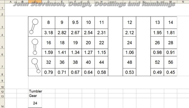
5068 forum posts 3 photos | Allan, Just joking. In my case the maths were done years ago and TBH I'd probably struggle to sort out what I did nowadays. Because these questions always came up I wrote a spreadsheet and upon this I superimposed a drawing of the Myford gearbox legend. This is the standard plate with the 24 driver.
Top row of number per row is the standard imperial tpi from 8 to 56. The lower row of numbers which make no sense are the pitch in mm.
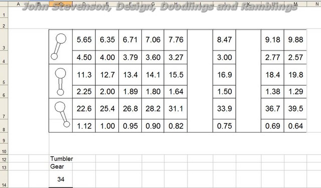
However if we swap the 24 for any other number, things change dramatically.
Here we have changed the 24 to one of the magic number, in this case 34 and the top boxes are now gibberish but the lower boxes have the number we need for metric threads.
So the maths you need are embedded and hidden under that image of the legend plate. This spreadsheet was written about 1998 or so hence my fuzzy memory of just what it does. |
| Allan B | 20/03/2017 22:21:51 |
133 forum posts 23 photos | That makes sense John, I can work out the gear ratios, the bit I was interested in was converting the gear ratio, even a compound gear ratio into the TPI of the thread, I can do it with motorcycle gearboxes, but that is converting horse power and talk, but not into actual movements in a linear motion |
| Simon Williams 3 | 20/03/2017 22:28:38 |
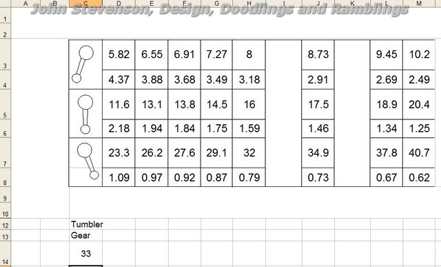
| 728 forum posts 90 photos | Evening all! Well, bless my soul, that's a mighty pretty summary of where we've got to! Thank you John. Do you have a spread sheet printout with the tumbler gear set to 33T? Allan - request for explanation noted, really John's spreadsheet says it all, provided we don't worry too much about what's hiding inside the gearbox. It's only really the relation between the spindle and the carriage travel we're concerned with, and that's what the label on to top of the Q/C gearbox details. What John has done (bodger that he is) is to alter the input gear ratio driving the gearbox, which alters the amount that the carriage moves each revolution of the spindle. It happens that the alteration chosen magically makes the carriage movement fit most of the useful numbers of the metric series of threads, hence being now able to cut metric threads - or at least a damn fine approximation thereto - with an 8 TPI leadscrew. It's just a confusion that the imperial threads are traditionally measured in Threads Per Inch, and metric threads are expressed in the pitch between successive crests, measured in millimetres. They are actually the same thing expressed in two ways. I've gone and confused the otherwise confusing logic of this by finding that the gearbox fitted to my lathe happens to run at half the speed of the one John's calculations were designed for, so all this stuff about 17 tooth gears is me trying to bodge my way round this. I suggest you ignore that for the time being. The arithmetic is actually fairly simple - or at least I think it is though I'm waiting on Brian to tell me I've misunderstood something. The usual gearbox is fed from a 24 tooth gear. How the motion gets to the leadscrew doesn't matter, but the lever positions tell us the overall result, expressed in TPI. John's spreadsheet replicates this, AND adds the information of the thread pitch in mm. Remember it's the same information, just expressed in a different way. What we've then done - not my idea, I take no credit for this, is to change the gear driving the gearbox, so that for the same speed of the headstock we have changed the speed of the leadscrew, hence the carriage travels at a different speed, and the TPI numbers (and thus pitches) alter. There's nothing magic about this except for the canny choice of the new driving gear, the gearbox itself hasn't changed and so the output variable - the speed at which the carriage travels along the bed - varies in strict ratio of the new driving gear to the old driving gear. The original Myford set-up drove the gearbox with a 24T gear. We've decided that's not good enough, and now decided to drive it with a 34 tooth gear. So all the thread pitches (gearbox outputs) increase by 34/24, which is what John's spread sheets show, and the TPI's of course reduce by the same proportion. The clever bit is that someone realised that by choosing 34 as the new number many of the new pitches happen to fall neatly into the numbers you would want to cut metric threads. Eh voila! Metric threads on an imperial lathe. This cunning plan was developed further by realising than some other useful (metric) pitches fell into place if said input gear was now altered to be 33 teeth. So now for an apology, because I've come into this late, and presumed to write this up, but it's not my idea and I've got a sneaky feeling that the clever chap who did think of it is somewhere in the mix of this thread. Gent's I apologise unreservedly for my arrogance in taking this upon myself, I only hope I've got it right! Hope this helps, best rgds to all Simon
|
| John Stevenson | 20/03/2017 22:50:37 |
5068 forum posts 3 photos | 33T gear fitted.
|
| Roderick Jenkins | 20/03/2017 23:21:14 |
 2376 forum posts 800 photos | Posted by Simon Williams 3 on 20/03/2017 22:28:38:
So now for an apology, because I've come into this late, and presumed to write this up, but it's not my idea and I've got a sneaky feeling that the clever chap who did think of it is somewhere in the mix of this thread. Gent's I apologise unreservedly for my arrogance in taking this upon myself, I only hope I've got it right! The earliest reference to this method I can find is from The Rev. David Hoskin in Vol 171, issue 3955 of Model Engineer. JS has done much to publicise the technique and make the gears available and I, for one, am very grateful to him. Rod |
| John Stevenson | 20/03/2017 23:30:21 |
5068 forum posts 3 photos | Post to explain how corrected gears can be cut using standard cutters to a reasonable accuracy** Could be long and may need to be in two parts because of the length of it, so best go get a coffee and throw the cat out.
Bit of background first and some of this may be simple but as I don't know who's reading this I need to explain the whole. Making corrected gears is something that is done in industry all the while. Strip and measure any modern automobile gearbox and I'll bet none of the gears are standard, all modified for strength, quietness etc. In production work it's easy to modify corrected gears as any manufacturing method that uses the GENERATING method like hobbing, shaping etc will form the corrected involute automatically.
Unfortunately the home shop method uses FORMING which is limited to the shape of the forming cutter.
As every gear as it increases in tooth number has a different shape then we need a different cutter for each shape, rather a tall order to have say 100 cutters and then you need a hundred in every pitch or DP ] you want to use.
So very early on Brown and Sharpe decided to 'band' these as the differences are very slight. The bands were numbered 1 to 8 so only eight cutters were needed per set. Cutter No 8 cuts from 12T to 13T Cutter No 7 cuts from 14T to 16T Cutter No 6 cuts from 17T to 20T Cutter No 5 cuts from 21T to 25T Cutter No 4 cuts from 26T to 34T Cutter No 3 cuts from 35T to 54T Cutter No 2 cuts from 55T to 134T Cutter No 1 cuts from 135T to a rack.
As you can see the number of teeth in the lower range is limited by the differences in shape whereas as you get bigger the difference isn't so great as regards shape. A Number 8 12T to 13T is very curved whereas a number 1 from 135 to a rack is virtually straight sided as a rack should be. A note here to explain that the band of cutters is most accurate at the lowest number of teeth listed.
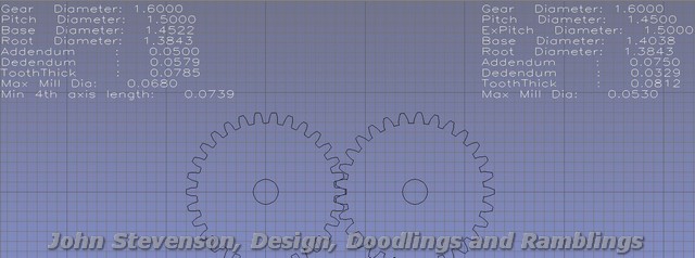
Now lets take Simon's 29T special gear.
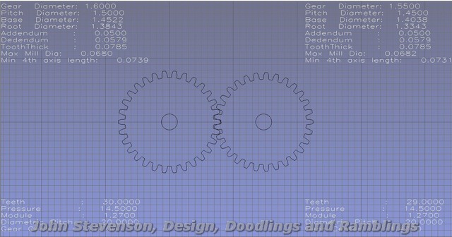
Standard 30 T on the left, 29T on the right, both standard at 20DP and 14.5 pressure angle. There is virtually no difference in shape as these would have been cut with the same FORMED cutter but these shapes are GENERATED. The important bit is the 30T has an OD of 1.600" and the 29 has an OD of 1.550" but Simon needs it to have an OD the same as the 30T so it meshes correctly. So we correct the gear by moving the relationship of the Addendum and Dedendum [ top bit of the gear above the pitch line and bottom bit of the gear below the pitch line ] and we get this.
Now both OD's are the same but now look at the shape of the tooth. Because 29 teeth have been spread out where 30 should be they now have fatter stronger teeth but unfortunately you can't use the standard No 4 cutter or you just finish up with the same shape at the 30 T.
End of this post. I need a coffee and I reckon the cat is still outside. More later.
|
| John Stevenson | 20/03/2017 23:52:44 |
5068 forum posts 3 photos | Couple of corrections first Accuracy** the ** was meant to be a note to say working tolerances in a home shop and ignoring the armchair machinists and angels on pin heads.
Chinese cutters are often Banded 1 to 8 the same but in reverse order so be careful when reading descriptions.
Now how to do the corrections. As usual, many ways and it depends on equipment to hand, skill levels and the price of fish.
The most accurate** way would be to save the drawing of the new gear as a DXF, blow it up and transpose two circles onto the involute flanks and then the relevant date of diameters and distance between can be taken direct from the drawing and a button cutter made than in turn is used to make a form cutter.
Next way would be to cut one tooth space out as a template and then go though a massive stack of gear cutters to find one that fits the gap best. Only applies IF you have a massive stack of gear cutters.
However most people only have a few, usually pst of the 8 band as they feel 12T and racks are beyond thier pay grade. So we will take a look at this method. Again it can be calculated but if you find it's something that might come in handy from time to time then it's worth spending 1/2 a night just drawing one tooth in in the 8 bands. Doesn't matter what DP as they can be scaled.
The red is Simon's corrected gear, the green is one tooth of the next band down, the No 5 and has been sunk into the blank 3 thou deeper than standard so the main flanks of the gear match the corrected gear. Because the band is one lower there is more undercut but as gears work more on the addendum that the dedendum for what it is need for , it will be perfectly fine.
It is also possible to be this mathematically but TBH the hands on paste and drag is far quicker and gives the same results.
That's it for tonight as both me and hound need our cheese and biscuits. He's a very discerning hound, best stilton for him, no mousetrap. |
| Simon Williams 3 | 20/03/2017 23:57:43 |
| 728 forum posts 90 photos | John - thank you for an impressive piece of work. I stand in awe of the expertise. I'm hoping tomorrow to make the 16 1/2 tooth gear I promised you. Watch this space.
Rgds to you and the hound (hope he hasn't been chasing my cat!) Simon |
| Allan B | 21/03/2017 00:01:11 |
133 forum posts 23 photos | John, that information is wonderful, gear cutting is my next learning project after I get my head round screws so I might print this lot out if you don't mind so I can keep it for reference. Allan |

Please login to post a reply.
Magazine Locator
Want the latest issue of Model Engineer or Model Engineers' Workshop? Use our magazine locator links to find your nearest stockist!
Sign up to our Newsletter
Sign up to our newsletter and get a free digital issue.
You can unsubscribe at anytime. View our privacy policy at www.mortons.co.uk/privacy
Latest Forum Posts
- *Oct 2023: FORUM MIGRATION TIMELINE*
05/10/2023 07:57:11 - Making ER11 collet chuck
05/10/2023 07:56:24 - What did you do today? 2023
05/10/2023 07:25:01 - Orrery
05/10/2023 06:00:41 - Wera hand-tools
05/10/2023 05:47:07 - New member
05/10/2023 04:40:11 - Problems with external pot on at1 vfd
05/10/2023 00:06:32 - Drain plug
04/10/2023 23:36:17 - digi phase converter for 10 machines.....
04/10/2023 23:13:48 - Winter Storage Of Locomotives
04/10/2023 21:02:11 - More Latest Posts...
- View All Topics
Support Our Partners


Shopping Partners
Subscription Offer

Latest "For Sale" Ads
- Reeves** - Rebuilt Royal Scot by Martin Evans
by John Broughton
£300.00 - BRITANNIA 5" GAUGE James Perrier
by Jon Seabright 1
£2,500.00 - Drill Grinder - for restoration
by Nigel Graham 2
£0.00 - WARCO WM18 MILLING MACHINE
by Alex Chudley
£1,200.00 - MYFORD SUPER 7 LATHE
by Alex Chudley
£2,000.00 - More "For Sale" Ads...
Latest "Wanted" Ads
- D1-3 backplate
by Michael Horley
Price Not Specified - fixed steady for a Colchester bantam mark1 800
by George Jervis
Price Not Specified - lbsc pansy
by JACK SIDEBOTHAM
Price Not Specified - Pratt Burnerd multifit chuck key.
by Tim Riome
Price Not Specified - BANDSAW BLADE WELDER
by HUGH
Price Not Specified - More "Wanted" Ads...
Get In Touch!
Do you want to contact the Model Engineer and Model Engineers' Workshop team?
You can contact us by phone, mail or email about the magazines including becoming a contributor, submitting reader's letters or making queries about articles. You can also get in touch about this website, advertising or other general issues.
Click THIS LINK for full contact details.
For subscription issues please see THIS LINK.
Digital Back Issues


Donate

 Register
 Log-in
Model Engineer Magazine
- Percival Marshall
- M.E. History
- LittleLEC
- M.E. Clock

ME Workshop
- An Adcock
- & Shipley
- Horizontal
- Mill

Subscribe Now
- Great savings
- Delivered to your door

Pre-order your copy!
- Delivered to your doorstep!
- Free UK delivery!
All Forum Topics > Beginners questions > Myford Super 7 screw cutting gears (metric)