Forum sponsored by:

Stuart Twin Victoria (Princess Royal) Mill Engine
| Dr_GMJN | 11/08/2021 22:54:14 |
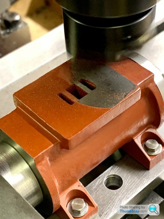
 1602 forum posts | I set up the mandrel as suggested, with snug supports under the overhanging foot plates, but not clamped. I did rebate the rear of the mating boss a bit after all: |
| Dr_GMJN | 14/08/2021 17:52:15 |
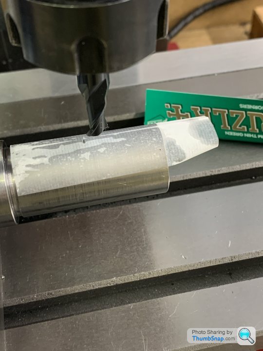
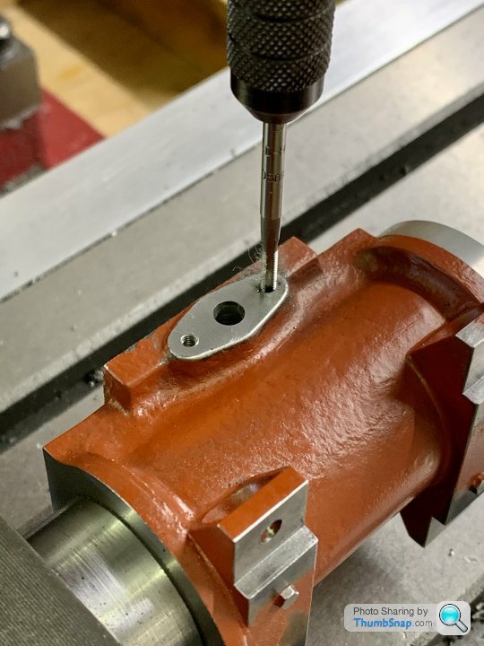
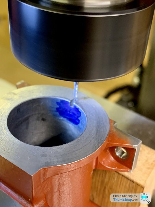
1602 forum posts | Always wanted to try using Rizla paper to find the surface of something, 0.0005” according to the verniers, so there we go… |
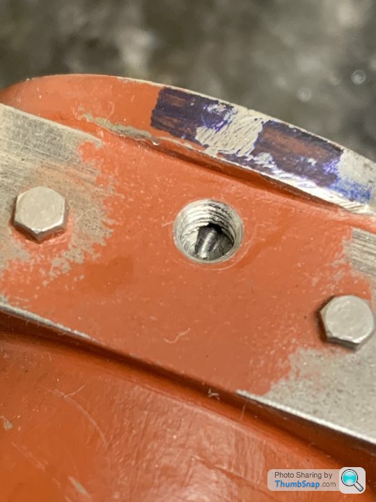
| Dr_GMJN | 30/08/2021 18:51:05 |
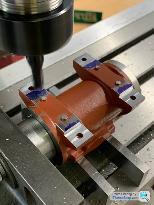
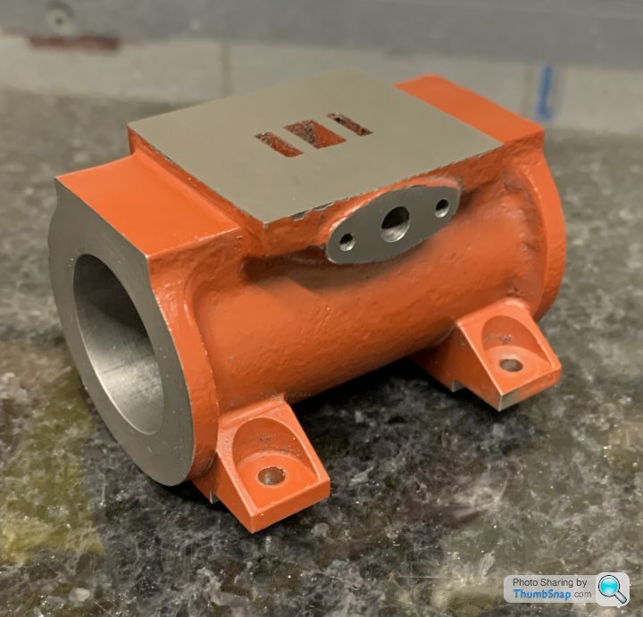
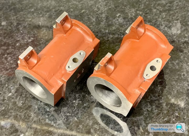
1602 forum posts | Struggling with motivation do to anything at the moment - maybe I’ve got too many projects on, or maybe it’s delayed lockdown blues. Anyway, got the other cylinder exhaust port and feet done: |
| JasonB | 30/08/2021 20:04:25 |
 25215 forum posts 3105 photos 1 articles | I've never found the need to do the separate CSK screws to hold the chest in place, I always just use the studs that run right through and retain the cover. Easy enough to slip a couple of larger nuts over two studs to act as spacers so the chest can be held in place when the eccentric rod length is being set then no need to be able to hold the chest without cover after that. If you still want to go with them then I don't see the need for them being 4BA, get some M2.5 or even M3 CSK socket screws and use those. |
| Dr_GMJN | 30/08/2021 20:31:39 |
1602 forum posts | Posted by JasonB on 30/08/2021 20:04:25:
I've never found the need to do the separate CSK screws to hold the chest in place, I always just use the studs that run right through and retain the cover. Easy enough to slip a couple of larger nuts over two studs to act as spacers so the chest can be held in place when the eccentric rod length is being set then no need to be able to hold the chest without cover after that. If you still want to go with them then I don't see the need for them being 4BA, get some M2.5 or even M3 CSK socket screws and use those. Yes it did seem a bit odd putting an extra four holes there, but I guess I'll do it anyway since it's per the instructions. I'll see what I've got in smaller sizes and use those like you suggest. As for drilling the holes themselves, intention is to get the centreline of the casting from the mandrel, and use that as a left/right offset. Front/back will be from the exhaust port hole (which I've previously determined is in the centre of the face, and it matches exactly with the cast-in ports). I'll then drill that same offset pattern in the housing, using the rod holes as a centreline datum. Also, I think the actual valve face is too small (according to the drawings), yet the un-machined valve chest casting seems to correspond very nicely to it. I guess all the holes therefore need offsetting slightly towards the middle? Thanks. |
| JasonB | 31/08/2021 08:17:01 |
25215 forum posts 3105 photos 1 articles | Mine ended up being 1.348" wide rather than 1 3/8" so I just reduced the hole positions by the same amount to maintain the same edge distance, all set out from ctr lines. |
| Dr_GMJN | 31/08/2021 10:55:02 |
1602 forum posts | Posted by JasonB on 31/08/2021 08:17:01:
Mine ended up being 1.348" wide rather than 1 3/8" so I just reduced the hole positions by the same amount to maintain the same edge distance, all set out from ctr lines.
So the boss for the packing is oval, and the sides of the chest need to be equi-distant from the central hole in the oval. I'm thinking get the centre of the oval, centre drill it, then somehow clean up the long sides on the mill, equi-distant from the centre hole, then do the offsets for the square faces, then set in the 4-jaw to finally drill the valve rod holes and clean up the end dome? Question is what order to do this in and how to get the equi-distant faces. I don't have a vernier height gauge. I'm wary of setting up non-machined faces in the 4-jaw, since I suppose I could get a skewed hole? |
| JasonB | 31/08/2021 16:13:37 |
25215 forum posts 3105 photos 1 articles | I think I just worked out which was going to be the narrowest of the three parts and reworked the hole positions to suit that. Set them up in the vice and located ctr of each and used the DRO to layout the holes then screwed them together and milled the sides so all were flush. You then have straight sides if you need to tidy up the dome. Looks like I did the gland and rod hole sin the mill, screwed on the gland and then filed the boss and gland to a similar profile. The glands were missing from the engine I got so knocked up a couple on the CNC and also cleaned up the pipe flanges in the same way.
|
| Dr_GMJN | 31/08/2021 18:57:58 |
1602 forum posts | How did you mill all the sides flush? One has the dome in the way, one has the oval in the way and the other has the exhaust port on the cylinder in the way. Do you mean the cover to chest, or chest to cylinder or all three together? |
| JasonB | 31/08/2021 19:15:04 |
25215 forum posts 3105 photos 1 articles | Sides were done with a 50mm insert cutter, one side simple the other just taken as close as possible to the exhaust boss then finished with a file to blend boss into milled surface.
You can see from the above that the chest was the shortest so not really anything to come off it's ends. With assembly in the vice cover facing upwards I milled the ends of the cover until they just came flush with the chest and noted the DRO positions. Then removed chest & cover so that the port face could be milled to those dimensions, probably used a 10mm cutter for that, Filed the last bits of the port face ends where they are below the flats on the top of the cylinders.
|
| Dr_GMJN | 31/08/2021 23:02:29 |
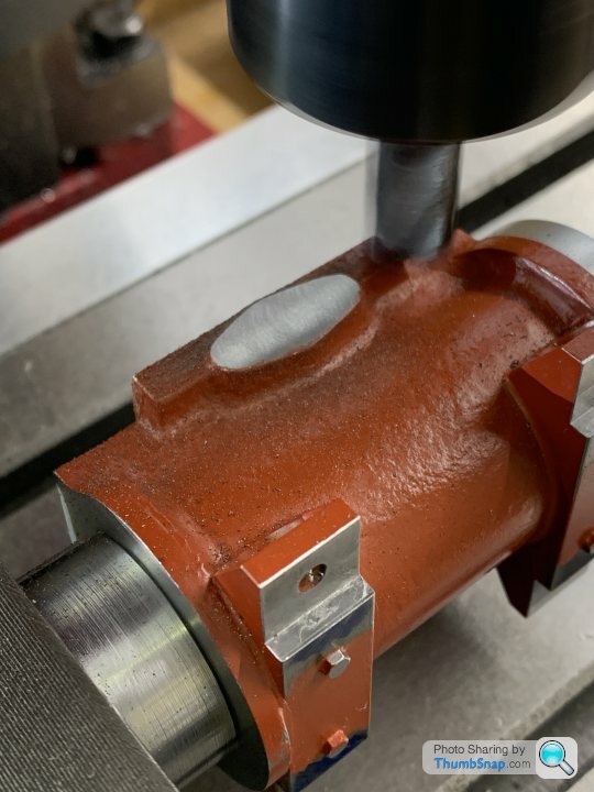
1602 forum posts | Thanks Jason. My intention - at present - is to paint the sides of the valve chest, and the sides of the cylinder valve face, but leave the edges and top periphery of the cover plate bright (recessed centre painted too). I think it might look ok like that, especially with the gasket line demarcations and the bright inlet block on the side as a contrast. So I think I’ll first fully machine the chest faces to depth, minimally machine the sides to clean up (there’s the inlet port on one side so it needs doing flat), minimally machine up the dome end in the 4-jaw, and file and flat the packing gland end by hand. If it then turns out short to fit to the cylinder valve face, Ill file the ends of the face to match. |
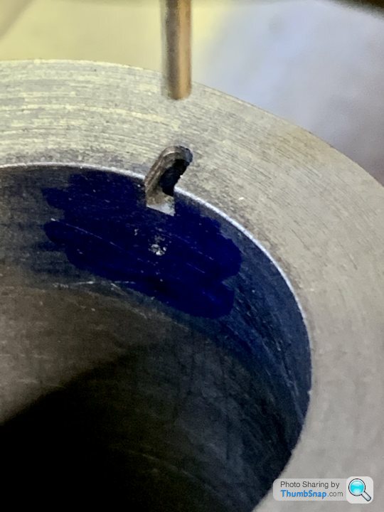
| Dr_GMJN | 03/09/2021 12:14:42 |
1602 forum posts | I did some minor tidying up around the feet, and drilled and tapped the cylinder drain cock holes as per the instructions: |
| JasonB | 03/09/2021 13:27:47 |
25215 forum posts 3105 photos 1 articles | It's not critical that the holes go right to the very end of the cylinder, any condensate will tend to be blown out between the gap around the piston either side of the rings/packing. Simple way to do it is to drill in from the tapped hole either straight or at whatever angle you can get, even starting where bottom meets side of hole will work and help the drill start.
If you really want to get it right upto the spigots on the covers than rather than try and drill an angled hole like you show just use a 1.5mm milling cutter to make a small "D" shaped notch say 2.5mm deep so it extends beyond the cover's spigot
A ctr drill will only be slightly more useful than a standard drill at starting on an angle, less so the steeper the angle or longer the ctr drill. Better to gently plunge with a flat or ball nosed milling cutter to give the drill somewhere to start |
| Dr_GMJN | 03/09/2021 14:25:08 |
1602 forum posts | Thanks Jason. I'll go with the 1.5mm end mill method (similar to the 10V geometry IIRC). I've just got that sized milling cutter for the car differential output spigot job. Let's hope it survives... |
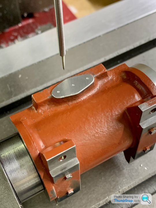
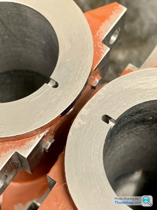
| Dr_GMJN | 04/09/2021 11:47:07 |
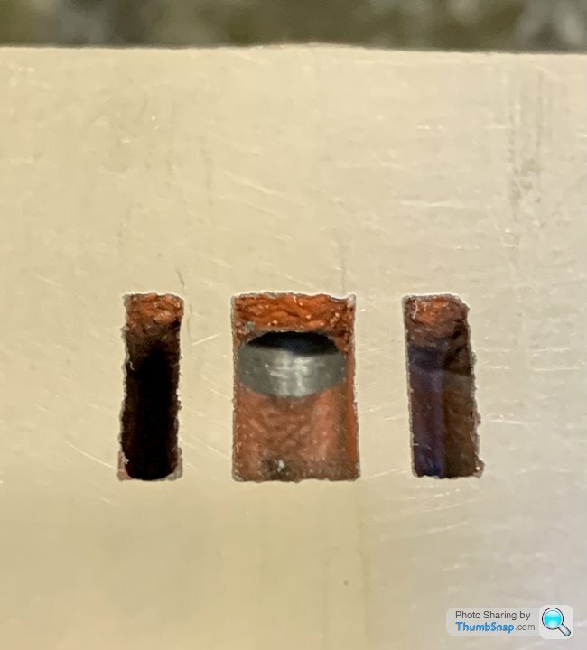
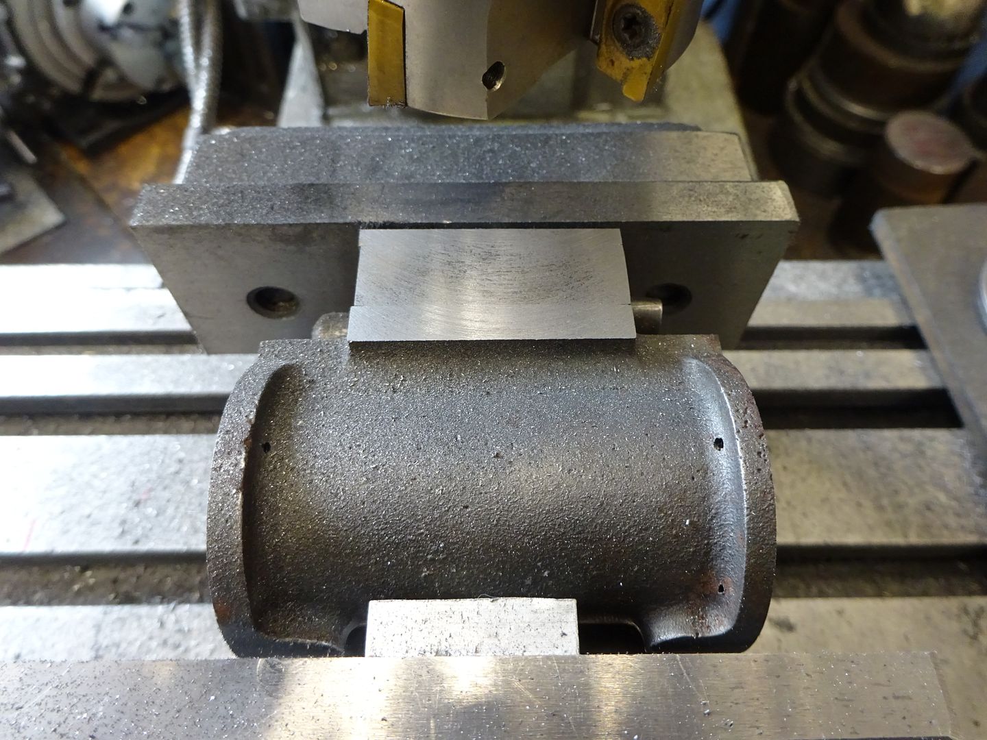
1602 forum posts | Milled and drilled the 1.5 mm cylinder condensate drain holes as per above this morning: |
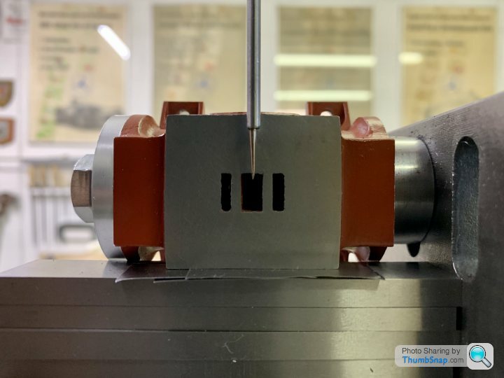
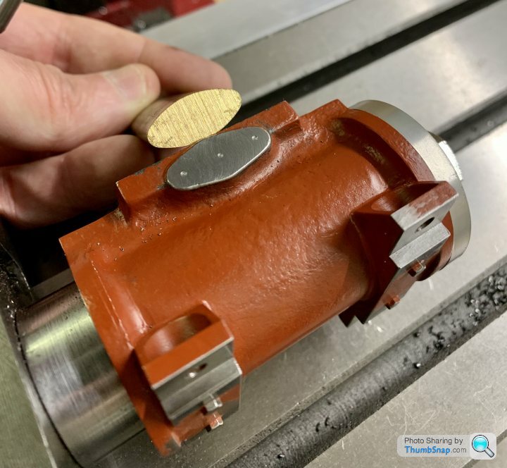
| Dr_GMJN | 04/09/2021 12:52:21 |
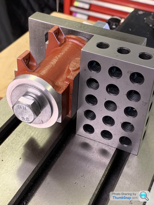
1602 forum posts |
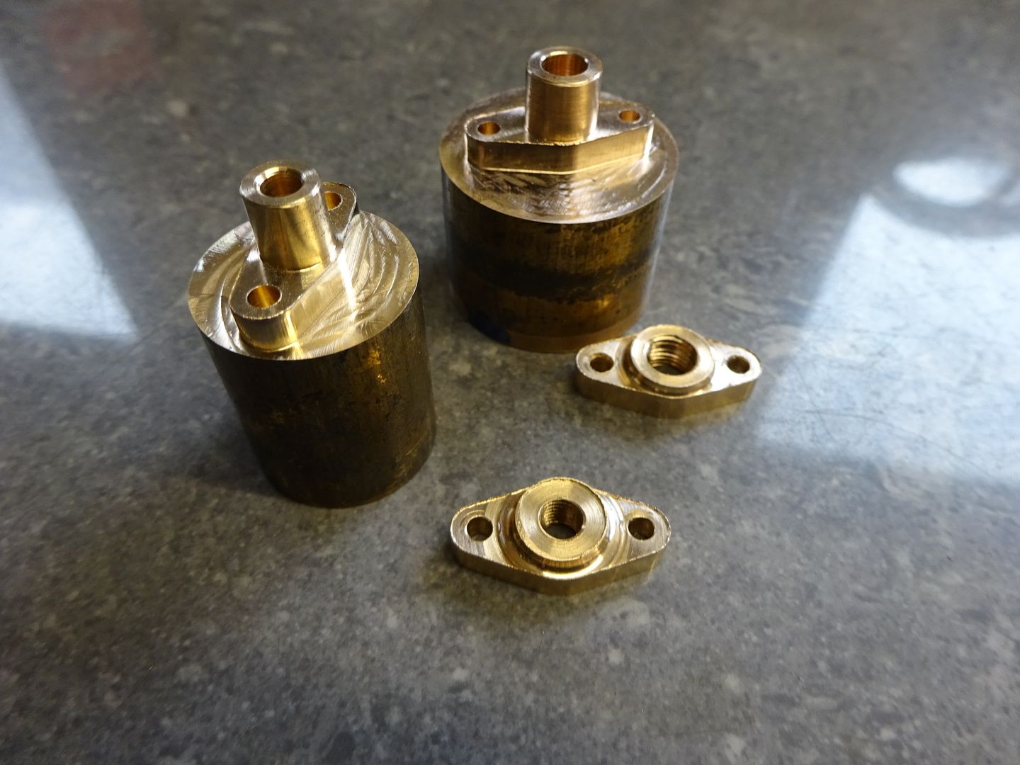
I’ve got this profiled brass/gunmetal for the packing glands and the exhaust ports. They all need drilling centrally, and then two holes for studs each side:
|
| JasonB | 04/09/2021 13:29:25 |
25215 forum posts 3105 photos 1 articles | You can set the extrusion up in the 4 jaw checking opposite sides are central and then face and turn the raised central boss. Once turned blue the end with a sharpie and use your new height gauge set to lathe ctr height to scribe a couple of lines either side of the boss when the extrusion looks horizontal in the chuck, Square against a chuck jaw can help. Then increase height gauge setting to include half the stud hole spacing, rotate chuck 90deg and scribe one line, rotate 180deg and do the other. part off and repeat for the others. Carefully punch and then drill the stud holes. Valve chest. File off the casting sprue, blue and mark out position of hole again height gauge make sit easy to do the offset height then measure overall width, half that and set gauge to that so you can mark it's position width wise and punch where the lines meet. Set up in 4-jaw so the punch mark runs true, face, drill, ream, countebore and drill the far end then mark out as for the glands or back into mill vice, locate ctr of hole and just use DRO to get the position of the two stud holes. Yes screw them on and file to suit Back to the Cylinders, have you gone deep enough with those notches? they need to be deeper than the 1/16" spigots on the cylinder covers unless you are going to machine clearance on the spigots. |
| Dr_GMJN | 04/09/2021 15:42:09 |
1602 forum posts | Thanks Jason, so the extrusion in the 4- jaw is just aligned in the jaws by eye? The drain slot extends 2mm into the cylinder, and the spigot is 1.6mm deep minus the gasket, so that should give about a 0.5mm gap. Is that enough? Could pocket the caps a bit, but since I doubt it will ever run in steam it might not matter. |
| JasonB | 04/09/2021 16:19:25 |
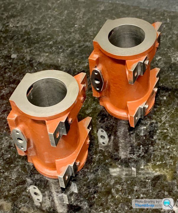
25215 forum posts 3105 photos 1 articles | As you are going to end up filing most of the extrusion's edges to match the CI bosses lining up with the jaws by eye should be fine unless you don't have a good eye for that sort of thing. the problem is that they used to supply castings rather than the extrusion and they were more like the shape of the iron bosses which are really 3 circles and 4 tangental edges. If you get your rotary table then that type of shape is quite easy to mill so you could bolt on the flanges and locate the two parts under the mill spindle and machine to a nice shape. This is what I machined the flanges too and the iron bosses only needed a very small amount of file work to match
|
| Dr_GMJN | 04/09/2021 16:55:39 |
1602 forum posts | Ok I’ll have a look at milling to profile when I get the table. The shape you drew would appear to need two setups - 1) to get the central large radii and tangent edges, 2) The the part would need offsetting on the table to centre the two outer radii? |


Please login to post a reply.
Magazine Locator
Want the latest issue of Model Engineer or Model Engineers' Workshop? Use our magazine locator links to find your nearest stockist!
Sign up to our Newsletter
Sign up to our newsletter and get a free digital issue.
You can unsubscribe at anytime. View our privacy policy at www.mortons.co.uk/privacy
Latest Forum Posts
- hemingway ball turner
04/07/2025 14:40:26 - *Oct 2023: FORUM MIGRATION TIMELINE*
05/10/2023 07:57:11 - Making ER11 collet chuck
05/10/2023 07:56:24 - What did you do today? 2023
05/10/2023 07:25:01 - Orrery
05/10/2023 06:00:41 - Wera hand-tools
05/10/2023 05:47:07 - New member
05/10/2023 04:40:11 - Problems with external pot on at1 vfd
05/10/2023 00:06:32 - Drain plug
04/10/2023 23:36:17 - digi phase converter for 10 machines.....
04/10/2023 23:13:48 - More Latest Posts...
- View All Topics
Support Our Partners


Shopping Partners
Subscription Offer

Latest "For Sale" Ads
- Reeves** - Rebuilt Royal Scot by Martin Evans
by John Broughton
£300.00 - BRITANNIA 5" GAUGE James Perrier
by Jon Seabright 1
£2,500.00 - Drill Grinder - for restoration
by Nigel Graham 2
£0.00 - WARCO WM18 MILLING MACHINE
by Alex Chudley
£1,200.00 - MYFORD SUPER 7 LATHE
by Alex Chudley
£2,000.00 - More "For Sale" Ads...
Latest "Wanted" Ads
- D1-3 backplate
by Michael Horley
Price Not Specified - fixed steady for a Colchester bantam mark1 800
by George Jervis
Price Not Specified - lbsc pansy
by JACK SIDEBOTHAM
Price Not Specified - Pratt Burnerd multifit chuck key.
by Tim Riome
Price Not Specified - BANDSAW BLADE WELDER
by HUGH
Price Not Specified - More "Wanted" Ads...
Get In Touch!
Do you want to contact the Model Engineer and Model Engineers' Workshop team?
You can contact us by phone, mail or email about the magazines including becoming a contributor, submitting reader's letters or making queries about articles. You can also get in touch about this website, advertising or other general issues.
Click THIS LINK for full contact details.
For subscription issues please see THIS LINK.
Digital Back Issues


Donate

 Register
 Log-in
Model Engineer Magazine
- Percival Marshall
- M.E. History
- LittleLEC
- M.E. Clock

ME Workshop
- An Adcock
- & Shipley
- Horizontal
- Mill

Subscribe Now
- Great savings
- Delivered to your door

Pre-order your copy!
- Delivered to your doorstep!
- Free UK delivery!
All Forum Topics > Work In Progress and completed items > Stuart Twin Victoria (Princess Royal) Mill Engine