Forum sponsored by:

Information on digital angle gauge.
Information that may allow them to be used for other purposes
| Michael Gilligan | 24/03/2014 22:44:10 |
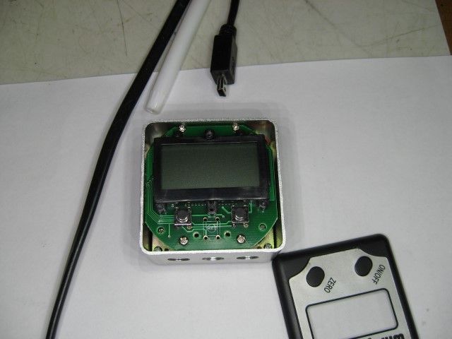
 23121 forum posts 1360 photos | Les, Looking at your image 0493(custom) ... the location for a third switch is evident on the PCB This would presumably be for the Hold Function, on the "with-bubble-level" version [which, I note, looks reassuringly similar to the CPC/Duratool one]. I would think there may be room for another small switch [isolated from the board] at that location. MichaelG. |
| Involute Curve | 24/03/2014 23:21:08 |
 337 forum posts 107 photos | Just a thought, do you think these could be used as encoders to make a digitising arm? |
| Michael Gilligan | 24/03/2014 23:39:18 |
23121 forum posts 1360 photos | Posted by Involute Curve on 24/03/2014 23:21:08:
Just a thought, do you think these could be used as encoders to make a digitising arm? . Excellent idea ... Something like this MichaelG. Edited By Michael Gilligan on 24/03/2014 23:44:24 |
| Involute Curve | 25/03/2014 00:04:39 |
337 forum posts 107 photos | Yep like that, and I'm sure Mach and EMC etc can take input from external data source, in a similar manner that it takes data from a probe and then create a point cloud, I remember reading somewhere, I think on CNC zone about DIY scanning arm's, however they where having problems with quadratic encoders, not functionally but getting hold of them at reasonable prices, perhaps these devices could be an alternative approach. I need to give this some more thought.......... I feel a distraction coming on Edited By Involute Curve on 25/03/2014 00:07:47 |
| Les Jones 1 | 25/03/2014 08:57:13 |
| 2292 forum posts 159 photos | Hi Michael, Les. |
| Les Jones 1 | 25/03/2014 09:20:00 |
| 2292 forum posts 159 photos | Hi Involute Curve, Les. |
| Involute Curve | 25/03/2014 11:43:08 |
337 forum posts 107 photos | Here's a link to the page I read http://www.cnczone.com/forums/digitizing-laser-digitizing/4424-digitizing-arm-options.html
Shaun
|
| Neil Wyatt | 25/03/2014 17:20:45 |
 19226 forum posts 749 photos 86 articles | > It turned out it was 504 counts per rev. You can imagine the designer sniggering "This one will fox the skip-monkeys!" Neil |
| Les Jones 1 | 07/04/2014 20:46:46 |
| 2292 forum posts 159 photos | I have found out that I made a mistake with the original information I gave about the angle gauges. I was 1 bit position out. This is the corrected information. Les. |
| Les Jones 1 | 13/04/2014 14:42:56 |
| 2292 forum posts 159 photos | Hi all, Les. |
| Michael Gilligan | 13/04/2014 15:05:12 |
23121 forum posts 1360 photos | Thanks, Les MichaelG. |
| Nathan Brawner | 21/11/2014 17:20:35 |
| 1 forum posts | Hello Les, I am looking to display my Wixey angle gauge on either an LCD or display on my laptop for a project. Any advise on how to get started with deciferring the data? I don't have much experience with data as I have just began to study it. Thank you for any help provided. -Nathan
|

Please login to post a reply.
Magazine Locator
Want the latest issue of Model Engineer or Model Engineers' Workshop? Use our magazine locator links to find your nearest stockist!
Sign up to our Newsletter
Sign up to our newsletter and get a free digital issue.
You can unsubscribe at anytime. View our privacy policy at www.mortons.co.uk/privacy
Latest Forum Posts
- hemingway ball turner
04/07/2025 14:40:26 - *Oct 2023: FORUM MIGRATION TIMELINE*
05/10/2023 07:57:11 - Making ER11 collet chuck
05/10/2023 07:56:24 - What did you do today? 2023
05/10/2023 07:25:01 - Orrery
05/10/2023 06:00:41 - Wera hand-tools
05/10/2023 05:47:07 - New member
05/10/2023 04:40:11 - Problems with external pot on at1 vfd
05/10/2023 00:06:32 - Drain plug
04/10/2023 23:36:17 - digi phase converter for 10 machines.....
04/10/2023 23:13:48 - More Latest Posts...
- View All Topics
Support Our Partners


Shopping Partners
Subscription Offer

Latest "For Sale" Ads
- Reeves** - Rebuilt Royal Scot by Martin Evans
by John Broughton
£300.00 - BRITANNIA 5" GAUGE James Perrier
by Jon Seabright 1
£2,500.00 - Drill Grinder - for restoration
by Nigel Graham 2
£0.00 - WARCO WM18 MILLING MACHINE
by Alex Chudley
£1,200.00 - MYFORD SUPER 7 LATHE
by Alex Chudley
£2,000.00 - More "For Sale" Ads...
Latest "Wanted" Ads
- D1-3 backplate
by Michael Horley
Price Not Specified - fixed steady for a Colchester bantam mark1 800
by George Jervis
Price Not Specified - lbsc pansy
by JACK SIDEBOTHAM
Price Not Specified - Pratt Burnerd multifit chuck key.
by Tim Riome
Price Not Specified - BANDSAW BLADE WELDER
by HUGH
Price Not Specified - More "Wanted" Ads...
Get In Touch!
Do you want to contact the Model Engineer and Model Engineers' Workshop team?
You can contact us by phone, mail or email about the magazines including becoming a contributor, submitting reader's letters or making queries about articles. You can also get in touch about this website, advertising or other general issues.
Click THIS LINK for full contact details.
For subscription issues please see THIS LINK.
Digital Back Issues


Donate

 Register
 Log-in
Model Engineer Magazine
- Percival Marshall
- M.E. History
- LittleLEC
- M.E. Clock

ME Workshop
- An Adcock
- & Shipley
- Horizontal
- Mill

Subscribe Now
- Great savings
- Delivered to your door

Pre-order your copy!
- Delivered to your doorstep!
- Free UK delivery!
All Forum Topics > Hints And Tips for model engineers > Information on digital angle gauge.