Forum sponsored by:

Harold Hall QTCP, MEW 50, any one using it?
| Peter E | 09/12/2010 23:04:02 |
| 48 forum posts 22 photos | Reading through the thread I noticed that also another type of QCTP was mentioned, namely the type having a cylindrical tool post with tool holders nipping the post. I made that type for my first lathe, a Unimat clone called MJ-189. A really good little lathe once it was adjusted. After using it for a while I got fed up with keeping track of all the packing pieces to get the cutting tools at proper height. I then made a cylindrical toolpost from a 35 mm dia piece of BMS turning the main part down to 20 mm. The result was a 20 mm dia post with a 35 mm dia foot. The tool holders were made from 15x30 mm BMS in 40 mm lengths. A 20 mm hole drilled/bored in its center and slitted for nipping to the post using a 6 mm cap screw. I found two pics showing two types of tool holders, one for ordinary turning and one for boring.  and  As can be seen, I tried out ordinary screws for clamping as well as a screw with a lever handle. The slit-and-nip works very good, but if I were to make more of these now I would go for a brass clamping dog pulled by the screw and not use a slitted holder. The internal clamping dog does a much better job of clamping with less force when locking. My experience of this type was generally very good. The circular tool post gave perfect support at any angle of the tool, something that the original rectangular holder did not do. But for the C3, it will be the dovetail style stuff. Regards /Peter E |
| Clive Foster | 10/12/2010 11:54:29 |
| 3630 forum posts 128 photos | Given the inevitable budget constraints, both fiscal and temporal, concerning Home Shop and Hobby activities I think there is much to be said for a system based on interchanging tool bits in nominally fixed Armstrong type holders. Provided of course that your lathe is large enough to accept Armstrong holders which may rule out anything below about 3" centre height unless the top slide is removed. Because the Armstrong holder mounts the tool bit with an upwards slope setting the bit to centre height also sets its projection to close limits. The optical centre height gauge described by Ted Wale in the November 2004 issue of Model Engineers Workshop is by far the best type, especially in this sort of application. I was familiar with the principle for many years previous to Teds description but never felt it would be enough better than what I was using to make one. Needing a new gauge to suit my Smart & Brown 1024 I finally got round to it and seriously regretted a quarter of a century doing things the usual way. Square tool steel is inexpensive compared to inserts and butt welded, forged shank tooling so its economically feasible to have a good range of bits ground to appropriate angles making it pretty much unnecessary to adjust the tool holder position in normal work. Grinding square tool bits to accurately repeatable shape needs only simple angle setting jigging. Some of the but welded tools can be a right pain with limited facilities.
Clearly a simple two slot block will suffice to carry the normal turning, bent to the right, holder and the face turning, bent to the left, holder. Simple stops to set the 180° rotation needed for interchange should be no great problem. Such blocks can be bolted up from stock sections. Similar holders will clearly suffice for parting tools and any insert tooling you may choose to use. If you use the common "mutant golf club" boring and internal threading tool forms hated by Geo.H.Thomas shimming must be resorted to. His eccentric holder and boring bar system would work well given a suitable block. Given a Tee slotted top slide switching blocks becomes trivial if complete assemblies with locking handles and Tee nut are made. In my South-Bend driving days I had multiple four ways made up in this manner carrying but welded tools which worked well save for the usual shimming tedium. The normal nut on a stud system shouldn't be impossibly tedious but, if so, there are various ways of arranging quick release. For example the centre stud could be arranged to be freely rotating with a cross hole drilled close to the top for a locking handle in the form of along pin. If an externally threaded sleeve with a castellated top is screwed into the tool block the locking handle can be passed between the castellations and though the hole in the stud. It should be no great problem to arrange matters so that third of a turn or so goes from locked to loose enough for the handle to be withdrawn and the block lifted away.
Obviously considerable refinements of the basic idea covering, for example, indexing et al are possible to suit individual needs. Clearly it works just as well with insert holders if pre-loaded blocks are interchanged.
Clive |
| Bill Pudney | 10/12/2010 21:51:21 |
| 622 forum posts 24 photos | Whats an "Armstrong type holder" A picture speaks a thousand words Bill Pudney |
| Harold Hall 1 | 10/12/2010 22:28:39 |
| 418 forum posts 4 photos | The brief answer to Goran's original question is Yes, I have, but looking at my name that should be obvious. Those who read my articles in MEW will have seen very many illustrations of it being used. I do not though think mine is the be all and end all in QCTH design but as Bill Pudney comments it shows that there's more than one way to skin a cat!! A few comments about the design may be of interest to those coming to this thread. The original was developed to limit the amount of milling required firstly to minimise the time taken to make them and secondly making it practical for those who only have a lathe and drilling machine. The time element should be obvious as drilling a hole through two holders clamped back to back will take no more than a few minutes, milling dovetails on two holders would take considerably more, perhaps a half an hour. If one intends to make a large number of holders that is a considerable saving. I would though recommend the hole to be reamed as drilled holes can be a little barrel shaped, though mine work adequately. A technical aspect of the design is that the length to width ratio of the half round location is around 4 to 1 whilst most dovetail holders this will be around 1to1 maybe less. This should make it pull into place more precisely but there are other considerations. If you are unsure, consider a longish piece of 10mm diameter held in the three jaw to a depth of 10mm, then place it in 40mm, I know which will be running more accurately at its end. Of course, with commercially made dovetail holders having a good finish, may be ground and hardened then they will move more freely over the two mating surfaces than ones made in the average home workshop. Of course if power feed to the milling machine table is available then it will be less of a problem but hand feed will cause furrows if the feed is slowed or even stopped. It was also suggest that a square key to be used but the two curved surfaces coming together act as a mini inverted dovetail whereas the corners of a square would tend to dig in. If I where making a set again with the experience gained I would just ream my drilled holes that make the locations and increase the throw of the clamping cam by just a little, though I think I have included this in the drawings on my web site. I do not normally visit the forum, I do not have the time, but will keep my eye on this thread should any comments need answering. |
| Clive Foster | 11/12/2010 20:01:13 |
| 3630 forum posts 128 photos | Hi Bill
As requested a picture of the two "bent" styes of Armstrong type holder posed next to a round bar at more or less operating angle. Various sizes and similar but different styles depending on maker. These are for 1/4 square tool bits, shanks on these are nominal 1" high and typically the sharp end will be about 5/8 to 3/4 above the support surface. Usually the bit axis will be 90° to the work with any special shaping ground on the tip. A 3" stick of HSS will usually do for 2 double ended bits.
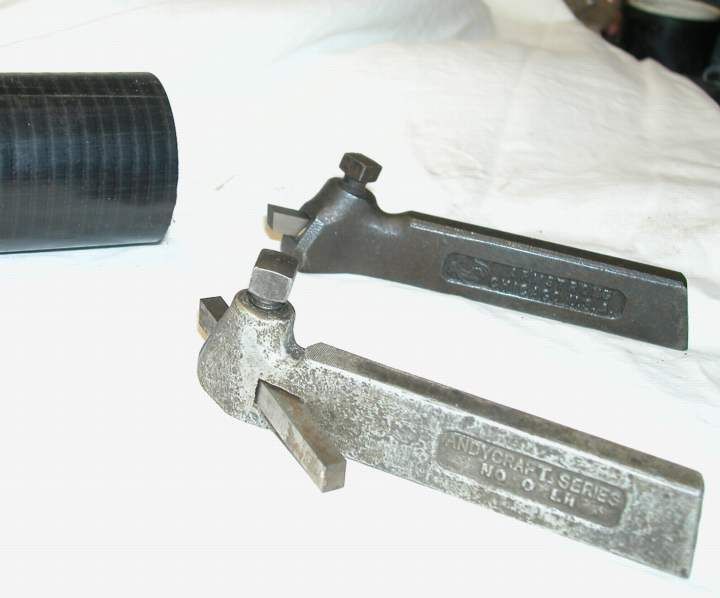 Hope this helps.
Clive |
| John Olsen | 11/12/2010 23:50:00 |
| 1294 forum posts 108 photos 1 articles | When I inherited my Myford it came with toolholders in the above style. The problem with them is that the amount of overhang gives good leverage for the cutting forces to shift the toolholder on the topslide. If you tighten up the toolpost nut to prevent this, it distorts the topslide, making it tight on its slide. This is of course a Myford shortcoming rather than the fault of the toolholders themselves. Similar toolholders were made without the built in rake for use on shapers, and they are very useful there. regards John |
| Bill Pudney | 15/12/2010 01:03:08 |
| 622 forum posts 24 photos | Now I know, I've seen and used those, I just never associated them with "Armstrong". One of the reasons for doing what I did was to reduce overhang, both of parting off and cutting tools. The Sieg C3 is not the most rigid of lathes and anything to help increase rigidity is welcome. cheers Bill Pudney |
| ady | 15/12/2010 03:12:30 |
| 612 forum posts 50 photos | Reading through the thread I noticed that also another type of QCTP was
mentioned, namely the type having a cylindrical tool post with tool
holders nipping the post. The old Drummonds used them, they are called Norman's Patent.  The round post in the middle also has a deep thread which takes a (very rare now) indexing milling and gearcutting unit, so it was mounted directly on the compound. A standard Drummond lathe and cast iron stand cost about 26quid, and if you wanted it, the gearcutting arrangement would cost you 30...so there aint many around. |
| ady | 15/12/2010 03:42:50 |
| 612 forum posts 50 photos | I haven't read the thread but I suppose I should mention that the simplest QCTP is a rear toolpost.
A one eighth tool 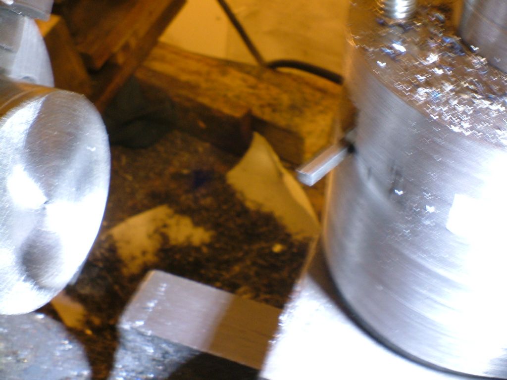 And a half inch tool 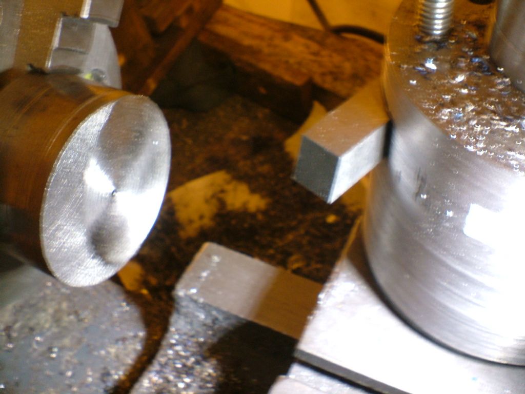 Those of us with a reals mans lathe, like a Drummond with a slotted cross slide, can do these things. Edited By ady on 15/12/2010 03:46:57 |
| John Olsen | 15/12/2010 04:49:20 |
| 1294 forum posts 108 photos 1 articles | Bill, I suspect Armstrong was a maker, although the ones I have are mostly Jones and Shipman. The one exception is a parting tool holder by Ace. (Not to be confused with Acme, suppliers of dynamite to the Roadrunner ) The only one I have with the zero rake for a shaper is slightly too big to fit the toolpost on my 18 inch Alba. I wonder what sort of giant machine it would fit? It may yet get a few minutes on the other side of the shaper to make it useful, as other than the size of the shank it would be about right. regards John |
| Clive Foster | 15/12/2010 11:57:26 |
| 3630 forum posts 128 photos | Bill, John
Armstrong from Armstrong Patent, which they were marketed as for many years. Armstrong invented the beast and took out several patents from around the mid 1890's to mid 1920's. Don't know the specific patented features tho' although the idea of pointing the tool upwards at a generic "little too large" rake angle was clearly important for easy grinding and tool material economy.
The distorted top slide problem is pretty much inevitable on a small lathe with a simple clamp tool holder where all the pull forces go through the stud in the middle. Stiffness depends on thickness and on small machines there just isn't enough room for lots of metal. I suspect 5" or so centre height is about as small as you can go whilst retaining more than satisfactory stiffness. Below that compromise is essential. Obviously a slotted block type holder where all the clamping forces are within the block is better in this respect but obviously tool size is restricted and we are back to the dreaded shim type height adjustment. The conventional QC is even worse it this respect as space for height adjustment can only be found by slimming things a bit more unless the holder proper is made to overhang the slide introducing its own set of problems.
Looking at my picture in a previous post it occurs to me that the bottom plate of a slot type holder could be dispensed with if using Armstrong holders in the configuration shown. A solid trapezoidal pillar, as large as practicable, could be made with two sides angled to match the desired tool holder shank inclinations for turning and facing having two narrow overhanging ledges to carry the clamp screws. The clamping forces should be well enough spread not to distort the slide. Obviously only one holder at a time would be fitted hence some means needs to be devised for sufficiently accurate replacement so there is a certain inconvenience in that respect. Clearly alternative mounts need to be arranged for boring and parting tools but the concept looks promising.
Talking about parting tools I'm amazed that no-one has produced for sale or as a DIY design a solid block with grooves and clamps to carry either the standard parting HSS blade or the modern insert holder blade. Clearly it needs to be two pieces with a bolt on base so shims can be inserted to get the right centre height, a once only job with inserts and if you accept flat top grind on HSS blades. This is probably the most rigid possible set-up, especially as it allows the deepest blade to be used. Similar arrangements are accepted on rear tool posts so why not at the front?
Clive |
| Bill Pudney | 17/12/2010 21:08:06 |
| 622 forum posts 24 photos | Clive wrote.... "..........as a DIY design a solid block with grooves and clamps to carry either
the standard parting HSS blade or the modern insert holder blade." Like this you mean?? (scroll down). I got the idea from GHT's book, Model Engineers Workshop Manual http://madmodder.net/index.php?topic=3823.0 Sorry but for some reason I cannot include photos here. Cheers Bill Pudney |
| Bill Pudney | 17/12/2010 21:34:33 |
| 622 forum posts 24 photos | After my last post I went and had a look at the Albums section here. Amazingly I managed to set up an album, I simply had been doing it incorrectly before...... Anyway have a look........ cheers Bill Pudney |

Please login to post a reply.
Magazine Locator
Want the latest issue of Model Engineer or Model Engineers' Workshop? Use our magazine locator links to find your nearest stockist!
Sign up to our Newsletter
Sign up to our newsletter and get a free digital issue.
You can unsubscribe at anytime. View our privacy policy at www.mortons.co.uk/privacy
Latest Forum Posts
- hemingway ball turner
04/07/2025 14:40:26 - *Oct 2023: FORUM MIGRATION TIMELINE*
05/10/2023 07:57:11 - Making ER11 collet chuck
05/10/2023 07:56:24 - What did you do today? 2023
05/10/2023 07:25:01 - Orrery
05/10/2023 06:00:41 - Wera hand-tools
05/10/2023 05:47:07 - New member
05/10/2023 04:40:11 - Problems with external pot on at1 vfd
05/10/2023 00:06:32 - Drain plug
04/10/2023 23:36:17 - digi phase converter for 10 machines.....
04/10/2023 23:13:48 - More Latest Posts...
- View All Topics
Support Our Partners


Shopping Partners
Subscription Offer

Latest "For Sale" Ads
- Reeves** - Rebuilt Royal Scot by Martin Evans
by John Broughton
£300.00 - BRITANNIA 5" GAUGE James Perrier
by Jon Seabright 1
£2,500.00 - Drill Grinder - for restoration
by Nigel Graham 2
£0.00 - WARCO WM18 MILLING MACHINE
by Alex Chudley
£1,200.00 - MYFORD SUPER 7 LATHE
by Alex Chudley
£2,000.00 - More "For Sale" Ads...
Latest "Wanted" Ads
- D1-3 backplate
by Michael Horley
Price Not Specified - fixed steady for a Colchester bantam mark1 800
by George Jervis
Price Not Specified - lbsc pansy
by JACK SIDEBOTHAM
Price Not Specified - Pratt Burnerd multifit chuck key.
by Tim Riome
Price Not Specified - BANDSAW BLADE WELDER
by HUGH
Price Not Specified - More "Wanted" Ads...
Get In Touch!
Do you want to contact the Model Engineer and Model Engineers' Workshop team?
You can contact us by phone, mail or email about the magazines including becoming a contributor, submitting reader's letters or making queries about articles. You can also get in touch about this website, advertising or other general issues.
Click THIS LINK for full contact details.
For subscription issues please see THIS LINK.
Digital Back Issues


Donate

 Register
 Log-in
Model Engineer Magazine
- Percival Marshall
- M.E. History
- LittleLEC
- M.E. Clock

ME Workshop
- An Adcock
- & Shipley
- Horizontal
- Mill

Subscribe Now
- Great savings
- Delivered to your door

Pre-order your copy!
- Delivered to your doorstep!
- Free UK delivery!
All Forum Topics > Workshop Tools and Tooling > Harold Hall QTCP, MEW 50, any one using it?