Forum sponsored by:

MOI cad. It looks good, is it?
| JasonB | 19/05/2023 11:21:03 |
 25215 forum posts 3105 photos 1 articles | Yes I can do it in Pro but it can't be done in Atom, Rough and ready one here, "T" shaped plan (red) and the "D" shape with fins (blue) using Boolene intersect
|
| SillyOldDuffer | 19/05/2023 12:24:33 |
| 10668 forum posts 2415 photos | Posted by blowlamp on 19/05/2023 10:46:01:
Posted by JasonB on 19/05/2023 07:36:49:
Posted by lee webster on 18/05/2023 21:30:17:
...
...... ... just a different way of getting the job done as I think MoI is classed as a Direct Modeler whereas Alibre & Fusion 360 are Parametric. ... Martin. That's my understanding. It means that MOI is better at some things than parametric modellers, and vice versa. In the middle, both do the same job equally well. The differences and overlaps make it difficult for a beginner to choose which is best for him, unless he understands what his needs are. MOI is good at curves, making it an excellent choice for 3d-print modelling. Also photo-realistic images, and designing decorative objects. It also appears to be easy to learn, and can do flat stuff as well. All considerable advantages if that's what's needed, but not for me. My needs are more 'mechanical engineering' , and although Solid Edge has surface tools that can do similar to MOI, I've never used them. What I want is:
Parametric is well-suited to designing complex assemblies. But of course the extra complication is a burden if features like Assembly aren't needed in your workshop. I use Solid Edge at the moment because it does most the above and isn't in the cloud. I found harder to learn than Fusion, which I like very much, but Fusion is a cloud product, and restrictions added by Autodesk to the free version annoyed me enough to look elsewhere. Like many hobbyists, I'm awkwardly placed because don't make enough use of 3D-CAD to justify spending big money on it, even though the full versions are highly desirable. It's a compromise. Alibre is definitely a runner: if Community Solid Edge was withdrawn, and a full license too pricey, Alibre Atom does most of what I need with a short learning curve because it's similar to what I already know. Maybe Solid Edge isn't a natural fit to my mindset, but I find it powerful rather than friendly. Synchronous mode comes with a multi-purpose steering wheel tool that does amazingly useful things, but is weird unless the operator understands a bunch of 'Design Intent' options as well. Once learnt stuff that takes a long time to do step by step in other CAD, is done very quickly by the wheel. Best for power users though, not beginners. I often use FreeCAD for single parts, especially when 3D printing. It's free as in beer and speech. Main problem is its a little experimental guv, so somewhat prone to crash, and early attempts at the tooling aren't always user friendly. So far the Assembly features are primitive, but it's strong in other aspects. Main fault from my point of view is the sheer range of workbenches provided, most of which I don't need. I'd rather the project concentrated on Mechanical Engineering, but it seems the Architects, Ship designers, Surface Modellers and other CAD specialisms don't agree. MOI is very tempting for that type of modelling. I like the look of Alibre as well - for other reasons. Dave Edited By SillyOldDuffer on 19/05/2023 12:25:02 |
| blowlamp | 19/05/2023 13:56:43 |
 1885 forum posts 111 photos | Dave. When you said this: "MOI is good at curves, making it an excellent choice for 3d-print modelling. Also photo-realistic images, and designing decorative objects. It also appears to be easy to learn, and can do flat stuff as well. All considerable advantages if that's what's needed, but not for me. My needs are more 'mechanical engineering' , and although Solid Edge has surface tools that can do similar to MOI, I've never used them."
I must point out that MoI doesn't do photo-realistic images at all and it's not advertised anywhere that I know of for designing decorative objects, although you could do that if you wanted to. MoI is perfectly capable of creating an accurate model of anything from a vase to a jet engine, but not in a parametric way. This is why it can export in SAT, IGES and STEP formats, etc. The v5 beta that I'm running also uses the ACIS modeling kernel as well as Solids++. I'm fairly sure that the need to use surfaces will creep up on you as your designs change.
Martin.
Edited By blowlamp on 19/05/2023 13:57:28 |
| SillyOldDuffer | 19/05/2023 15:32:55 |
| 10668 forum posts 2415 photos | Posted by blowlamp on 19/05/2023 13:56:43:
Dave. When you said this: "MOI is good at curves, making it an excellent choice for 3d-print modelling. Also photo-realistic images, and designing decorative objects. It also appears to be easy to learn, and can do flat stuff as well. All considerable advantages if that's what's needed, but not for me. My needs are more 'mechanical engineering' , and although Solid Edge has surface tools that can do similar to MOI, I've never used them."
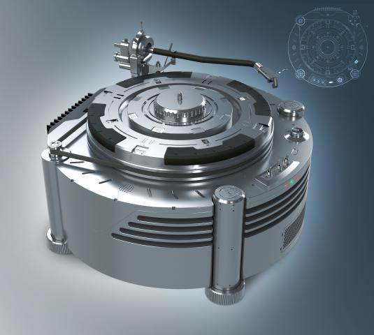
I must point out that MoI doesn't do photo-realistic images at all and it's not advertised anywhere that I know of for designing decorative objects, although you could do that if you wanted to. MoI is perfectly capable of creating an accurate model of anything from a vase to a jet engine, but not in a parametric way. This is why it can export in SAT, IGES and STEP formats, etc. The v5 beta that I'm running also uses the ACIS modeling kernel as well as Solids++. I'm fairly sure that the need to use surfaces will creep up on you as your designs change. Martin. Have you read the MOI blurb, or looked at the Gallery Martin? MOI say, my bold: 'Focused on being easy to use, it's a great tool for designers and artists who want to construct accurate models.' Designers and artists rather than engineers. Examples:
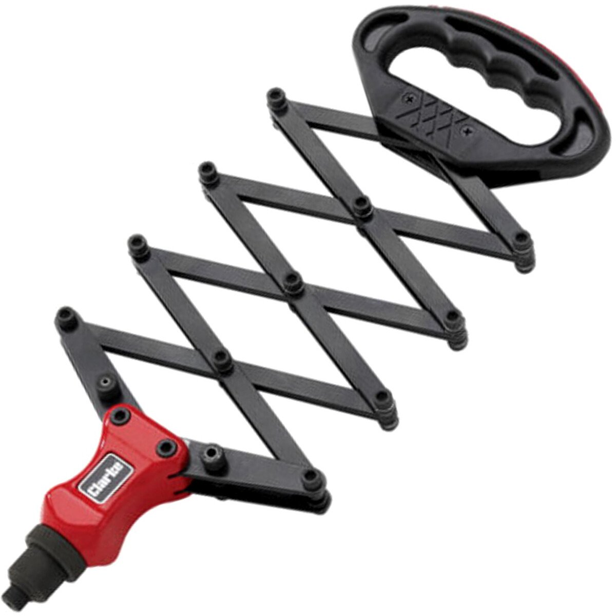
The last MOI example represents a record turntable. It's a broadly correct and scaled external view that could be 3D printed as a model, used to illustrate a forum post, or published in a glossy magazine advert. Great, so far as it goes, but tell me if I'm wrong: the turntable isn't an engineering model. It's an outer view of a turntable with nothing inside. Alibre, SE, and Fusion are different. They get outer appearance almost as a side-effect of modelling all the internal parts. This type of CAD models engineering assemblies, where each part, maybe thousands of them, are designed sufficient to make or source a real one. There would be a motor, drive train, arm-linkages, and all the other fixtures and fittings necessary to make a real turntable, positioned inside the outer casing. The model will often include trivia like washers, bearings, o-rings, fuse-holders, and cable clips etc. so the overall weight is always known, and a full BOM available. This type of CAD modelling is much more focussed on getting the engineering detail right than look, which is added later. The model of the arm assembly would be accurate enough to confirm that the counter-weight correctly balanced the cartridge, and also to swing across the record with the necessary geometry. After that the shiny good looks depicted by MOI are paint, putty and polish. MOI focusses on selling, whilst parametric CAD focusses on manufacture. Both are important. The MOI turntable model has many features designed to make it look top-quality hi-tech, but which are unlikely to be functional. MOI is top-notch for that, hi-fi fanboys would buy that turntable I'm sure. My sort of CAD model focuses on the practical, where the MOI's sexy rear 'heat-sink' is implemented as some chrome-plated plastic fins stuck on the back, whilst the engineering design uses intelligently sized standard items clipped on the transistors. MOI doesn't need to model the heat capacity of heatsinks, modelling for production does. There's a lot of overlap between the two approaches, but MOI punches hard at the artistic end, whilst Alibre and friends concentrate on engineering. In the middle both tools produce similar results, but I don't think MOI can model a jet engine as an assembly. How about a working lazy tong?
Dave
|
| JasonB | 19/05/2023 16:16:41 |
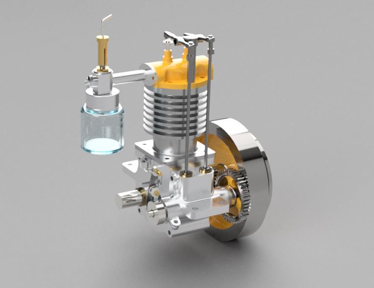
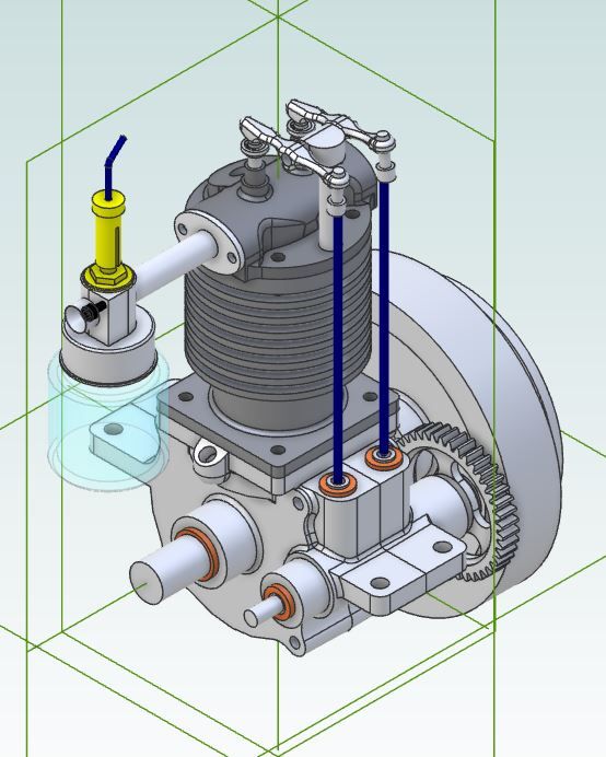
25215 forum posts 3105 photos 1 articles | Dave, how do you know there is nothing inside that record player? I really just depends on what you want to design, some may be happy with a barstock engine that looks just like it was made from barstock, others may want it to look like it was made from castings others designs may be very organic I'd call myself a model engineer not a model artist and would find the options in MOI quite useful when trying to replicate old or new cast parts If you pay for the render option with alibre that record player is no problem to get the same look, I'm tight and would use F360 to do the renderings I've only set the glass jam jar fuel tank as transparent but all the workings are inside the shiny outer layer
Also worth looking at the MOI model of that turntable, when you break it down it is far more of an "engineering" job made up of basic geometric shapes that could just as easily be done in Alibre, Fusion, etc The rendering of the turntable was not actually done in MOI
Edited By JasonB on 19/05/2023 16:34:07 |
| Peter Cook 6 | 19/05/2023 16:34:48 |
| 462 forum posts 113 photos | As Jason says there is no problem modelling parts and assembling them in MOI, but which tool you choose depends both on what you want to do, AND which ones you find easiest. I use MOI simply because I "get on" with its underlying design paradigm. Never having ben trained in engineering design or technical drawing I struggle to get my head around the paradigm that underlies the majority of the 3D CAD programs. This is an MOI model of a clock I plan to make. All the parts can be separated from the whole, and drawings or diagrams created to take across t the workshop. Drawing each part in MOI makes me think about the design choices, while putting them together in MOI makes sure that they fit together.
One approach is not better than the other - they are just different, and at the limits are capable of different things. I will never reach the limits, so I stay in the middle with the tools that I find easiest to use. |
| blowlamp | 19/05/2023 16:41:25 |
1885 forum posts 111 photos | Dave. Remember that these are just renders of the solid models produced by MoI. I'm not trying to claim MoI is anything more than it actually is. You wouldn't design the Space Shuttle in it, just as you wouldn't try to do that in Fusion 360 or Alibre products. What I am able to do in MoI is produce both solid model files, STL and DXF files, along with dimensioned drawings for my own use. I can send its output to my CAM systems and create excellent gcode for my CNC lathe & milling machine.
"The last MOI example represents a record turntable. It's a broadly correct and scaled external view that could be 3D printed as a model, used to illustrate a forum post, or published in a glossy magazine advert. Great, so far as it goes, but tell me if I'm wrong: the turntable isn't an engineering model. It's an outer view of a turntable with nothing inside."
You are almost certainly wrong: As I didn't model the turntable myself I can't tell you how well it has been constructed, but I can tell you that if I had modeled it, then each part of it would be to correct size and ready for transfer to Solid Edge, Fusion 360, Alibre or any CAM system. The Cars you have posted do give a good indication of some of the nice shapes you can make in MoI that would be manufacturable directly from the MoI file output. The models I make in MoI can be imported into your favourite mechanical CAD app and edited there - they are just the same NURBS models.
Martin.
|
| SillyOldDuffer | 19/05/2023 16:41:34 |
| 10668 forum posts 2415 photos | Posted by Peter Cook 6 on 19/05/2023 16:34:48:
As Jason says there is no problem modelling parts and assembling them in MOI, but which tool you choose depends both on what you want to do, AND which ones you find easiest. I use MOI simply because I "get on" with its underlying design paradigm. Never having ben trained in engineering design or technical drawing I struggle to get my head around the paradigm that underlies the majority of the 3D CAD programs. This is an MOI model of a clock I plan to make. All the parts can be separated from the whole, and drawings or diagrams created to take across t the workshop. Drawing each part in MOI makes me think about the design choices, while putting them together in MOI makes sure that they fit together.
One approach is not better than the other - they are just different, and at the limits are capable of different things. I will never reach the limits, so I stay in the middle with the tools that I find easiest to use. Looks like I have to retreat in confusion: I couldn't find anything on MOI's website suggesting it can do Assemblies, and yet here's Peter's clock. Must have missed it. Does the clock model animate? Oh dear, sackcloth and ashes, I shall have to buy Martin a pint... Dave |
| JasonB | 19/05/2023 16:47:49 |
25215 forum posts 3105 photos 1 articles | As we are talking about renderings here are a couple of images, one of a model New Holland hit & Miss engine, the rights of which were bought by Littlelocos but the patterns were missing so he had to recreate them from the existing inventory that he bought as well as bringing them upto a standard that buyers expect these days not what they were like 30 odd years ago. If Nigel is following the work to reproduce the main casting was done in Turbocad and allowance has been added for double shrinkage so metal masters can be made, machining allowances etc. It will be cast in a gun metal type metal. This is a good example where compound curves, blending of parts etc is all part of the engieering process
Bit more on their FB page Edited By JasonB on 19/05/2023 16:48:51 |
| Peter Cook 6 | 19/05/2023 16:55:59 |
| 462 forum posts 113 photos | Posted by SillyOldDuffer on 19/05/2023 16:41:34:
Looks like I have to retreat in confusion: I couldn't find anything on MOI's website suggesting it can do Assemblies, and yet here's Peter's clock. Must have missed it. Does the clock model animate? Oh dear, sackcloth and ashes, I shall have to buy Martin a pint... As I don't use the other CAD systems, for the reasons explained above, I am not 100% sure what you mean by "doing assemblies". That model is put together part by part - in almost exactly the way I would do it in the workshop. Each part is created individually (in my case mostly by hiding the rest of the model while I do so), then connecting or associated parts are unhidden using the browser and the bits put together, then the rest of the model is unhidden. That model was actually created by designing the three trains as separate MOI models, then combining them into a single one. It doesn't do animations, although I often use stepwise rotation of parts to ensure things don't interfere with each other. |
| lee webster | 19/05/2023 17:24:43 |
| 383 forum posts 71 photos | I am still plodding on with MOI, I won't give up just yet! I drew an engine cylinder with water jacket. Now I want to create a water inlet on the side of the jacket. I drew a rectangle 3mm away from the surface.
And then tried to extrude it up to the surface with 5 degrees of draft.
I couldn't find a way of doing that except to run the extrusion past the cylinder face and boolean union the two parts. On virtually all other cad programmes I've used, a simple extrude would have done the job. Am I missing something? Or does MOI use boolean for all add/subtract operations? Also, I couldn't find a "project to surface" function, it would have made drawing the initial outline of the water inlet a bit easier. Still early days. |
| Peter Cook 6 | 19/05/2023 17:51:08 |
| 462 forum posts 113 photos | Posted by lee webster on 19/05/2023 17:24:43:
Also, I couldn't find a "project to surface" function, it would have made drawing the initial outline of the water inlet a bit easier. I think the function you want is in Construct/Curve which has four choices Project - Isect- Silhou - ISO Although have never used them, they seem to do what you want. I do use Boolean for most add/subtract operations - but then I am still learning. One other thing to be aware of, there are available ( for free via the forum) a lot of add-in functions that can be used in MOI. I use the one that creates threaded fasteners, and one that creates gear wheels (specify Mod & Tooth count). There are many others.
Edited By Peter Cook 6 on 19/05/2023 17:52:08 |
| SillyOldDuffer | 19/05/2023 20:10:37 |
| 10668 forum posts 2415 photos | Posted by Peter Cook 6 on 19/05/2023 16:55:59:
Posted by SillyOldDuffer on 19/05/2023 16:41:34:
Looks like I have to retreat in confusion: I couldn't find anything on MOI's website suggesting it can do Assemblies, and yet here's Peter's clock. Must have missed it. Does the clock model animate? Oh dear, sackcloth and ashes, I shall have to buy Martin a pint... As I don't use the other CAD systems, for the reasons explained above, I am not 100% sure what you mean by "doing assemblies". That model is put together part by part - in almost exactly the way I would do it in the workshop. Each part is created individually (in my case mostly by hiding the rest of the model while I do so), then connecting or associated parts are unhidden using the browser and the bits put together, then the rest of the model is unhidden. That model was actually created by designing the three trains as separate MOI models, then combining them into a single one. It doesn't do animations, although I often use stepwise rotation of parts to ensure things don't interfere with each other. My retreat may have been premature, because that's not what I mean by an Assembly. I'd call it a group, that is a selection of bodies, each drawn individually, positioned adjacent to each other. In FreeCad the parts are identified in a tree from which they can be hidden or reworked. They are only related by their position in space. Here's an example of what SE means by an Assembly, Fusion is similar. It's a rough start at a Lazy Tong Riveter:
It's an assembly of 4 parts: a Brass "handle", an Aluminium pin, which runs in the slot, and an arm, 6-off. The arms are connected by 7 rotating joints, plus 1 rotating joint at a hole in the handle, and a non-rotating joint to the Aluminium pin, which has a tangent joint with the slot. As shown in the next mage, I've extended the arms by sliding the pin up the slot. Moving the pin operates moves all the other joints. This is the same model, except the joints have operated, Pulling the pin down moves all the joints and retracts the tong:
Note the pin hasn't travelked the full length of the slot because an arm has collided with a corner on the handle. Joints are modelled too, allowing the Assembly to move realistically, and can detect when distant parts hit each other, as a result of the movement of 'n' joints away. All the parts can be used by other assemblies, and this assembly (with joints), could be assembled within another assembly, also with joints. If I change the original arm part, all the arms used in the assembly change. If the change breaks a joint, the assembly won't animate until the joint or other relationship is fixed. The model supports step-wise refinement, divide and conquer, and part re-use. As parts and sub-assemblies are independent, projects can be developed by teams, not just singleton developers. Next step in this riveter is to connect the far arms to a hinged cam that pulls a shaft and clutch that grips the pop rivet, all inside some sort of head. Then I'd add fasteners to join the tong arms together, and either drill and thread the cam to the pull shaft (two parts), or tap the shaft for a bolt (three parts). Both methods can be tried, because many cam and shaft variations can be modelled independently, and - provided they fit - can be swapped around. This is important in production : might be cheaper to bolt, because that removes one threading operation, or could be more convenient to thread the shaft. Or maybe the whole thing should be cast, drop-forged, or force fitted. Having looked again at the MOI website, I don't believe it does this type of Assembly. But I accept what MOI does is effective too. Dave
Edited By SillyOldDuffer on 19/05/2023 20:12:51 |
| blowlamp | 20/05/2023 00:34:01 |
1885 forum posts 111 photos | A video with a few ways to get things properly positioned in MoI, for things like stud or bolt holes and also attaching a boss to the side of a cylinder.
Martin.
|
| lee webster | 20/05/2023 08:39:42 |
| 383 forum posts 71 photos | Thanks for the video Martin. Believe it or not, that's what I ended up doing. The one thing that isn't obvious from my pics is that I had already created the water jacket inside the block. The dotted lines are barely visible. It was wondering how to do the boolean operation between extrusion and block without leaving a piece imbedded in the jacket that slowed me down. But MOI took care of that itself. The hole I then created in the face of the extrusion caused some concern because I wanted it to stop somewhere in the jacket and not take a chunk out of the cylinder wall. I did it, but it mainly guess work. I can see a more accurate way to do it, but I haven't tried yet. I will have another go later. I will also get some images of the cylinder head from Designspark that I want to draw in MOI. Not the sidevalve head on the engine I posted earlier, this one is an OHV with sparkplug and a water jacket. I will use the finished head to also produce the pattern and moulds for casting one. This is all an excercise! |
| blowlamp | 20/05/2023 11:55:09 |
1885 forum posts 111 photos | Lee. Glad you haven't given up. Sorry if you are already aware of this, but you can load images of the head for tracing purposes etc, if that helps. Also, If you get stuck whilst using a particular tool the ?Help icon takes you straight to the information about the tool in use. I find it sometimes gives me a useful nudge.
Martin. |
| lee webster | 20/05/2023 21:30:38 |
| 383 forum posts 71 photos | I have drawn a simple water cooled OHV cylinder head in MOI. I can't say it was easy, MOI has it's own way of doing things that I'm not used to. The only thing I didn't do is the water inlet. It would have been easy to add it, but all this is only practise. This pic is a general view of the head. All lines are hidden and the head is coloured grey-ish.
This is a cut-away view showing inlet tract, water passage and spark plug hole.
Next I have removed the top of the head to show the water passage and other internals.
It's early days yet, 87 days of a 90 day trial to go. I will still look at other packages, including, and I never thought I would say this, monthly or yearly subscription. I could get the latest copy of Designspark Mechanical for a tenner a month that would have all the tools I need, for the price of a mobile phone contract. I will also check out Solidworks student or hobbiest cad package. I think that's about £100 per year. |
| JasonB | 21/05/2023 07:04:51 |
25215 forum posts 3105 photos 1 articles | Looks good, now all you need to do if perfect that casting technique! Have you had any more attempts at that? |
| lee webster | 21/05/2023 08:11:20 |
| 383 forum posts 71 photos | Hi Jason. No time for casting at the moment, all my spare time is spent building the model cars I am making. I hope to start painting them in primer soon. Before I try casting again I want to make new elements for my electric foundry. I will aim for 2.5kw to get up to temp quicker. I am also going to order some oil bound sand to try. As for MOI, it isn't for me. I have seen what others have done using it, but it isn't like using a dedicated cad programme. The head above took far too many steps to create than with any other cad programme I've used. And thats not because I am new to the programme. I will stick with Designspark and Solid Edge, unless something better comes along. |
| lee webster | 22/05/2023 20:09:43 |
| 383 forum posts 71 photos | Strewth! Talk about back-tracking. I have now re-installed MOI, after 100% believing it wasn't for me. When I put a "lid" on the cylinder head (see above) to create the top, I thought everything was going well. I was wrong. For some reason, when I boolean joined the top to the main body, it also filled in the water jacket with a solid. I discovered this when I tried slicing the head to have a look inside. I deleted the water jacket solid, and there was another one under that. I deleted that and was left with a solid head, no water jacket at all. I restored the two water jackets and named the head. I then hid the head, deleted the first water jacket solid, and named the second one. I made the head visible again and boolean cut the jacket from the head which created a void where it should be. I then uninstalled MOI and started to look for another cad package to try, I even looked at Turbocad, which looks really good on paper. That was yesterday. Today I started to think about MOI again. I don't know if I did something wrong, or if MOI has a certain way of working. Anyway, I reinstalled MOI and tried a new approach. So far, it seems to be working, and I have to admit, for such a tiny programme, it packs in a lot of features. I didn't know the Text feature was so good, and the help file is really good. I did think that I wouldn't want to spend £260 buying MOI, but now....... I have 85 days left of the trial to make up my mind. |


Please login to post a reply.
Magazine Locator
Want the latest issue of Model Engineer or Model Engineers' Workshop? Use our magazine locator links to find your nearest stockist!
Sign up to our Newsletter
Sign up to our newsletter and get a free digital issue.
You can unsubscribe at anytime. View our privacy policy at www.mortons.co.uk/privacy
Latest Forum Posts
- *Oct 2023: FORUM MIGRATION TIMELINE*
05/10/2023 07:57:11 - Making ER11 collet chuck
05/10/2023 07:56:24 - What did you do today? 2023
05/10/2023 07:25:01 - Orrery
05/10/2023 06:00:41 - Wera hand-tools
05/10/2023 05:47:07 - New member
05/10/2023 04:40:11 - Problems with external pot on at1 vfd
05/10/2023 00:06:32 - Drain plug
04/10/2023 23:36:17 - digi phase converter for 10 machines.....
04/10/2023 23:13:48 - Winter Storage Of Locomotives
04/10/2023 21:02:11 - More Latest Posts...
- View All Topics
Support Our Partners


Shopping Partners
Subscription Offer

Latest "For Sale" Ads
- Reeves** - Rebuilt Royal Scot by Martin Evans
by John Broughton
£300.00 - BRITANNIA 5" GAUGE James Perrier
by Jon Seabright 1
£2,500.00 - Drill Grinder - for restoration
by Nigel Graham 2
£0.00 - WARCO WM18 MILLING MACHINE
by Alex Chudley
£1,200.00 - MYFORD SUPER 7 LATHE
by Alex Chudley
£2,000.00 - More "For Sale" Ads...
Latest "Wanted" Ads
- D1-3 backplate
by Michael Horley
Price Not Specified - fixed steady for a Colchester bantam mark1 800
by George Jervis
Price Not Specified - lbsc pansy
by JACK SIDEBOTHAM
Price Not Specified - Pratt Burnerd multifit chuck key.
by Tim Riome
Price Not Specified - BANDSAW BLADE WELDER
by HUGH
Price Not Specified - More "Wanted" Ads...
Get In Touch!
Do you want to contact the Model Engineer and Model Engineers' Workshop team?
You can contact us by phone, mail or email about the magazines including becoming a contributor, submitting reader's letters or making queries about articles. You can also get in touch about this website, advertising or other general issues.
Click THIS LINK for full contact details.
For subscription issues please see THIS LINK.
Digital Back Issues


Donate

 Register
 Log-in
Model Engineer Magazine
- Percival Marshall
- M.E. History
- LittleLEC
- M.E. Clock

ME Workshop
- An Adcock
- & Shipley
- Horizontal
- Mill

Subscribe Now
- Great savings
- Delivered to your door

Pre-order your copy!
- Delivered to your doorstep!
- Free UK delivery!
All Forum Topics > CAD - Technical drawing & design > MOI cad. It looks good, is it?