Forum sponsored by:

Unimat 3 Restoration
| Graham Meek | 03/11/2021 21:05:34 |
| 714 forum posts 414 photos | Hi John and Jason, That is a very kind offer which I might have to take you up on. The man at Emco, Austria, did say he would have to go down to the basement and dig out the original drawings. As these are not on the current computer system in PDF format. If he cannot find them I will get back to you. Of what I remember from my Unimat days the belt drive shaft to the gearbox is at a slight angle. As regards the spindle change, I currently want to keep it standard. I have an ESX 25 collet attachment on the Compact 5 which suits my needs. I do need to make the Tommy bars for the 3-jawed chuck as these were not in the box, so if anyone to tell me the standard length of these I would be grateful. Regards Gray, |
| John Olsen | 04/11/2021 05:12:52 |
| 1294 forum posts 108 photos 1 articles | The standard tommy bars are 60mm long by 4mm diameter. So far as I can tell, the material is a bit better than mild steel, they can be bent with over enthusiastic use but normally are OK. I would suggest though that you look through the old magazines, I had an article published about twenty or so years back about making C spanners to suit the Unimat. These are not hard to make, although the one for body of the three jaw does need an awkward cutout to clear the jaws. and they do end up making things a lot easier. There is one to suit the pulley end of the spindle, two for the three jaw, two for the collett chuck, and one to fit the milling attachment spindle. I made a lever actuated tailstock for mine too, ver useful. I don't think the belt drive to the fine feed is at any sort of angle, I looked at mine just now and it all looks square. The body of the attachment is a funny shape but when it is on the machine the pulley shaft looks to be parallel to the base and square to the spindle. I've got a mini rotary table made out of one of those. Of course that belt is only an O ring, but it works OK. John
|
| JasonB | 04/11/2021 07:02:19 |
 25215 forum posts 3105 photos 1 articles | The groove on the input to the fine feed is forward of the spindle ctr line so in that respect it the belt is at an angle. The side of the belt running down to the feed is fairly parallel to the back of the head but the returning side is quite angled due to the spindle groove being a lot nearer the head than the ctr line of the input shaft, this does help feed the belt though. Also twisted through 90 deg as the input shaft runs front to back. Edited By JasonB on 04/11/2021 07:21:57 |
| Graham Meek | 05/11/2021 17:50:44 |
| 714 forum posts 414 photos | Hi John, and Jason, Please excuse my tardy reply, the past two days have been a bit hectic. Thanks for the info on the Tommy bars and the additional clarity on the Power feed attachment. I was convinced it was on a slight angle, that is my memory for you. It is interesting that you made a rotary table out of the drive. Many years ago I made a dividing head using the same items. With its 40:1 ratio it was ideal, I may still have the original paper drawing of the main body. I will try and look it out. Today I finished grinding the new Spindle and Tailstock barrel. The manufacture of which has been a bit of a trial in that the M14x1 gauge I made years ago left my threads oversize and I had to pick-up each thread and re-screw cut to size. The Moral here is to use the 3 wire system first, not last. The gauge is now in the scrap bin. Hopefully I will have some more photographs over the next few days. Regards Gray, |
| Graham Meek | 07/11/2021 13:45:18 |
| 714 forum posts 414 photos | With the Sun shining into the workshop I was able to take a couple of photographs
The shot above shows the old and new parts together prior to fitting onto the lathe.
Now it is beginning to look more like a lathe. The drawing in the foreground is the project for this week. When received the lathe came with a GEC 1/8 HP Induction motor, which was full of Brass swarf. The motor weighs more than the lathe and the original Motor mounting plate had been severely chopped about. While the motor fitted in its allotted place the overhanging weight attached to the Headstock was not considered a good idea. Hence the new DC drive is more compact, less weight and is more powerful. Regards Gray,
|
| Graham Meek | 14/11/2021 16:17:33 |
| 714 forum posts 414 photos |
This last week saw the pair of new backplates finished. The new spindles for the idler pulleys were finished this morning after the photo-shoot. I did have some good fortune midweek in that the missing Power feed housing turned up. My lathe donor had finished cleaning out his shed and came across this part. The euphoria was short lived however when I discovered one of the previous owners had taken a twist drill to the Wormwheel bore. Why they had done this is beyond me and it is probably the reason why I had all the other parts. The hole left after the drilling was anything but round, and off centre. Luckily there was about 6 mm of the original 8 mm bore remaining. This allowed me to clock this to get onto the original centre. The hole was then bored out to 9.5 mm and a Phos Bronze bush made to salvage the unit.
Lastly the cover in-situ to make sure everything fits as it should. This week I hope to get a start made on the mounting board and the Motor pulleys. Regards Gray, |
| Graham Meek | 04/12/2021 19:18:14 |
| 714 forum posts 414 photos | Progress on the restoration has slowed over recent weeks. Mainly due to the effects of my booster jab on my illness. Father Christmas did get his dates mixed up however in that I had an early Christmas present from my Daughter in the form of the Milling attachment for the the Unimat.
You will see from the above Photograph that the lathe is now sporting some new Handwheels, which have been made in-house with adjustable dials.
I wanted to keep the Black Handwheel theme going, so the main part of the handwheel was made from Delrin. The small piece of Silicone O-ring acts as a spring to provide friction on the dial by displacing the Delrin ear on the handwheel.
The ear can be seen more clearly in this shot, as well as where the small piece of silicone goes.
This shows the dial in-situ on the longitudinal feed, or leadscrew.
Originally I made one new Idler pulley for the Milling attachment and two motor pulleys, but yesterday I noticed the original plastic mandrel pulley was running out by a mile. When received this lathe was fitted with some vacuum cleaner drive belts. These had been on the machine for sometime while in storage and had given the pulley a permanent set. A new aluminium pulley was duly made.
The original integral catches on each guard had been broken at some stage. A piece of Delrin was machined to fit the vacant space and four small magnets were pressed in to keep the guard closed in use.
I tried to mimic the original catch as best I could. The small protrusion makes getting the guard open very easy. The replacement piece is held in lace by two small self tapping screws. My next task is to make the base board to house the electrics for the motors. Regards Gray, Edited By Graham Meek on 04/12/2021 19:20:57 Edited By Graham Meek on 04/12/2021 19:21:58 |
| Graham Meek | 05/12/2021 11:16:12 |
| 714 forum posts 414 photos | This view shows the two self tapping screws and the shape of the Delrin filler piece better. Note the two shadow lines to simulate the original catch.
(Clicking on the image makes things clearer) Regards Gray, |
| Graham Meek | 10/04/2022 17:03:03 |
| 714 forum posts 414 photos | Following a period of post-Op recovery I have at long last been able to take some photographs of what has been happening in the workshop.
Apart from a coat or two of varnish on the woodwork this project is complete. I am very pleased with the outcome. The machine is much quieter than I remember the Unimat to be with its AC Motor. There is an added bonus in that the lathe toolholders for my Compact 5 will fit directly into the topslide toolpost without any alteration to centre height. Regards Gray, Edited By Graham Meek on 10/04/2022 17:03:53 |
| Howard Lewis | 11/04/2022 16:28:07 |
| 7227 forum posts 21 photos | Good Work! And a machine which is very useable, and of which you can be proud. If it were me, I would be continually gazing at it, just for the pleasure! Howard |
| Graham Meek | 11/04/2022 20:48:02 |
| 714 forum posts 414 photos | Thanks for the kind comments Howard, I have been putting the lathe to use today on some bearings for my Compact 5 screwcutting clutch. I am really pleased with the smoothness and quietness of this machine. It has been well worth the effort, plus I saved it from the skip Regards Gray, |
| KEITH BEAUMONT | 20/07/2022 09:42:46 |
| 213 forum posts 54 photos | Graham, I have sent you a PM. Keith |
| Graham Meek | 20/07/2022 10:49:16 |
| 714 forum posts 414 photos | Hi Keith, I am sending you an email about the parts I used. Regards Gray, Edited By Graham Meek on 20/07/2022 10:49:31 |
| Nigel Graham 2 | 20/07/2022 10:57:12 |
| 3293 forum posts 112 photos | Excellent work. Have you sent photos of the finished item and its cabinet to Emco? I think they'd very happy to see it given a new lease of life.
I hope it inspires me to achieve something towards that quality when I come to restore my always-loved but well-worn EW lathe. That presently has a modern motor, but still like its predecessor, a 230V AC one. Your comments about treating your Emco to D.C. drive makes me think that route for my machine. |
| Graham Meek | 20/07/2022 17:15:17 |
| 714 forum posts 414 photos | Thanks Nigel, Alas Emco have moved on from the Hobby machines, having amalgamated with a much larger concern. They are more industrially based these days. This to me is a pity as they gave the Hobby many innovations over the years, which have been copied around the world. I have been using the U3 today to put the finishing touches to my Proxxon Milling machine table feed attachment. Regards Gray,
|
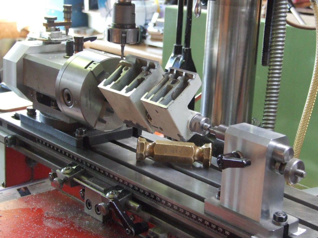
| Graham Meek | 07/05/2023 16:44:43 |
| 714 forum posts 414 photos |
I have had several PM's over recent months for details on the above modification. I have written up some notes for anyone else who is considering this salvage scheme. "This repair is not an easy task and it needs to be approached methodically. The only safe surfaces to come off are the cross-slide flat ways. As the Lug portion the leadscrew passes through is tapered on all four sides. Using parallels the cross-slide faces are bolted to a small angle plate. By using a couple of dowels about 5 mm diameter in the dovetail vee the carriage assembly is clocked parallel to the edge of the angle plate. The dovetail ways of the cross-slide now being vertical to the surface plate and the bottom "working face" of the angle plate. (Lug needs to be uppermost) In a vertical type mill bolt the angle plate to the machine table. With a close fitting "turned spigot" in the existing leadscrew tapped hole and using an edge finder locate the leadscrew centre-line, parallel to the angle-plate vertical face. Once on this centre-line and using a Verdict type clock. Clock either side of the casting Lug to bring the leadscrew lug central under the machine spindle. From memory the thickness of the casting at this point is 15 mm. A 10 mm drilled, bored and reamed hole is then machined in the casting. Re-clamping the angle-plate such that the leadscrew centre-line is now running vertically. Using the turned spigot again, clock to get the leadscrew and spindle centre-lines concentric. Open up the existing tapped hole using an 8 mm end mill, followed by an 8.1 or 8.2 mm drill. Nothing bigger as there is not much meat about here. It is best to rough out the PB nut, tap the 8 mm LH thread and then finish machine the outside diameter to size, (9.99 mm for a reamed hole). Tapping PB throws up awful burrs and distortion on the diameter, hence why I used this method. It goes without saying that the tapped hole has to be on the centre-line of the 10 mm diameter, so some careful machining is required on this part" I hope these notes help. Regards Gray. Edited By Graham Meek on 07/05/2023 16:49:02 |


Please login to post a reply.
Magazine Locator
Want the latest issue of Model Engineer or Model Engineers' Workshop? Use our magazine locator links to find your nearest stockist!
Sign up to our Newsletter
Sign up to our newsletter and get a free digital issue.
You can unsubscribe at anytime. View our privacy policy at www.mortons.co.uk/privacy
Latest Forum Posts
- *Oct 2023: FORUM MIGRATION TIMELINE*
05/10/2023 07:57:11 - Making ER11 collet chuck
05/10/2023 07:56:24 - What did you do today? 2023
05/10/2023 07:25:01 - Orrery
05/10/2023 06:00:41 - Wera hand-tools
05/10/2023 05:47:07 - New member
05/10/2023 04:40:11 - Problems with external pot on at1 vfd
05/10/2023 00:06:32 - Drain plug
04/10/2023 23:36:17 - digi phase converter for 10 machines.....
04/10/2023 23:13:48 - Winter Storage Of Locomotives
04/10/2023 21:02:11 - More Latest Posts...
- View All Topics
Support Our Partners


Shopping Partners
Subscription Offer

Latest "For Sale" Ads
- Reeves** - Rebuilt Royal Scot by Martin Evans
by John Broughton
£300.00 - BRITANNIA 5" GAUGE James Perrier
by Jon Seabright 1
£2,500.00 - Drill Grinder - for restoration
by Nigel Graham 2
£0.00 - WARCO WM18 MILLING MACHINE
by Alex Chudley
£1,200.00 - MYFORD SUPER 7 LATHE
by Alex Chudley
£2,000.00 - More "For Sale" Ads...
Latest "Wanted" Ads
- D1-3 backplate
by Michael Horley
Price Not Specified - fixed steady for a Colchester bantam mark1 800
by George Jervis
Price Not Specified - lbsc pansy
by JACK SIDEBOTHAM
Price Not Specified - Pratt Burnerd multifit chuck key.
by Tim Riome
Price Not Specified - BANDSAW BLADE WELDER
by HUGH
Price Not Specified - More "Wanted" Ads...
Get In Touch!
Do you want to contact the Model Engineer and Model Engineers' Workshop team?
You can contact us by phone, mail or email about the magazines including becoming a contributor, submitting reader's letters or making queries about articles. You can also get in touch about this website, advertising or other general issues.
Click THIS LINK for full contact details.
For subscription issues please see THIS LINK.
Digital Back Issues


Donate

 Register
 Log-in
Model Engineer Magazine
- Percival Marshall
- M.E. History
- LittleLEC
- M.E. Clock

ME Workshop
- An Adcock
- & Shipley
- Horizontal
- Mill

Subscribe Now
- Great savings
- Delivered to your door

Pre-order your copy!
- Delivered to your doorstep!
- Free UK delivery!
All Forum Topics > Manual machine tools > Unimat 3 Restoration