Forum sponsored by:

Turning (approximating) a Domed Surface
| Howard Lewis | 28/09/2021 11:33:54 |
| 7227 forum posts 21 photos | 50 mm radius on a 25 mm bar sounds like a job for a radius turning tool Either a special just for this job or ma more sophisticated one for other, later, jobs. At a pinch, maybe a boring head mounted on the toolpost, so that it can rotate about its axis, might suffice. (Making a tool, to make a tool, to do a job! ) More ways of skinning a cat, (Not that I am suggesting making a tool for skinning cats. mFirst objection would mbe from ours! ) Howard |
| JasonB | 28/09/2021 12:12:18 |
 25215 forum posts 3105 photos 1 articles | It's not on the end of a 25mm bar, look at the images posted. Being quite a thin item if held in a chuck most ball turning tools will foul the chuck |
| Howard Lewis | 28/09/2021 13:25:32 |
| 7227 forum posts 21 photos | Misread the bit about 25 mm diameter. Approaching the problem from another point, make up a concave form tool, run slow and feed very gently along the lathe axis? If you really fancy your chances grind from a 1/2" HSS toolbit! Put some gauge plate, off set in the 4 jaw and carefully turn a concave to make the form tool. Harden / temper as you see fit. Having no clearance the tool would need to be mounted at angle to provide a clearance angle.. For brass, with care, and only one or two to make, you might even get away as is. Howard |
| Dr_GMJN | 28/09/2021 14:20:42 |
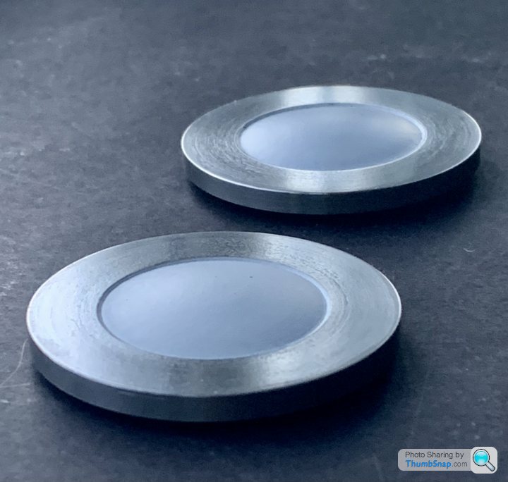
 1602 forum posts | I didn't buy castings for these end caps, I got some cast iron bar, and will make them from that. I'm going to go for an arc, not an ellipse, because I think the apex looks more defined like that (rather than a bit flat if I use an ellipse). I'm also going to make the apex of the dome project about 1 mm from the bolt face rather than having it flush (as per instructions), again to make the form a bit more defined. If it looks wrong I'll just try again with different settings. |
| JasonB | 28/09/2021 14:28:50 |
25215 forum posts 3105 photos 1 articles | If it's of use this is the profile I drew for the Victoria, radius and protruding
|
| Dr_GMJN | 28/09/2021 22:11:25 |
1602 forum posts |
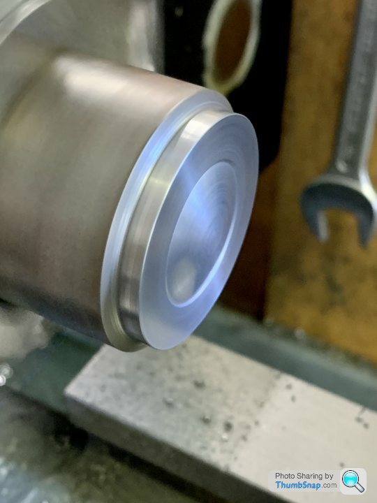
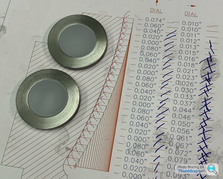
Thanks Jason, I drew something out on CAD earlier, I think it will be OK. Just have to work out the co-ordinates. I think 25 increments of 0.020” on the cross slide should be good, using a 0.8 tip radius tool. Might need back-gear for this one:
|
| JasonB | 29/09/2021 07:07:43 |
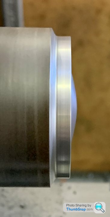
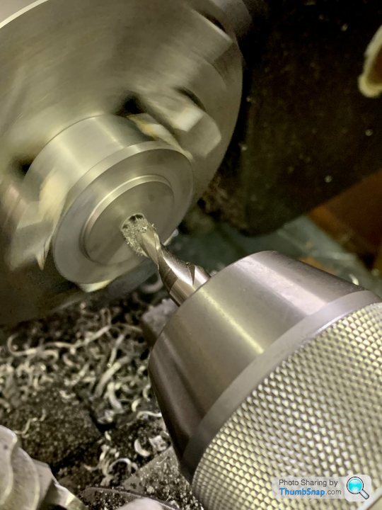
25215 forum posts 3105 photos 1 articles | The 2.6mm will be OK and still likely to be more than the valve chest cover with it's recessed surface Make sure your DCMT insert won't rub it's edge to start with. You will probably have to start from the outside and work inwards as the tool will rub on the smaller diameters if working outwards. I'd be inclined to rotate the toolpost further so that the edge of the tip nearest you is parallel of just beyond the axis of the lathe, you can then hold something against the edge of the cover and touch the tip against that as you wind the cross slide towards you and as the OD is known you can move 7.5mm in to the first cut Edited By JasonB on 29/09/2021 07:35:29 |
| Dr_GMJN | 29/09/2021 13:26:16 |
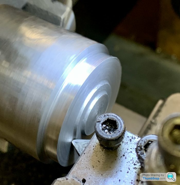
1602 forum posts | Thanks Jason. I might turn the tip as you say, and might even draw out a starting geometry that I can rough machine out, to make sure the edges don’t rub. I guess you can see where the cutting edges end by looking carefully at the tip? |
| JasonB | 29/09/2021 15:03:52 |
25215 forum posts 3105 photos 1 articles | Looks like you may just have enough clearance
|
| Dr_GMJN | 29/09/2021 17:01:21 |
1602 forum posts | Ah, I misunderstood - tool rubbing on its flank, on the ‘I/d’ of the step? Do DCMT inserts have a standard flank angle (to stop rubbing) that you’ve modelled? Thanks. |
| JasonB | 29/09/2021 17:28:47 |
25215 forum posts 3105 photos 1 articles | Yes, the C in dCmt signifies the angle which is 7degrees and by far the most common though others are available. This is why you see the insert boring bars tilting the insert at an angle so the side does not rub in a small bore. |
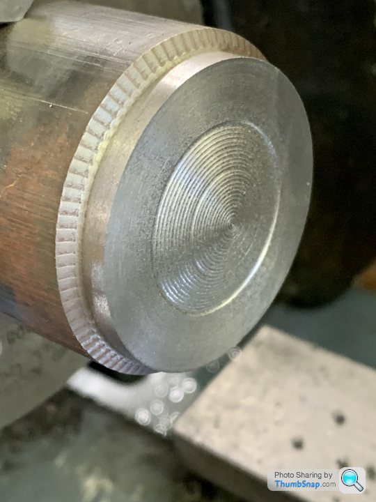
| Dr_GMJN | 04/10/2021 22:17:49 |
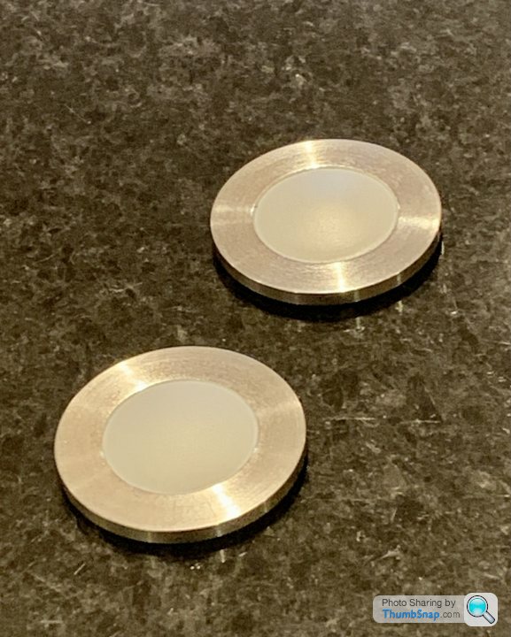
1602 forum posts | Just to wrap the thread up, I used the co-ordinate method. I used the side of the insert touched on the side of the blank cap, and the tip touched on the PCD face to get datums for everything: Thanks everyone for the advice. Job done with your help - again. Edited By Dr_GMJN on 04/10/2021 22:20:01 |


Please login to post a reply.
Magazine Locator
Want the latest issue of Model Engineer or Model Engineers' Workshop? Use our magazine locator links to find your nearest stockist!
Sign up to our Newsletter
Sign up to our newsletter and get a free digital issue.
You can unsubscribe at anytime. View our privacy policy at www.mortons.co.uk/privacy
Latest Forum Posts
- hemingway ball turner
04/07/2025 14:40:26 - *Oct 2023: FORUM MIGRATION TIMELINE*
05/10/2023 07:57:11 - Making ER11 collet chuck
05/10/2023 07:56:24 - What did you do today? 2023
05/10/2023 07:25:01 - Orrery
05/10/2023 06:00:41 - Wera hand-tools
05/10/2023 05:47:07 - New member
05/10/2023 04:40:11 - Problems with external pot on at1 vfd
05/10/2023 00:06:32 - Drain plug
04/10/2023 23:36:17 - digi phase converter for 10 machines.....
04/10/2023 23:13:48 - More Latest Posts...
- View All Topics
Support Our Partners


Shopping Partners
Subscription Offer

Latest "For Sale" Ads
- Reeves** - Rebuilt Royal Scot by Martin Evans
by John Broughton
£300.00 - BRITANNIA 5" GAUGE James Perrier
by Jon Seabright 1
£2,500.00 - Drill Grinder - for restoration
by Nigel Graham 2
£0.00 - WARCO WM18 MILLING MACHINE
by Alex Chudley
£1,200.00 - MYFORD SUPER 7 LATHE
by Alex Chudley
£2,000.00 - More "For Sale" Ads...
Latest "Wanted" Ads
- D1-3 backplate
by Michael Horley
Price Not Specified - fixed steady for a Colchester bantam mark1 800
by George Jervis
Price Not Specified - lbsc pansy
by JACK SIDEBOTHAM
Price Not Specified - Pratt Burnerd multifit chuck key.
by Tim Riome
Price Not Specified - BANDSAW BLADE WELDER
by HUGH
Price Not Specified - More "Wanted" Ads...
Get In Touch!
Do you want to contact the Model Engineer and Model Engineers' Workshop team?
You can contact us by phone, mail or email about the magazines including becoming a contributor, submitting reader's letters or making queries about articles. You can also get in touch about this website, advertising or other general issues.
Click THIS LINK for full contact details.
For subscription issues please see THIS LINK.
Digital Back Issues


Donate

 Register
 Log-in
Model Engineer Magazine
- Percival Marshall
- M.E. History
- LittleLEC
- M.E. Clock

ME Workshop
- An Adcock
- & Shipley
- Horizontal
- Mill

Subscribe Now
- Great savings
- Delivered to your door

Pre-order your copy!
- Delivered to your doorstep!
- Free UK delivery!
All Forum Topics > Workshop Techniques > Turning (approximating) a Domed Surface