Forum sponsored by:

Boxford STS Screwcutting Clutch
| Graham Meek | 16/02/2021 11:19:50 |
| 714 forum posts 414 photos | Hi Matt, No problem, I know other things in life are taking a priority at the moment. Regards Gray,
In my post vaccination stupor yesterday I knew I would forget one clutch. The Warco BH 600. This was another collaboration, and this was completed by Graham Howe. Graham's help was vital in making the Myford ML 7 version. I also should have added the Atlas and Craftsman lathes are one in the same. This version was done following a request from Walla Walla, Washington State, USA. Hopefully my collaborator there will write that version up in HSM as soon as he has finished it. Regards Gray, |
| Trevor Steele | 17/02/2021 13:58:47 |
| 6 forum posts 4 photos | Thank you all for you kind words on my work. The bulk of the praise should go to Gray, as without his excellent design work this would never have materialized. In use I have found there is a small issue with the accuracy of the end stop. Due to the long operating arm this is not as accurate as I would like. I have done some tests and am currently modifying the design to address this. I hope to have this completed in the next week or so and will send updated drawings to Gray as well as some more pictures.. Best regards Trevor |
| Graham Meek | 18/02/2021 16:32:27 |
| 714 forum posts 414 photos | Hello Trevor, Welcome to the Forum, I thank you for your kind words but I could not have designed this version without your input. For my part the designing was the easy bit, your part was much harder. I have the last few of your photographs I selected to post. The first is a view of the internals of the Clutch Housing
The next shows one of the Dog Gears in-situ
With a separate view of the Dog Gear, showing the Drive Dog, and Trevor's use of DU lined bushes for the bearing bush.
This next photograph shows the two Idler gears and their shafts, again using DU lined bushes and note the oil holes in the shafts which connect with Oilers in the end of the shafts.
Lastly we have the Splined Output shaft to match the Boxford Change gears.
The Oilers for the idler gears can be seen in this photograph. The Oiler on the top of the housing will lubricate the Dog Gears etc. Being in a housing there will after time be an oil bath for these gears in the bottom of the housings. Regards Gray, Edited By Graham Meek on 18/02/2021 16:35:55 |
| Pete. | 18/02/2021 17:08:27 |
 910 forum posts 303 photos | Thank you both for more information on this, I look forward to hearing Trevor iron out the kinks and have it working to his satisfaction. |
| Oldiron | 18/02/2021 17:58:13 |
| 1193 forum posts 59 photos | I would be very interested in the drawings for the SB/Boxford AUD clutch. Are they available any where ? regards |
| Graham Meek | 19/02/2021 14:48:19 |
| 714 forum posts 414 photos | Posted by Oldiron on 18/02/2021 17:58:13:
I would be very interested in the drawings for the SB/Boxford AUD clutch. Are they available any where ? regards
About the time as I was designing this particular clutch, I had enquires about the Boxford AUD. Volunteers came forward, but I think the work involved frightened them away. As requests for further information went un-answered. In the interim, due to the similarities between the South Bend and the Boxford lathes I have always pointed prospective Boxford builders to the South Bend Post I made on the Model Engine Maker some years ago. As I have never had anyone come back to say the South Bend version has been completed, I cannot give any guarantees. However based on my past record I think it is a good one. Maybe here is a chance for you to adapt the design to the Boxford and be the first. As I said in the opening paragraph of this post I have deleted any drawings I made, which now seems a pity due to the rekindled interest. Regards Gray,
|
| Oldiron | 19/02/2021 15:46:03 |
| 1193 forum posts 59 photos | Thanks for that Gray. I need to dig out my MEM pw & see if I can find the article. regards |
| Graham Meek | 19/02/2021 17:25:09 |
| 714 forum posts 414 photos | Posted by Oldiron on 19/02/2021 15:46:03:
Thanks for that Gray. I need to dig out my MEM pw & see if I can find the article. regards A Google search for "South Bend Screwcutting clutch Graham Meek" took me straight there. Regards Gray, |
| Oldiron | 19/02/2021 18:20:17 |
| 1193 forum posts 59 photos | Thaks for the link Gray. I had a quick look but will need to study it further when I get a spare half hour. regards |
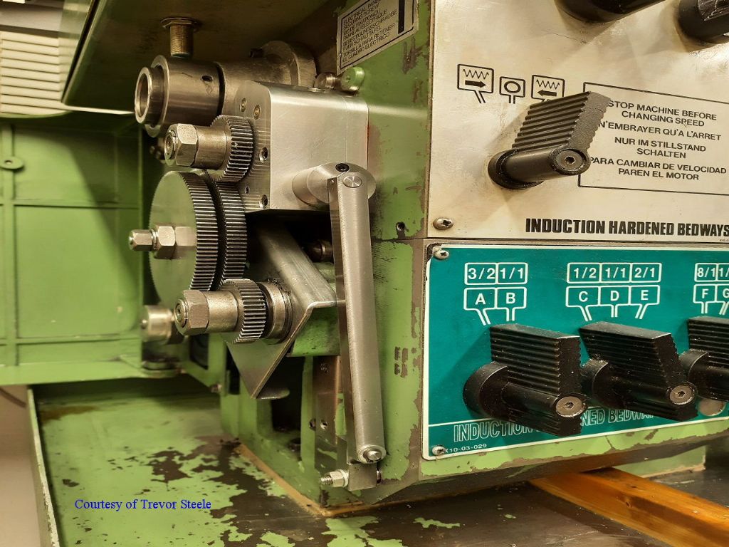
| Trevor Steele | 22/02/2021 19:15:40 |
| 6 forum posts 4 photos | Just to let everyone know how I have been getting on with the tests on the Boxford clutch. I replaced the long operating arm with a shorter one to help improve the sensitivity of the end stop as can be seen in the photo. The final result was a bit inconclusive. The original system was a bit insensitive due to the long operating arm, while the modified design has a bit more 'spring' in the system due to the long extension to reach the shorter arm. In the end I believe either setup will work. I will stick with this latest version to see how it works out in practice.
|
| Pete. | 23/02/2021 01:34:10 |
910 forum posts 303 photos | Thanks for the update, I'd be interested to know how you get on with this in practice when you've had a chance to use it. Are there drawings available for the STS Boxford? |
| James G 1 | 23/02/2021 09:03:32 |
| 10 forum posts 1 photos | Just to say that I am also following this with interest and would be interested in drawings if available. Is there any advantage in having matching slight tapers on the engaging surfaces of the dog clutch i.e. on the drive dog and the semi-circular end of the recess with which it engages ? The taper would be such as to have the dog more narrow at it's end than at it's base, such that there would be a slight tendency (depending on taper angle) for the clutch to disengage unless held by a detent. The only dog clutch I have had a chance to examine was a multi-tooth clutch in the feed gearbox of a toolroom type mill and this had a very definite taper on the dog faces, hence my enquiry. J. |
| Clive Foster | 23/02/2021 10:02:31 |
| 3630 forum posts 128 photos | James Taper on the dogs won't work. Basically you are starting off with it half worn out. Multi tooth dog clutches are different. Taper is basically there so the things will engage without needing excessive backlash for clearance. A single tooth clutch doesn't have the engagement issues beacue it inherently has most of a circles worth of backlash. Taper form wear is a known failure issue in the P&W Model B system. Basically leads to the clutch not staying engaged at higher speeds and higher cutting loads. Which isn't good because not only does the single tooth clutch drive pretty much everything except the spindle on the B the machine itself is capable of removing metal at a very serious rate putting high loads on the dogs. Mine is OK but not in perfect health. Taper also leads to inconsistent release position as the actual release drag loads vary more with change in cutting load. Ideally the drag on the dogs as the clutch triggers out of engagement should be independent of drive load. The P&W system uses short, stiff actuation levers and hefty spring loads for very positive actuation. Its also deep inside the headstock where it receives continuous lubrication so its operating under best possible conditions. Being external Grahams (excellent) design will, relatively speaking, suffer more from dog drag variation because you cannot arrange continuous lubrication. The longer levers inevitably mean more spring in the system which reduces the sharpness of the disengage. Flip side is that Grahams system is engineered for lighter machines so loads will be lighter and its not so fundamental to machine operation as it is on my P&W where the third rod control operates the dog clutch so it gets used for everything. Ideally you'd briefly pause the drive as the clutch actuates so the drive train briefly overruns the spindle by a fraction of a degree minimising drag at the point of shift. Which is impractical without serious electronics. Grahams design is what it is and works well. Trying to guild the lily leads you straight down a rabbit hole of needless difficulties which, in the real world, make little if any difference. Might be interesting to see the effect of a serious anti friction coating on the dogs would be, eg DLC, but I'm betting you'd hardly notice. About the only realistic way to improve on Grahams concept is to use an externally powered actuator, motorcycle quick shifter perhaps, and operate it electronically by picking off a control feed from a DRO system. Unfortunately nobody makes a DRO with a suitable control output. Which is a pity because using a trigger at zero output in conjunction with the offset memories, mine has 99 of the things, would make a very flexible bed stop system. Clive |
| Trevor Steele | 23/02/2021 10:35:10 |
| 6 forum posts 4 photos | Pete, There are drawings for the Boxford clutch available, although they may require further explanation for some of the parts. I'm happy to supply these to anyone who is interested. If you PM me your details I will email you a copy. They are in AutoCAD format. Trevor |
| James G 1 | 23/02/2021 13:51:32 |
| 10 forum posts 1 photos | Hi Clive, Thanks for your comprehensive reply - it's amazing how subtle can be the details of a simple mechanism. Certainly as you say consistent lubrication should help - the latest version as discusssed on this thread is enclosed and may effectively have it's own oil bath. Hopefully I'll be able to build it and enjoy the luxury of using it. Thanks again, J.
|
| Graham Meek | 23/02/2021 17:09:21 |
| 714 forum posts 414 photos | Hi Clive, Thanks for picking up the gauntlet and explaining the flaws in the tapered clutch teeth, and thanks for the kind words. Being an Analogue Guy in a Digital World I tend to steer clear of the Electronics. Barring metal failure, mechanical solutions tend to go on for ever. (There is no software to get out of date), Gray, Generally, Any adaptation to a machine tool is going to beset with compromises. Usually one compromise leads to another and the desired goals or features of the adaptation start to fall below the initial design standard. It is a totally different thing to design a machine from scratch which has a screwcutting clutch incorporated in the basic design. Trip rods and pivot points can be placed where they are best suited mechanically. Sometimes, like with my Emco Maximat clutch. My initial design was to be fitted inside the headstock, but for other reasons I had to make a compromise and fit the clutch externally as here with the Boxford. This in itself led to there being more gears in set-up than I would have liked. Which means the noise level has gone up slightly, but as I am going deaf it does no bother me that much. Thus we have 2 compromises in this design, 3 if you count the external mounting. Initially repeatability straight after fitting this clutch was not as good as I had hoped for, but after using the clutch for sometime now the trip points are predictable, and there is no variation. The point here is, things need time to bed in and the sharp edges to round over a little. Regards Gray,
Edited By Graham Meek on 23/02/2021 17:09:49 |
| Tony Ray | 04/03/2021 08:02:35 |
| 238 forum posts 47 photos | Hi Graham’s & Trevor, As previous poster commented the STS solution may well be a good start for other machines which have the tumbler reverse in the headstock. I have a Harrison M250. At first glance it looks like the challenge on the STS I was to get the unit in the space between the headstock casting and the first gear in the external train so as to maintain the alignment of this gear with the next one located on the banjo. On the M250 that first gear is commonly changed to obtain two ranges for screw cutting in my case 22 & 44T being metric. I must admit even with Grays book I struggled a bit to understand where this all fits until I read Clive’s helpful explanation which is worth repeating here: “Screwcutting clutches are single tooth dog clutches running at spindle speed, located before the screwcutting drive gear train, operated by a fast operating knock out trip” I will contact Trevor to ask for the CAD files as Inthinknthey will be a good starting point for the M250. Tony
|
| Graham Meek | 04/03/2021 11:53:58 |
| 714 forum posts 414 photos | Hi Tony, Clive's statement does generally hold true, but there is, "the exception that proves the rule". I know in one instance, and it may well be the STS above. There was an internal reduction with-in the headstock of 3:1. In other words the output shaft where the clutch is fitted is running at 1/3 spindle speed. Conversations at the time were stating that the clutch would not work. At first glance this would seem to be the case, however the single dog will only engage at one point in this reduction train each time, because the gears inside the headstock have remained in mesh throughout. Please keep us informed of your progress and if you get stuck we are only an email away. (A photograph of the space available might not go amiss). Regards Gray,
|
| Trevor Steele | 04/03/2021 12:37:25 |
| 6 forum posts 4 photos | Hi Tony, Gray is correct in saying that the STS drive to the gearbox is 1/3 of the spindle speed. So long as the ration between spindle and gearbox is a whole number of turns, the dog clutch will work. If the ratio was for example 1:2.5 then it would not. The disadvantage of a slower gearbox speed is that engagement of the clutch may be a bit slower as it only comes around every 3 revolutions of the spindle in the case of the STS. In practice is is not really noticeable. The advantage is that it is kinder on the dog clutch as the speed of the clutch is lower, which reduces the impact on the drive dog. Best regards Trevor |
| Tony Ray | 04/03/2021 21:43:54 |
| 238 forum posts 47 photos | Hi Trevor & Graham, Thanks for your replies. Firstly I can confirm that the output shaft on the M250 rotates exactly at the same rate as the spindle. Looking at the output shaft side on there is a boss approx 10mm deep that is bolted to the main casting, This supports a 38mm spigot on which the banjo hangs. All in all there is 40mm between the back face of the driven gear and the main casting which is a flat face. This space is occupied by the 10mm thick boss 14mm thick banjo and various spacers. There is a good image of the drive set up on Lathes.co.uk I will try to post some images in a few days. |


Please login to post a reply.
Magazine Locator
Want the latest issue of Model Engineer or Model Engineers' Workshop? Use our magazine locator links to find your nearest stockist!
Sign up to our Newsletter
Sign up to our newsletter and get a free digital issue.
You can unsubscribe at anytime. View our privacy policy at www.mortons.co.uk/privacy
Latest Forum Posts
- hemingway ball turner
04/07/2025 14:40:26 - *Oct 2023: FORUM MIGRATION TIMELINE*
05/10/2023 07:57:11 - Making ER11 collet chuck
05/10/2023 07:56:24 - What did you do today? 2023
05/10/2023 07:25:01 - Orrery
05/10/2023 06:00:41 - Wera hand-tools
05/10/2023 05:47:07 - New member
05/10/2023 04:40:11 - Problems with external pot on at1 vfd
05/10/2023 00:06:32 - Drain plug
04/10/2023 23:36:17 - digi phase converter for 10 machines.....
04/10/2023 23:13:48 - More Latest Posts...
- View All Topics
Support Our Partners


Shopping Partners
Subscription Offer

Latest "For Sale" Ads
- Reeves** - Rebuilt Royal Scot by Martin Evans
by John Broughton
£300.00 - BRITANNIA 5" GAUGE James Perrier
by Jon Seabright 1
£2,500.00 - Drill Grinder - for restoration
by Nigel Graham 2
£0.00 - WARCO WM18 MILLING MACHINE
by Alex Chudley
£1,200.00 - MYFORD SUPER 7 LATHE
by Alex Chudley
£2,000.00 - More "For Sale" Ads...
Latest "Wanted" Ads
- D1-3 backplate
by Michael Horley
Price Not Specified - fixed steady for a Colchester bantam mark1 800
by George Jervis
Price Not Specified - lbsc pansy
by JACK SIDEBOTHAM
Price Not Specified - Pratt Burnerd multifit chuck key.
by Tim Riome
Price Not Specified - BANDSAW BLADE WELDER
by HUGH
Price Not Specified - More "Wanted" Ads...
Get In Touch!
Do you want to contact the Model Engineer and Model Engineers' Workshop team?
You can contact us by phone, mail or email about the magazines including becoming a contributor, submitting reader's letters or making queries about articles. You can also get in touch about this website, advertising or other general issues.
Click THIS LINK for full contact details.
For subscription issues please see THIS LINK.
Digital Back Issues


Donate

 Register
 Log-in
Model Engineer Magazine
- Percival Marshall
- M.E. History
- LittleLEC
- M.E. Clock

ME Workshop
- An Adcock
- & Shipley
- Horizontal
- Mill

Subscribe Now
- Great savings
- Delivered to your door

Pre-order your copy!
- Delivered to your doorstep!
- Free UK delivery!
All Forum Topics > Manual machine tools > Boxford STS Screwcutting Clutch