Forum sponsored by:

Alternative valve mechanism
Comments sought on simple valve mechanism idea.
| Brian G | 16/02/2021 14:45:16 |
| 912 forum posts 40 photos | Hi John It might be worth drawing your valve gear at different positions of the crank and comparing the valve openings to the Dockstader simulations. Several of them use an oscillating lever similar to yours, but derive their action from the vertical movement of the crank which is automatically 90 degrees out of phase with the piston. Brian G |
| John Bramwell | 16/02/2021 16:24:01 |
| 24 forum posts 6 photos | Brian et al Didnt have much luck with Dockstader but found J,Y Jins computor simulations (https://www.youtube.com/watch?v=ed3vMFQNzCc) Timing realtionship between valve sheet and main piston of a steam. And his cylinder is the same as mine so this supports Redsitters advice. Please have a look at this and tell me what you think. I still think my design will run because the steam will push the piston in the right directiion which is the absolute basics. And if i build it and it doesnt work then it is not too hard to change it to put a crank in the wheel axle at 90 deg to drive an adjustable eccentric. |
| David Caunt | 16/02/2021 20:09:22 |
 110 forum posts 40 photos | John, Your diagram shows the piston in a position where the inlet is fully open when the con-rod is horizontal. Your wheel should be rotated already past the horizontal before the valve opens otherwise it would try to stop the rotation. That's is where the timing comes in. Dave |
| John Bramwell | 18/02/2021 10:34:17 |
| 24 forum posts 6 photos |
|
| John Bramwell | 18/02/2021 10:43:42 |
| 24 forum posts 6 photos | Gentlemen Ive replaced that silly pendulum with z timing wheel driven by the flywheel This does 4 things 1. Puts horozontal movement in line with valve chamber, 2 reduces main piston stroke length to valve stroke length. 3 phases the timing to open a TDC. 4 Alows for future fine tuning of timing. I didnt copy the Caladonian becausd i like needle rollers over slots and eccentrics. Your comments please and many thanks for previos help. |
| Redsetter | 18/02/2021 11:04:25 |
| 239 forum posts 1 photos | John, Is your loco going to have one cylinder, or two, or more, and where on the loco are they to be mounted? Also does it need to be reversible? All this affects the choice of valve gear. Ease of manufacture also comes into it - what are the smallest parts you are prepared to handle, and especially, what are the smallest holes you are prepared to drill? Looking at your diagram, the timing wheel will certainly create the 90 degree phase difference - BUT - I do not see any provision for adjustment - in practice it won't need to be exactly 90 degrees - and with a single link driving the timing wheel, surely it will only rotate 180 degrees before it jams or reverses?. I can see some good ideas there, but it is all getting more complicated than a normal slip eccentric gear, which is easy to make, and is all you really need in a simple 0 gauge model.
Edited By Redsetter on 18/02/2021 11:22:09 |
| John Bramwell | 18/02/2021 12:32:09 |
| 24 forum posts 6 photos | Thanks Redsetter for you promt comments. You may not have been able to read the note under the timing wheel "crank sits 10mm out from wheel"That allows the driving arm to go under the the crank and not hit it. The pivot for the valve arm is above the crank. Another clarification the crank is one piece with the drive pin.to keep the valve arm pivot concentric The "future'' fine tuning I refered to consists an outer disc which can rotate wrt the back disc. The front disc would be screwed to the back through slots. Bit like the Bosch VE injection pump on my car. But ill redo it with an eccentric and see how it looks The driving arm would go over the top of it. Stay tuned for revision.. |
| John Bramwell | 19/02/2021 08:08:04 |
| 24 forum posts 6 photos | Dave, you mean lime this? See revised plan. John |
| SillyOldDuffer | 19/02/2021 16:12:39 |
| 10668 forum posts 2415 photos | Looking at:
struck me that moving the upper wheel and crank on to the main axle turns this into a Stephenson Gear, which in plain form is mechanically a bit simpler. Stewart Harts PottyMill shows the principle. Although the eccentric on his engine isn't mounted on the flywheel, it could be. And the eccentric could be replaced by a crank, making it even closer to John's suggestion. (The advantage of the eccentric over a fixed crank is it can be moved to fine tune the phase.)
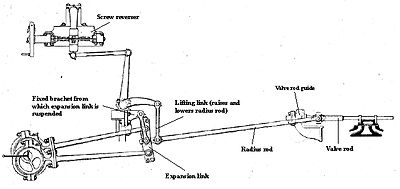
The Stephenson gear fitted to locomotives is basically the same thing except the linkage is considerably complicated by allowing the driver to select both forward and reverse with variable lead. This is the early Gooch variation: most of the complexity is due to having two eccentrics and the screw-reverser, but with them removed isn't it similar?
Dave |
| Nigel Graham 2 | 20/02/2021 00:48:48 |
| 3293 forum posts 112 photos | To amplify David Caunt's point, the valves should be just on the point of opening to admission as the crank passes through dead-centre. Large engines are made with a very small early opening called "lead" , but this a very carefully-calculated value, and not applicable in an application like this. For reference I think the sorts of gear Brian G cites, with the vertical drive, are Hackworth and its Marshall and Bremme derivatives. They drive the end of the radius-rod in an ellipse whose horizontal component (not axis) gives the valve travel, and whose major axis angle sets the direction. Hackworth is common on small narrow-gauge locos, but needs quite a bit of headroom; and despite its apparent simplicity, like most valve-gears it requires careful setting-out. Stephenson's Gear always has two eccentrics- one for each direction, essentially. That Gooch variant, and the Allan Straight-Link equivalent, differ only in adding links and joints, and fell by the track-side while the slightly simpler Stephenson's became so widespread on locos and traction-engines.. John - Your " This does 4 things 1. Puts horizontal movement in line with valve chamber, 2 reduces main piston stroke length to valve stroke length. " 1) Good idea. 2) With respect I am puzzled by that. The valve travel is usually less than the (power) piston stroke. For a simple engine with no lead, the maximum valve-travel V = 2(lap + port opening) in full gear. In Gauge 0 it's usual to be in either full or mid-gear anyway, no "notching up". and in mid-gear, V = 2.lap I.e the ports do not actually open, though the valve-gear moves them just enough to be on the edge. By port opening I mean the maximum port opening to admit steam to the cylinder, and depending on design is not necessarily the port width. The valve closes at the cut-off set by your design, but I would think it no later than around 75%. On the exhaust stroke the port is open to exhaust for virtually the whole of the piston-stroke, so the valve has no exhaust lap to speak of. ' Looking at your drawing, the valve appears to have no admission lap. I could not enlarge it sufficiently to read the text without losing it in pixels, but I think I am right you are using inside-admission, as usual with piston-valves, so the valve is about to move right-wards. It shows both piston-valve heads line-on-line with both edges of their ports; so no lap. That will give a cut-off of 100%, so return very poor running for a lot of steam. The two bobbins should be lengthened on their inner (inlet steam) sides, meaning at the engine's position shown the valve should be further to the right by that lap, not in its mid-travel as you've drawn. It would require the ports and bobbins both moving closer together to accommodate the extra travel in the same valve-chest. (On locomotives the valve-chest is usually longer than the cylinder, but this to accommodate long-travel valves and direct steam-passages for fast running with heavy loads.) ' I did write that lot aware you may already know some of it, but I hope it helps, and look forwards in due course to photos of the results. |
| John Bramwell | 21/02/2021 11:57:43 |
| 24 forum posts 6 photos | Nigel. many thanks, i would go with the potmill but except that i want the valve chamber above the main chamber to save space so i can have this on bothsides of the loco. Ive got O gauge track. I said that my timing wheel 2 reduces the main piston stroke length to valve stroke length You say "'2) With respect I am puzzled by that. The valve travel is usually less than the (power) piston stroke. But if you look at the drawing, the valve arm pivot is closer to the centre than the driving pivot so there is no puzzel. main piston stroke 19mm valve 10mm. the crank piece is above the driving arm pivot and the valve arm piivot is on top of the crank piece. What is a good bore and stroke for an O gauge loco on flat track? Do slide valve leak less than piston valves made to the same tolerances? It might help if i give you the loco layout as im sure there will be more trap for young players. Cheers John |
| Nigel Graham 2 | 21/02/2021 13:49:09 |
| 3293 forum posts 112 photos | I was giving the basic principle of reciprocating steam-engine valve design, not the valve-gear design. I am not questioning how you intend to drive the valve. By all means experiment with valve-gear designs of your own though you'd be hard-pressed to re-invent something established in many different forms over 100 years ago. You proposed an inside-admission piston-valve engine. That is a well-proven approach, standard for most larger railway locomotives and some road steam vehicles. ' The only novel part was your proposed valve-gear - as I say, experiment but you would be hard-pushed to develop a "new improved" valve-gear nowadays. Many manufacturers of full-size engines tried over maybe 150 years, and between them invented no more than perhaps a dozen or so basic valve-gears and variants on them; and with time settled on just the few best ones. ' Your drawing shows no lap - a recipe for failure I am afraid. I explained that. However it was too small and faint to read its annotations, even when enlarged, but the text implied piston-stroke < valve-travel - that is what puzzled me, not your valve-gear design. The piston stroke and diameter are the primary dimensions for any given engine, and you match the valve and its gear to them, not vice-versa as the words seemed to imply. By the way, the valve works in the "valve-chest" and the piston in the "cylinder", not "chambers". ' As for appropriate bore and stroke for O-gauge, that varies considerably and depends rather on whether you are modelling a prototype (so about scale sizes) or free-lance. However, as a guide, Martin Evans' book Model Steam Locomotive Construction gives: Bore: 3/8 Stroke: 9/16 - 5/8 Steam ports: 1/16 x 3/16 Exhaust port: 1/8 x 3/16 All in inches... and I think he was writing about 2-cylinder, slide-valved models of Standard Gauge locos; but certainly well time before the modern "Garden Gauge" models based more often on Narrow-Gauge practice, became popular. (I am using the appropriate entries in his table to help me design my steam-wagon engine.) A slide-valve is inherently less prone to leaking because the live-steam pressure in on its outside, pressing it onto the valve-face. To allow this, it is made to float slightly and only perpendicularly on its connection with the valve-rod, without end-to-end shake. This of course assumes the mating faces are properly flat and smooth to start with. It does mean the valve-rod gland has to seal against full live-steam pressure, without gripping the valve-rod too tightly, but it is perfectly possible as many Gauge 0 locos and similarly-sized static engines are built in that way. Piston-valves do demand very precise making, lapped fits and very careful attention to sealing to minimise leaking past without absorbing too much power in friction. You also need consider how if fitted with sealing-rings or packing those will travel over the port-edges without catching on the edges - the usual way is to form the port not as a slot but as a ring of circular or triangular holes in a sleeve called a "liner"; but then the design starts to become complicated and the building more difficult. In Gauge 0 with its low loads, you might get away with simple piston-valves lapped to fit in directly-bored valve-chests, but any leaking due to wear could be corrected only by re-machining both parts. Their main advantage lies in the valve-rod gland being faced only with the very low exhaust pressure. ' By all means show us more drawings but please consider how they might appear on the wide variety of screens we have between us, viewed by the Eyeball Mk 1 that comes in many varieties of sensitivity and age! |
| John Bramwell | 22/02/2021 16:33:38 |
| 24 forum posts 6 photos |
|
| Redsetter | 22/02/2021 17:59:38 |
| 239 forum posts 1 photos | John, I think you should study some existing simple 0 gauge designs. For example - LBSC's "Bat" and "Mollyette," and Dave Watkins's "Wild Rose," and "Brick." - four different types of loco, all with different mechanical layouts. |
| Nigel Graham 2 | 22/02/2021 21:07:52 |
| 3293 forum posts 112 photos | John, I agree with Redsetter - examine other designs for ideas and general design practices. Yes- that slide valve is drawn as it should be, with the "lap" at each end, but needs moving to the left a touch with the piston in that position. Referring to your drawing, that is so it is starting to open the right-hand port to steam just as the crank is passing dead-centre, while its inside edge is opening the left-hand port to exhaust. The gear driving it is arranged to do that, at both dead-centres, by its action being about 120º ahead of the crank. The actual angle depends on the proportions of the particular engine's valve and ports. ' Note that the slide-valve needs to be able to "float" vertically but without end-play, so the steam will hold it down onto the port-face. I'm not sure what the usual practice in this scale is, but I can see how to do it on your arrangement if you've not already done so Slot the lug through which the valve-rod passes, vertically, so the valve can move up and down on the rod a touch. Then either thread the rod back to near the end of the valve, and place a pair of lock-nuts with turned washers each side of the lug. Or - and perhaps better as well as simpler - you can arrange the lug to be between a pair of simple collars held with grub-screws to the rod. In either case these fittings are adjusted so the valve can find its own level, but without end-float. This allows the valve to seal down on the port-face, and for you to adjust the valve's position along its rod to put the timing spot-on. I know you've not shown the details, but the joint between the valve-rod and its link needs a guide like a small crosshead of its own, to keep the valve-rod running straight and true. Just a simple collar with a lug that holds the joint itself, running on a rod projecting from the valve-chest. ' Combining the two in one lump of metal... Many locos are built that way, and it gives the cylinder a dual role as a frame-stretcher. Do though ensure it will be reasonably easy to remove and replace the valve-chest covers, for setting and servicing the valves. Some full-size locos, usually small tank locomotives but also the GWR main-line classes, were built with their cylinders outside the frames but the valve-chests and valve-gear inside, for looks. They can't have been easy to service in full-size, and miniature versions are in some ways worse because our full-size hands don't fit the scale-size spaces available! (I'm told there is no truth in the tale that their former designers went on to teach car-designers...) |
| duncan webster | 22/02/2021 23:52:45 |
| 5307 forum posts 83 photos | You've got the dimension across the frames at 33mm. The distance twixt the rails in gauge ) is 31.75mm, something amiss? I can't read the drawing very well, but if there is meant to be one coupling rod connecting the axle to the shaft carrying the eccentrics (layshaft) it ain't going to work, you'd need 2. It's all getting a bit complicated, and you won't be able to have suspension on that axle (do O gauge locos have suspension?). I have a loco not too dissimilar, but the layshaft is driven by a chain and gears from the axle. Why? just to annoy a fellow club member who was too far up himself! The layshaft goes the opposite rotation to the axle, but it works a treat A nice simple way of driving outside valves is to have slip eccentrics on the axe with a rocking shaft, see drawings of Tich amongst many others |
| John Bramwell | 23/02/2021 12:50:58 |
| 24 forum posts 6 photos | Hello Duncan Yes 33 was an error. But on that, should the wheel sit square on the track with a the flange on the inside? Could you explain why i need two shafts from the axle to the layshaft? is that to put the two engines ot of phase? Love your chain driven layshaft and i can imagine the reaction to it. I had a 1970 BMW SOHC with a cam drive chain and oil pressure tenioner. No changing belts. Did you make the sprokets? My goal is not to build a mini version of an actual loco or to design an engine that is different for the sake of it, but to design an engine that is simple and easy to make to entain the kids. john
|
| John Bramwell | 23/02/2021 12:59:05 |
| 24 forum posts 6 photos | Nigel. The LBSC Juliet might be good for me, It has the main cylinder on the outside of one continuous frame member and the valves on the inside. I can fit my cylinders on the inside and valves on the outside for ease of access but the cranks and arms underneath might make fitting the burners tricky. |
| Nigel Graham 2 | 23/02/2021 14:00:05 |
| 3293 forum posts 112 photos | You could do that, yes, but as you say you do need work out very carefully where everything will fit around everything else because you'd need make the rear axle the driving one, and that as a crankshaft. LBSC designed another small engine, the 'Tich' which had the cylinders and valves both outside the frames, with the valve chest vertically above the cylinder. He gave it Baker or Walschaerts valve-gear but I think you could arrange yours - the Bramwell Gear - for it. In fact your gear looks as if it would suit such an "over-and-under" layout very well. Doing that leaves the space above the axles and between the frames nearly empty (many miniature locos have a boiler feed-pump in there, driven by an eccentric on the axle). It also avoids having to make a crank-axle. The neatest way to drive your valve-gear with that all-outside arrangement would be a return-crank on the outer end of the driving crank-pin, which is extended to suit, as used on Walschaerts Gear. |
| duncan webster | 23/02/2021 19:14:39 |
| 5307 forum posts 83 photos | Posted by John Bramwell on 23/02/2021 12:50:58:
Hello Duncan Yes 33 was an error. But on that, should the wheel sit square on the track with a the flange on the inside? Could you explain why i need two shafts from the axle to the layshaft? is that to put the two engines ot of phase? Love your chain driven layshaft and i can imagine the reaction to it. I had a 1970 BMW SOHC with a cam drive chain and oil pressure tenioner. No changing belts. Did you make the sprokets? My goal is not to build a mini version of an actual loco or to design an engine that is different for the sake of it, but to design an engine that is simple and easy to make to entain the kids. john
Imagine a 4 coupled loco, but take one of the coupling rods off. Have the cranks at 12 oclock. Now rotate 1 wheel clockwise to 3 oclock. The other will follow clockwise. Now rotate the first wheel a bit more, the driven wheel doesn't know which way to turn. You need a second set of rods/crankpins at 90 degrees to the first lot. Actually it can be other than 90, three cylinder engines are at 120 degrees. You'd now need what are effectively 2 identical crank axles, and they are things to avoid as a beginner. Even if you do have 2 crank axles, you cant have suspension because as the axle rises and falls it will try to lift the layshaft. Definitely the easiest is slip eccentric between the frames with rocking levers to get the drive from inside to valves outside above the cylinders. If you pm me your email address I'll send you some drawings. I wouldn't go for a Tich, the bits are very small, and they are not easy to drive, fire is so small it goes out as soon as you blink. Juliet is nicer, don't know whether he had a slip eccentric version, but would be easy enough to cook up Edited By duncan webster on 23/02/2021 19:16:00 |


Please login to post a reply.
Magazine Locator
Want the latest issue of Model Engineer or Model Engineers' Workshop? Use our magazine locator links to find your nearest stockist!
Sign up to our Newsletter
Sign up to our newsletter and get a free digital issue.
You can unsubscribe at anytime. View our privacy policy at www.mortons.co.uk/privacy
Latest Forum Posts
- hemingway ball turner
04/07/2025 14:40:26 - *Oct 2023: FORUM MIGRATION TIMELINE*
05/10/2023 07:57:11 - Making ER11 collet chuck
05/10/2023 07:56:24 - What did you do today? 2023
05/10/2023 07:25:01 - Orrery
05/10/2023 06:00:41 - Wera hand-tools
05/10/2023 05:47:07 - New member
05/10/2023 04:40:11 - Problems with external pot on at1 vfd
05/10/2023 00:06:32 - Drain plug
04/10/2023 23:36:17 - digi phase converter for 10 machines.....
04/10/2023 23:13:48 - More Latest Posts...
- View All Topics
Support Our Partners


Shopping Partners
Subscription Offer

Latest "For Sale" Ads
- Reeves** - Rebuilt Royal Scot by Martin Evans
by John Broughton
£300.00 - BRITANNIA 5" GAUGE James Perrier
by Jon Seabright 1
£2,500.00 - Drill Grinder - for restoration
by Nigel Graham 2
£0.00 - WARCO WM18 MILLING MACHINE
by Alex Chudley
£1,200.00 - MYFORD SUPER 7 LATHE
by Alex Chudley
£2,000.00 - More "For Sale" Ads...
Latest "Wanted" Ads
- D1-3 backplate
by Michael Horley
Price Not Specified - fixed steady for a Colchester bantam mark1 800
by George Jervis
Price Not Specified - lbsc pansy
by JACK SIDEBOTHAM
Price Not Specified - Pratt Burnerd multifit chuck key.
by Tim Riome
Price Not Specified - BANDSAW BLADE WELDER
by HUGH
Price Not Specified - More "Wanted" Ads...
Get In Touch!
Do you want to contact the Model Engineer and Model Engineers' Workshop team?
You can contact us by phone, mail or email about the magazines including becoming a contributor, submitting reader's letters or making queries about articles. You can also get in touch about this website, advertising or other general issues.
Click THIS LINK for full contact details.
For subscription issues please see THIS LINK.
Digital Back Issues


Donate

 Register
 Log-in
Model Engineer Magazine
- Percival Marshall
- M.E. History
- LittleLEC
- M.E. Clock

ME Workshop
- An Adcock
- & Shipley
- Horizontal
- Mill

Subscribe Now
- Great savings
- Delivered to your door

Pre-order your copy!
- Delivered to your doorstep!
- Free UK delivery!
All Forum Topics > Help and Assistance! (Offered or Wanted) > Alternative valve mechanism