Forum sponsored by:

Cosworth V8 1:12 scale
| Steve Crow | 05/11/2020 17:01:37 |
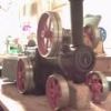
| 429 forum posts 268 photos | This is the gear train for the cams. The camshafts rotate counter to the crank. The blue gears (EN1A) are driven or drive and the orange/yellow (brass/nickel silver) ones idle.
This is quite a bit simpler than the full-size engine, which has compound gears, but it does resemble it. The gears are Mod 0.3 as I have a set of involute cutters. It would work in Mod 0.4 or 0.5 as well. This is part of the build I'm looking forward to most. Steve |
| Steve Crow | 15/11/2020 16:33:37 |
| 429 forum posts 268 photos | Now for the conrods. These were cut from 2mm clockmakers brass in strips of 4.
They were then tapped 12BA.
I forgot to take photos of the clamping half but they were made the same way. They were then separated with a jewellers saw.
I then screwed the two parts together, blended in the curves and tidied them up a bit. They were then drilled and reamed to 3mm.
These still need surface finishing. Steve |
| Steve Crow | 15/11/2020 16:56:51 |
| 429 forum posts 268 photos | Before I went any further, I thought I'd test fit them on the crank.
A fiddly job attaching these but everything fits and moves nicely with minimum play. The middle one at the front looks like it isn't straight but that's the camera angle.
I then tried the whole assembly in its bearings in the block.
The conrods do foul the block in parts but this is because they are no liners or pistons in yet so the rods are rotating more than intended.
I've got to say that it doesn't look like the bottom end of a racing engine - more like some late Victorian marine engine. The thickness of the conrods is massively overscale. This is a consequence of using the smallest screws I had. Even then, I had to turn down the heads to 1.8mm and dome them for clearance. This is also the reason why there is only two bearings. There just wasn't space for other journals. I'm happy to answer any questions or receive any criticism. Anyway, will update as I make more parts. Steve |
| Ady1 | 15/11/2020 18:57:47 |
 6137 forum posts 893 photos | Looks great With the scale of the work you are doing and the skill level you have reached it looks like you are at the edge of the normal tooling envelope Alternatively the watchmaker industry may offer solutions and ideas |
| Bob Wild | 15/11/2020 22:50:44 |
| 99 forum posts 77 photos | Very impressed!! |
| Steve Crow | 27/11/2020 15:34:42 |
| 429 forum posts 268 photos | I made this gadget (mandrel?) to hold the cylinder heads while I milled it and drilled and counterbored the inclined valve holes.
It is basically a 18mm diameter brass bar with 4mm removed on the flat. The silver steel rod is 8mm so I can hold it in various tool holders and collets.
The idea behind this is that the 16 degree inclined valves converge at a point 5mm below deck height, the bottom of the cylinder head. If I axially centre a cutting tool, I can do all the operations just by rotating 16 degs. either way. The above photo were taken after I'd used it, hence the square pattern of shallow holes where the drill (intentionally) broke through. Here it is set up and the flats being milled.
It took me a long time to set this up. I had to clock it axially and make sure it was centred both ends. It seemed like hours with a little rubber hammer tapping things true before I was happy. This was done before I attached the workpiece.
After that it was drilled 1.6mm through, c/bored 2mm for the valve guides and c/bored 2.7mm for the springs.
This worked a treat. My Y-axis remained locked for the whole process. Steve |
| Steve Crow | 28/11/2020 13:07:02 |
| 429 forum posts 268 photos | I made 3 cylinder heads, a left, a right and a universal. The universal is going to be used as a test-bed for cutting the valve seats and a couple of other things. After that it will go back on the mandrel and will be a sacrificial holder for the cam carrier blanks when it comes to machining them. There are 48 inclined holes here, that's 144 separate operations.
Here is the under side of the heads. The central holes were drilled at the same time as the holding down bolt holes.
Here is a close up. The web between the two valve holes is 0.1mm thick which I was a bit worried about as even the slightest variation from this between cylinders would be visible but everything came out alright.
A close up of the underside. The central hole is not for a miniature spark plug but a guide for the tool I'm going to make for cutting a recess.
All in all, I'm quite pleased with these. I can't find any errors so all the careful clocking and indexing paid off. Saying that, I'm glad it's over. It took me a whole day of dial-counting and double checking before drilling. Steve |
| Steve Crow | 07/02/2021 18:03:04 |
| 429 forum posts 268 photos | Hello, I haven't updated this thread for a while so here we go. I have been cutting the gears for the cam gear train, and lots of spares.
There are 11 gears in the train in 4 different sizes.
They all came out ok apart from the 20 tooth wheels which I didn't give enough depth of cut. Only a couple of thou but it's made a difference at Mod 0.3. This is unfortunate as 7 of the 11 gears are 20 tooth! I'm just going to have another go. To hold the wheels for facing, drilling etc. I made pot chucks for each size.
These just screw into a 8mm collet thingy.
They give a nice friction grip that doesn't do any damage. You don't need glue or shellac.
I made a spare of course.
I centre drilled one of each size as "test" gears. I'll fix an arbor to each and put them in my depthing tool and see how they mesh.
More soon.
Steve
Edited By Steve Crow on 07/02/2021 18:04:56 Edited By Steve Crow on 07/02/2021 18:05:53 |
| Roger Best | 07/02/2021 18:14:19 |
 406 forum posts 56 photos |
|
| Steviegtr | 07/02/2021 22:37:56 |
 2668 forum posts 352 photos | Nice work Steve. Keep it up. Steve. |
| Ron Laden | 08/02/2021 06:18:14 |
 2320 forum posts 452 photos | Very impressive I admire your patience and ingenuity in making those tiny parts, great stuff. Ron |
| Steve Crow | 08/02/2021 10:09:58 |
| 429 forum posts 268 photos | These are the cam carriers. I think that's the term. If someone has a better name for them, let me know.
They are about 80% finished. I just need to cut a groove for the cam bushes and drill and tap a few holes for end plates.
Made from 1/4 x 3/4 mild steel bar. Quite tricky milling operation with all the angles.
A total of 48 M1.2 holes to tap - I have done around half.
Steve |
| Steve Crow | 08/02/2021 10:12:25 |
| 429 forum posts 268 photos | Cam carriers and cylinder heads.
Steve Edited By Steve Crow on 08/02/2021 10:12:38 |
| Ady1 | 08/02/2021 14:04:01 |
6137 forum posts 893 photos | Amazing workmanship My eyes would explode after an hour of effort at that scale |
| Steve Crow | 01/03/2021 13:22:38 |
| 429 forum posts 268 photos | I made a start on the camshafts. First of all I turned the blanks and a couple of spares from 1/8" silver steel.
The brass gadget on the end is to support and provide a female centre for the shaft and also, when I move it in the collet chuck when milling, I can use the flat part for indexing and make sure all the lobes are of correct orientation.
Here they are sat on the cam carriers.
Here they are with the lobes milled.
Each lobe has 36 facets which I will have to file and polish out.
This is the cam profile I've tried to achieve. There is no science behind me using this shape - it's just easy to draw and "looks right".
It was difficult to get a photo of the profile but you can get a good idea from this one.
More soon, Steve Edited By Steve Crow on 01/03/2021 13:22:58 Edited By Steve Crow on 01/03/2021 13:33:13 |
| Steve Crow | 08/03/2021 14:20:57 |
| 429 forum posts 268 photos | I made some temporary arbors for the cam train gears and checked them with a depthing tool.
They meshed very nice and smoothly and the centre distance seemed bang-on as well. But, they just didn't look right in brass, it made everything look a bit "clockwork", so I remade them all in steel.
Here are the steel test gears with temporary arbors and a brass one for comparison.
Steve |
| Steve Crow | 03/12/2021 15:13:54 |
| 429 forum posts 268 photos | Hello, I haven't updated this in ages so here are a few images of where I am with the engine and gearbox.
I still have the pistons, valve springs and and a few minor things to make for the engine. For the gearbox, I have to make the forward/reverse gears. I also need to design a clutch that will fit in here-
The crossed-out side plates on the gearbox are tempory. I wanted to be able to see the diff but I've cut a "viewing window" in the top of the gearbox instead. The plates will be replaced with scale looking ones. There is till a lot of work in finishing and polishing not to mention blueing about 130 screws. More pictures soon. Steve |
| Dave S | 03/12/2021 16:40:22 |
| 433 forum posts 95 photos | Awesome work. Dave |
| Steve Crow | 03/12/2021 17:27:22 |
| 429 forum posts 268 photos | Any chance of a photo with a rule in it so we can get a true sense of the small scale? Dave I usually put something in my photos for scale - I forgot this time. To give you an idea, the total length of the assembled engine and gearbox is 85mm, 5mm longer than a cigarette. Next time I take some photos, I'll include a coin or something. Steve |
| Ady1 | 03/12/2021 18:18:01 |
6137 forum posts 893 photos | Looks great, a work of art |


Please login to post a reply.
Magazine Locator
Want the latest issue of Model Engineer or Model Engineers' Workshop? Use our magazine locator links to find your nearest stockist!
Sign up to our Newsletter
Sign up to our newsletter and get a free digital issue.
You can unsubscribe at anytime. View our privacy policy at www.mortons.co.uk/privacy
Latest Forum Posts
- hemingway ball turner
04/07/2025 14:40:26 - *Oct 2023: FORUM MIGRATION TIMELINE*
05/10/2023 07:57:11 - Making ER11 collet chuck
05/10/2023 07:56:24 - What did you do today? 2023
05/10/2023 07:25:01 - Orrery
05/10/2023 06:00:41 - Wera hand-tools
05/10/2023 05:47:07 - New member
05/10/2023 04:40:11 - Problems with external pot on at1 vfd
05/10/2023 00:06:32 - Drain plug
04/10/2023 23:36:17 - digi phase converter for 10 machines.....
04/10/2023 23:13:48 - More Latest Posts...
- View All Topics
Support Our Partners


Shopping Partners
Subscription Offer

Latest "For Sale" Ads
- Reeves** - Rebuilt Royal Scot by Martin Evans
by John Broughton
£300.00 - BRITANNIA 5" GAUGE James Perrier
by Jon Seabright 1
£2,500.00 - Drill Grinder - for restoration
by Nigel Graham 2
£0.00 - WARCO WM18 MILLING MACHINE
by Alex Chudley
£1,200.00 - MYFORD SUPER 7 LATHE
by Alex Chudley
£2,000.00 - More "For Sale" Ads...
Latest "Wanted" Ads
- D1-3 backplate
by Michael Horley
Price Not Specified - fixed steady for a Colchester bantam mark1 800
by George Jervis
Price Not Specified - lbsc pansy
by JACK SIDEBOTHAM
Price Not Specified - Pratt Burnerd multifit chuck key.
by Tim Riome
Price Not Specified - BANDSAW BLADE WELDER
by HUGH
Price Not Specified - More "Wanted" Ads...
Get In Touch!
Do you want to contact the Model Engineer and Model Engineers' Workshop team?
You can contact us by phone, mail or email about the magazines including becoming a contributor, submitting reader's letters or making queries about articles. You can also get in touch about this website, advertising or other general issues.
Click THIS LINK for full contact details.
For subscription issues please see THIS LINK.
Digital Back Issues


Donate

 Register
 Log-in
Model Engineer Magazine
- Percival Marshall
- M.E. History
- LittleLEC
- M.E. Clock

ME Workshop
- An Adcock
- & Shipley
- Horizontal
- Mill

Subscribe Now
- Great savings
- Delivered to your door

Pre-order your copy!
- Delivered to your doorstep!
- Free UK delivery!
All Forum Topics > Work In Progress and completed items > Cosworth V8 1:12 scale