Forum sponsored by:

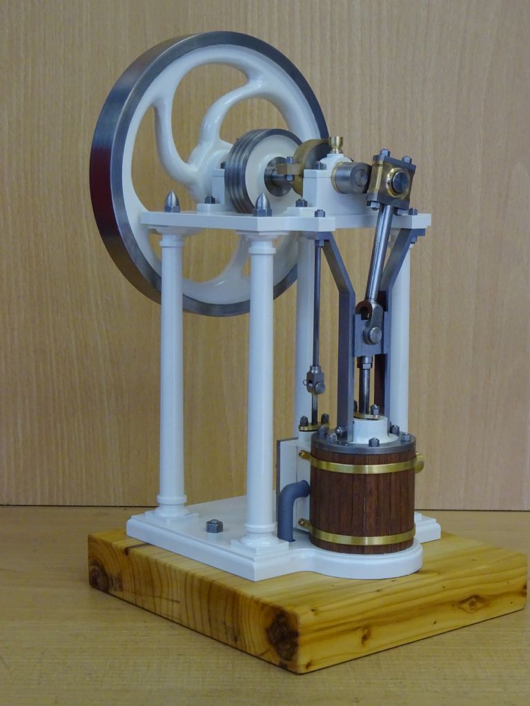
Muncaster's Simple Entablature Engine
| JasonB | 31/07/2019 06:56:54 |
 25215 forum posts 3105 photos 1 articles | Posted by Colin Heseltine on 30/07/2019 21:05:38:
Jason, That looks very nice. Do you have any video showing how you produced the radius around the cylinder mounting on the base plate and then changed from external radius to internal radius's and achieved it all nicely flowing from one radius to the next. Or was this done on your CNC machine? Colin Will explain it later if what I said in the article was not clear but the engine was made before I had the CNC. Edited By JasonB on 31/07/2019 07:14:31 |
| JasonB | 31/07/2019 07:27:33 |
25215 forum posts 3105 photos 1 articles | As for HP through a crank with support on one side I can beat Paul's with a 600HP Snow Engine and there are some big corliss steam engines about too. Edited By JasonB on 31/07/2019 07:28:23 |
| JasonB | 31/07/2019 19:26:53 |
25215 forum posts 3105 photos 1 articles | Posted by Colin Heseltine on 30/07/2019 21:05:38:
Do you have any video showing how you produced the radius around the cylinder mounting on the base plate and then changed from external radius to internal radius's and achieved it all nicely flowing from one radius to the next. Looking at the drawing at the bottom left of the base is a dimension of 22mm in from the edge to the ctr of the internal corner radius which I have marked in red which gives a distance from the cylinder Ctr datum point of 28mm (half base width less 22mm) in the X-axis and zero in the Y-axis. As the front edge of the base is 4mm from this point an 8mm cutter can be used as per the text.
First thing to do is set the rotary table up on the mill with it's axis directly below that of the mill and zero your handwheel dials or DRO. Then turn the table until the scale reads zero and clamp the work to the table with some packing between and make sure it is square to the lathes axis and the ctr of the cylinder is lined up to the mill spindle.
Pop an 8mm cutter in your holder of choice, lock the Y-axis at zero and then cut in from each edge to 28mm from the cylinder ctr. Assuming a bench top mill then something like 1mm deep per pass will do or more if you have sawn away most of the waste before milling. You should then end up with two slots like this.
Reposition the clamps to the sides and you can now also lock the X axis at -28, 0 and bring the cutter back down to take your first cut around the curve which will start from zero degrees and end at 180deg, repeat this until you have cut ring through and hopefully have a shape like this. before rushing to admire your work run the decorative moulding around the curve and front edges while the work is correctly located.
|
| JasonB | 09/08/2019 07:39:47 |
25215 forum posts 3105 photos 1 articles | Additional content to go with Part 2. The four embryo columns with the end spigots turned and ctr drilled.
This is the method I used to cut the tapers using a boring head to offset the centre but the same can be done by offsetting the tailstock. Hold by the bottom spigot with enough room to let the tool clear the cut and touch off against the 12mm diameter.
Zero the handwheel dial or DRO if you have one.
Wind the tool away by half the difference in diameters in this case 1mm [(10-8) / 2], my dial reads in diameter so I moved it 2mm (0.079" )
Now move the carrage so that the tool is at the other end of the work and you will see the gap
Now move the ctr towards you until the tool touches off on the work
It is now just a case of turning along teh length in a couple of passes preferably using power feed until your cross slide reads zero and you should end up with a nice taper.
Repeat for the other 3 columns
|
| Ron Laden | 09/08/2019 08:02:01 |
 2320 forum posts 452 photos | Not building this engine Jason but I always learn and pick up ideas and "how to do" from your build threads, would never have thought of using a boring head to offset the centre. Great stuff. |
| JasonB | 09/08/2019 08:02:32 |
25215 forum posts 3105 photos 1 articles | Cont'd Once the adhesive has set on the assembled columns they can be held in the chuck or a collet by the bottom spigot and using tailstock support the top square can be turned to it's finished thickness of 1.5mm.
Then reverse in the lathe so that the columns can be brought down to a final length of 119.5mm ensuring that all are the same length. After which the ends can be threaded.
You now have enough bit put together and get an idea of how the engine will look, cylinder still to be covered.
A shot of the feet being cut on the bearing pedestals which also brings the top block to length.
Edited By JasonB on 09/08/2019 08:03:13 |
| Ron Laden | 10/08/2019 08:25:17 |
2320 forum posts 452 photos | Jason, I have not turned any long tapers so was interested in the method you used on the columns, especially using the boring head for the offset. Unless I,m missing something the method must rely on flex in the spigot which is held in the collet..? I see the tapers are shallow at 2mm over the column length but there must obviously be a limit to how much offset can be applied relative to the spigot diameter..? |
| JasonB | 10/08/2019 10:00:07 |
25215 forum posts 3105 photos 1 articles | Yes Ron, The actual article says that there is enough flex to use this method. If the part was more rigid it would deed to be done between ctrs. The limit is probably dependent of the rigidity of your machine and how far you are willing to bend the column. |
| Rockingdodge | 13/08/2019 18:26:57 |
 396 forum posts 111 photos | Hi Jason, you mention using small metric sizes with fine threads, could you list the ones I would need along with taps and dies as mine start at M3 or would I be able to use BA sizes as I have 2 to 8 ba in stock. Regards Roger (newbie) |
| JasonB | 13/08/2019 19:15:22 |
25215 forum posts 3105 photos 1 articles | These are the metric sizes I show on the drawing. Metric Coarse which is the usual metric thread in M5, M4, M3, M2.5, M2 and M1.6 you would only need taps for M3, M2 and M1.6 if using studding, Dies also needed for the other sizes. Metric Fine in M6x0.75, M5x0.5 and M4x0.5 taps and dies for all. Alternatives Coarse M5 is only used for the piston rod to cross head joint. You could turn down the end of the rod to 4.7mm and thread 2BA or just use 3/16" rod which takes 2BA and adjust the holes it goes through in the cylinder cover and gland. In either cast just drill and tap the cross head for 2BA and you will also need a 2BA locknut which can be made or bought, if bought I tend to just thin down standard nuts. M4 This is used on the other end of the piston rod, crank pin and the column bottoms. All could be turned to 4.1mm and threaded 3BA M3 Just used for fixings so could easily be replaced with 5BA M2.5 This can be a straight swap with 7BA M2 Only used for the gland studs and nuts so 9BA will do for that M1.6 This is used to tap for the cladding band screws and would not matter if you went upto 9BA, heads could always be reduced in size. Fine M6x0.75 This is for the exhaust, if a thick say 1mm wall tube is used then you should be able to get away with M6 coarse or 0BA. Another option is to up the pipe size from 6mm OD to 1/4" and then use one of the ME series such as 1/4" x 40 or 1/4" x 32. M5x0.5 This is for the inlet so similar applies, thick wall and M5 coarse or come down to 3/16" pipe and use 2BA for thick wall or 3/16" x 40 for a thinner wall pipe. M4 x 0.5 Only used for the tops of the columns so you can get a few more turns of thread into the Acorn nuts and the bearing oilers and their sockets but could just use M4 coarse or adjust size to 4.1mm and use 3BA. It could be replaced with 5/32" x 40ME J |
| Rockingdodge | 13/08/2019 20:45:24 |
396 forum posts 111 photos | Thanks Jason, much appreciated. |
| JasonB | 23/08/2019 09:34:27 |
25215 forum posts 3105 photos 1 articles | Extra content to go with part 3 No so much to add this time round This photo shows how most of the waste was removed by working up through a series of ever increasing drills to 22mm before the final boring to 24mm.
This shot shows the port face of the cylinder being machined flat, I find that multiple passes with a small stepover using a sharp cutter gives a flatter finish than a couple of passes with a wide cutter particularly if there is any question about the tram of the machine. Here I used a 10mm cutter stepping over 2.5mm per pass.
The drawing for the cylinder having been reduced down to approx A5 for the mag may be a bit hard to read as it has quite a lot going on. You can download the A4 pdf from here which will print it out actual size and it will also blow up clearer on the screen than zooming into the mag image. Any questions just ask. |
| geoff walker 1 | 23/08/2019 11:39:19 |
| 521 forum posts 217 photos | Hi All, I've started making this engine, slow progress but always is with me. When I have the frame assembled I'll post some pics. Finally managed to get a copy of M.E. 4619, in Halifax of all places. WHS had a few copies, also MEW and EIM. I was curious Jason as to how you got such a neat radius on the top of the bearing cap. So simple really as shown in photo 15. Any of you chaps from Halifax, my first visit, a fine town, graceful old market, classic victorian town hall and of course the increasingly famous Piece hall. A beer festival in the latter this weekend, should be fun as long as all behave themselves. Geoff |
| JasonB | 23/08/2019 11:44:58 |
25215 forum posts 3105 photos 1 articles | Thank's Geoff, you will see the same method being used on the cylinder. |
| Mike Henderson 1 | 23/08/2019 22:18:24 |
| 29 forum posts | Hi, Jason. A quick query, if I may. I'm gathering the materials to make a start on this once the holidays are over. I notice that you call up the base as either steel or aluminium but for the entablature you specify steel. Is there a particular reason this can't be in aluminium as well? Thank, and thank you for preparing this design. I don't get as much hobby time as I'd wish and prefer projects that l can complete in a sensible timescale. MIke |
| JasonB | 24/08/2019 06:58:58 |
25215 forum posts 3105 photos 1 articles | Aluminium should be fine as well for the entablature. Don't think it would even hurt to do the columns in this if you have a light lathe, just a bit more expensive. |
| Rockingdodge | 30/08/2019 14:32:10 |
396 forum posts 111 photos | Hi Jason, couple of questions: I'm planning to make the cylinder out of alum alloy, could I take the bore out to 1"? My chunk has a hole already! I have plenty of gunmetal in stock but no suitable sizes of bronze, can I use this instead? Could pdf's of the plans to the correct scales be made available as they are printed in the mag, same as you have done with the cylinder? Thanks roger |
| JasonB | 31/08/2019 07:20:51 |
25215 forum posts 3105 photos 1 articles | I don't see any reason not to up the bore to 1", probably best to make the OD of the cylinder a bit larger say 29-30mm and to keep the shaping simple the valve chest and cover would need widening to match. Oil it up well after use to lessen any chance of corrosion. Assuming the Gunmetal is for bearings then yest that will be OK too, I would also use this or brass for the piston rather than risk the specified aluminium one picking up should it run on the now aluminium cylinder. J |
| Rockingdodge | 31/08/2019 11:38:12 |
396 forum posts 111 photos | Posted by JasonB on 31/08/2019 07:20:51:
I don't see any reason not to up the bore to 1", probably best to make the OD of the cylinder a bit larger say 29-30mm and to keep the shaping simple the valve chest and cover would need widening to match. Oil it up well after use to lessen any chance of corrosion. Assuming the Gunmetal is for bearings then yest that will be OK too, I would also use this or brass for the piston rather than risk the specified aluminium one picking up should it run on the now aluminium cylinder. J Thanks Jason, I've just found some 50mm dia ci so might use that instead. The bronze I have is LG2, is that suitable for bearing? Roger Edited By Rockingdodge on 31/08/2019 11:38:49 |
| JasonB | 31/08/2019 13:14:23 |
25215 forum posts 3105 photos 1 articles | That will do nicely and machines easily too. |


Please login to post a reply.
Magazine Locator
Want the latest issue of Model Engineer or Model Engineers' Workshop? Use our magazine locator links to find your nearest stockist!
Sign up to our Newsletter
Sign up to our newsletter and get a free digital issue.
You can unsubscribe at anytime. View our privacy policy at www.mortons.co.uk/privacy
Latest Forum Posts
- hemingway ball turner
04/07/2025 14:40:26 - *Oct 2023: FORUM MIGRATION TIMELINE*
05/10/2023 07:57:11 - Making ER11 collet chuck
05/10/2023 07:56:24 - What did you do today? 2023
05/10/2023 07:25:01 - Orrery
05/10/2023 06:00:41 - Wera hand-tools
05/10/2023 05:47:07 - New member
05/10/2023 04:40:11 - Problems with external pot on at1 vfd
05/10/2023 00:06:32 - Drain plug
04/10/2023 23:36:17 - digi phase converter for 10 machines.....
04/10/2023 23:13:48 - More Latest Posts...
- View All Topics
Support Our Partners


Shopping Partners
Subscription Offer

Latest "For Sale" Ads
- Reeves** - Rebuilt Royal Scot by Martin Evans
by John Broughton
£300.00 - BRITANNIA 5" GAUGE James Perrier
by Jon Seabright 1
£2,500.00 - Drill Grinder - for restoration
by Nigel Graham 2
£0.00 - WARCO WM18 MILLING MACHINE
by Alex Chudley
£1,200.00 - MYFORD SUPER 7 LATHE
by Alex Chudley
£2,000.00 - More "For Sale" Ads...
Latest "Wanted" Ads
- D1-3 backplate
by Michael Horley
Price Not Specified - fixed steady for a Colchester bantam mark1 800
by George Jervis
Price Not Specified - lbsc pansy
by JACK SIDEBOTHAM
Price Not Specified - Pratt Burnerd multifit chuck key.
by Tim Riome
Price Not Specified - BANDSAW BLADE WELDER
by HUGH
Price Not Specified - More "Wanted" Ads...
Get In Touch!
Do you want to contact the Model Engineer and Model Engineers' Workshop team?
You can contact us by phone, mail or email about the magazines including becoming a contributor, submitting reader's letters or making queries about articles. You can also get in touch about this website, advertising or other general issues.
Click THIS LINK for full contact details.
For subscription issues please see THIS LINK.
Digital Back Issues


Donate

 Register
 Log-in
Model Engineer Magazine
- Percival Marshall
- M.E. History
- LittleLEC
- M.E. Clock

ME Workshop
- An Adcock
- & Shipley
- Horizontal
- Mill

Subscribe Now
- Great savings
- Delivered to your door

Pre-order your copy!
- Delivered to your doorstep!
- Free UK delivery!
All Forum Topics > Stationary engines > Muncaster's Simple Entablature Engine