Forum sponsored by:

Stuart Twin Victoria (Princess Royal) Mill Engine
| JasonB | 31/07/2021 06:59:50 |
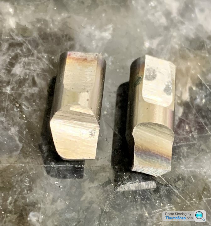
 25215 forum posts 3105 photos 1 articles | Any help, the leading edge on the left is angled back about 20-30deg
Edited By JasonB on 31/07/2021 07:01:08 |
| Dr_GMJN | 31/07/2021 07:33:47 |
 1602 forum posts | Posted by JasonB on 31/07/2021 06:59:50:
Any help, the leading edge on the left is angled back about 20-30deg
Edited By JasonB on 31/07/2021 07:01:08 OK thanks I’ll have a go. How come that angle is much larger now? What would happen if I duplicated what I have, but with a radius? |
| Ramon Wilson | 31/07/2021 08:03:53 |
 1655 forum posts 617 photos | Thanks Jason I have found the tool as above works well on cast Doc but it's not specific. If you are happy with your toolbit then by all means duplicate it with a decent radius - make sure that radius is backed off so it doesn't rub behind the cutting edge though. I'm off out for a family get together today so have a good session - hope it all goes well
Ramon
|
| Dr_GMJN | 31/07/2021 17:23:30 |
1602 forum posts | Thanks both. Ground another tool, this time with a radius: Cheers! |
| JasonB | 31/07/2021 18:01:37 |
25215 forum posts 3105 photos 1 articles | As the change in look is quite sudden it may have been a tiny hard spot or inclusion that just took the edge off the tool, should all come out when you hone or lap. |
| Ramon Wilson | 31/07/2021 22:59:24 |
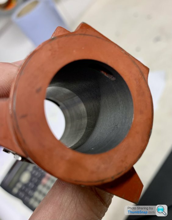
1655 forum posts 617 photos | Just got home Doc - to find a good result I would agree with Jason on the differing colour - if you can't feel it by lightly running a finger tip over it it's minimal and will easily disappear with lapping, though as said, I would think that's hardly neccessary but if you get satisfaction from lapping then certainly go for it. That's the first one done - you'll be an old hand at it after the second If that hole is open then a drop of JB scraped in and swiped off with a scalpel before it's fully set will eliminate any tendency for the sharp edge to affect whatever piston packing you decide to use.
|
| Dr_GMJN | 31/07/2021 23:21:54 |
1602 forum posts | Thanks for the comments both. I’m getting more of a feel for grinding tools now, and I can tell what sounds right or if something’s wrong. Cutting seems to have a distinctive sound that corresponds to a good surface finish and nicely formed chips, whereas even slight rubbing changes it. I checked the bore again, but I can’t detect any ridge with my finger, plus each end gives an identical vernier reading, so it can’t be anything serious I think. I did think about filling the screw hole break-throughs, I wondered if there was a chance the tiny bit of JB Weld might fall out though. I’ll try it before lapping anyway. So tomorrow I should get the other cylinder done, then it’s on to end facing with a mandrel. Apologies if I asked previously, but a few questions: 1) I assume the mandrel should be long enough to fit in the Chuck and to within perhaps 5mm of the end to be machined? The cylinder is quite long, so I did wonder if it should be stepped near the machined end, and have tail stock centre for support? 2) What’s the best material to use? 3) Should it taper at the Chuck end to fix it, or should it expand using a bolt? 4) Should I face, drill and tap the Chuck end first, so I can mount it in an angle plate on the mill, for determining the cylinder axis somehow?
|
| Ramon Wilson | 01/08/2021 09:08:23 |
1655 forum posts 617 photos | First off Doc, if the bores are not identical (unlikely) make any mandrel you do to fit the larger bore and do it first - the mandrel can be relieved to fit the smaller bore. Best to make the mandrel from mild steel - aluminium could be used but you do run the risk of galling. I would make the one for facing the ends an expanding mandrel the end of which is just inside the cylinder end - the cylinder wants to be as close as posssible to the chuck jaws. There should be no need for tailstock support. A second mandrel - a plain much simpler one - just a length of mild steel faced off one end and tapped for bolting to the angle plate the other end drilled and tapped for a clamp bolt. You could modify the expanding mandrel to do this of course but it's best left for something else in the future. If you can turn this second mandrel from something larger in diameter to give a larger flange for the bolting surface against the angle plate even better. Same thing goes regarding the largest first bore. With the cylinder ends faced it can be clamped in any radial position using a pre turned 'washer' I just use 6mm capheads for these tasks. The chances of a JBW repair to that hole coming out are virtually nil. Though not JBW I used a similar product -Loctite Metal Set - to do a similar repair to one of my Twin Vic's cylinders and that ran for a few years on steam at displays before many more on air without a hitch. JBW came along much later - every bit as good and far more cost effective! It's a 'Control Line Distraction' day today Ramon |
| JasonB | 01/08/2021 09:20:10 |
25215 forum posts 3105 photos 1 articles | Just one thing when making the mandrel which you will probably have to make from 30mm stock is to turn the part that fits the cylinder down to say 10thou oversize, drill, tap and then remove from lathe to saw the slots. You can now put it back into the chuck and finish turn using the cylinders as a ring gauge, this way the arbor stays in the chuck after finish turning and is therefore concentric |
| Dr_GMJN | 01/08/2021 09:47:00 |
1602 forum posts | Thanks again both. I was going to ask about that: after slitting the expanding mandrel, the final sizing cuts will obviously be intermittent for a bit? And I think I’ve asked before, but the expanding mandrel bolt hole should be drilled, then tapped with a first tap so that the thread tapers to nothing and gets pushed out with the bolt? Maybe taper the end of the bolt too. Re. Ramon’s point about the bores being identical - I noted down the exact micrometer reading for the bit protrusion for the last cut, which I will use again for the second one. I’m assuming that if I’m taking a similarly shallow final cut, the bores should be the same? I guess final depth of cut is the thing that could change that? I think the perfect 1.0000” bore on the first was a fluke; I’d calculated the need for one more cut, but instinct told me to creep up on the diameter and triple check just to be sure. The readings made me smile anyway. Ramon - As well as this, I’m trying to finish a 1:72 Airfix Swordfish floatplane that I’d pretty much given up on in February, it’s one of those that’s fought me every step, but I put so much effort into additional details that I couldn’t just leave it. So I’m splitting my hobby time at present. Plastic and iron is a nice contrast at least. Cheers.
|
| JasonB | 01/08/2021 10:01:10 |
25215 forum posts 3105 photos 1 articles | Yes using a taper tap is usual . As for sizing I tend to use the part to gauge final fit of the mating part |
| Ramon Wilson | 01/08/2021 10:37:01 |
1655 forum posts 617 photos | I see no reason why the taper from a taper tap could not be used but I have always used a caphead screw of varying diameters for the expasion bolt. I have een countersunk screws used for this too but the angle is really too obtuse to ease the torque required. Heres a short example made for a I/C cylinder head
I have several capheads from 8 ba to 6mm which have had a 60* included angle turned on them. The mandrel is roughed out to with .5 and 1mm on diameter drilled and tapped. the head needs to be no more than 8mm or so wide - the relief is there for nothing more that to enable the jaws to spring easier. Removed, the slots are put in (by hacksaw) then returned to the lathe and the hole heavily centred with a centre drill. Insert the screw until it just nips up then turn the diameter to suit the component. This way the expanding bolt can be flush and is expanding with equal force across the four 'legs' and requires little torque to establish a firm grip. The mandrel is uniform in diameter throughout it's length but the component does need to be as close a sliding fit as possible. Even with careful measurement given the nature of the boring bar you will do exceptionally well to achieve to identical bores but - you never know My car's packed, I need to do my lunch and I'm off out 'circulating' - 'plastic' comes later Best - Ramon
|
| Dr_GMJN | 01/08/2021 11:48:09 |
1602 forum posts | Thanks Ramon. Re identical bores, you said before “..if the bores are not identical (unlikely)..” which I thought ‘hmmm, that’s optimistic! I assumed you meant to say they would be different, so no problem. Plenty to do so I’ll report back as and when. I think I need to get a bit of mandrel steel on Monday, but first the other bore. |
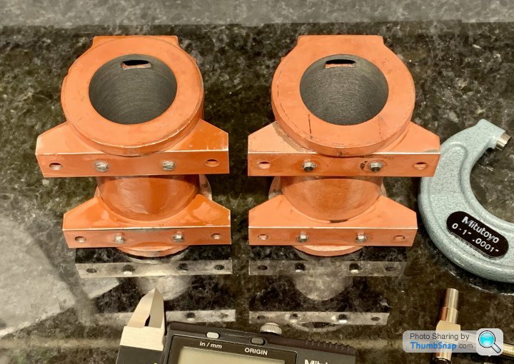
| Dr_GMJN | 01/08/2021 17:53:05 |
1602 forum posts | Second cylinder setup - pretty much a case of undoing the bolts and substituting the part. Vertical slide just needed to go down a fraction. |
| Ramon Wilson | 01/08/2021 21:27:34 |
1655 forum posts 617 photos | That's an excellent result Doc - both finish and dimensionally When you finish turn the mandrel do as Jason suggested and use the cylinders to size the mandrel but in case there's the slightest difference in bores try both each time and do, as said, the larger one first. You should be well pleased with the outcome - looks like you've made a real good start to a nice long journey Ramon
|
| Dr_GMJN | 01/08/2021 22:39:43 |
1602 forum posts | Posted by Ramon Wilson on 01/08/2021 21:27:34:
That's an excellent result Doc - both finish and dimensionally When you finish turn the mandrel do as Jason suggested and use the cylinders to size the mandrel but in case there's the slightest difference in bores try both each time and do, as said, the larger one first. You should be well pleased with the outcome - looks like you've made a real good start to a nice long journey Ramon
Yes, very happy with that, glad it’s done. I wouldn’t have tried to size the mandrel using the dials - I was going to use the angled topside method to enable very small cut increments when I get close. Cheers. |
| Dr_GMJN | 04/08/2021 22:55:43 |
1602 forum posts | Made a start on the first mandrel. I’ve had this before with mild steel, but no matter what tips or speeds or feeds I try, I can’t get a good finish. I got EN1A from my local supplier - he knows his stuff so I’m confident it’s right. |
| JasonB | 05/08/2021 06:54:06 |
25215 forum posts 3105 photos 1 articles | Double check that the tool is not slightly too high and make sure tip is not damaged or worn |
| Ron Laden | 05/08/2021 07:30:06 |
 2320 forum posts 452 photos | I don't know but is the rearward angle of the tool OK for that type of insert, I use CCMT inserts and mainly have the leading edge of the insert perpendicular to the work. Just wondered. What I should have said is the insert the right tool for general turning and finishing to size.? Edited By Ron Laden on 05/08/2021 07:56:53 |
| Dr_GMJN | 05/08/2021 07:56:06 |
1602 forum posts | Thanks both. I’ve tried brand new inserts to no avail. The end was faced with that tool, and it seemed spot-on for height. |


Please login to post a reply.
Magazine Locator
Want the latest issue of Model Engineer or Model Engineers' Workshop? Use our magazine locator links to find your nearest stockist!
Sign up to our Newsletter
Sign up to our newsletter and get a free digital issue.
You can unsubscribe at anytime. View our privacy policy at www.mortons.co.uk/privacy
Latest Forum Posts
- hemingway ball turner
04/07/2025 14:40:26 - *Oct 2023: FORUM MIGRATION TIMELINE*
05/10/2023 07:57:11 - Making ER11 collet chuck
05/10/2023 07:56:24 - What did you do today? 2023
05/10/2023 07:25:01 - Orrery
05/10/2023 06:00:41 - Wera hand-tools
05/10/2023 05:47:07 - New member
05/10/2023 04:40:11 - Problems with external pot on at1 vfd
05/10/2023 00:06:32 - Drain plug
04/10/2023 23:36:17 - digi phase converter for 10 machines.....
04/10/2023 23:13:48 - More Latest Posts...
- View All Topics
Support Our Partners


Shopping Partners
Subscription Offer

Latest "For Sale" Ads
- Reeves** - Rebuilt Royal Scot by Martin Evans
by John Broughton
£300.00 - BRITANNIA 5" GAUGE James Perrier
by Jon Seabright 1
£2,500.00 - Drill Grinder - for restoration
by Nigel Graham 2
£0.00 - WARCO WM18 MILLING MACHINE
by Alex Chudley
£1,200.00 - MYFORD SUPER 7 LATHE
by Alex Chudley
£2,000.00 - More "For Sale" Ads...
Latest "Wanted" Ads
- D1-3 backplate
by Michael Horley
Price Not Specified - fixed steady for a Colchester bantam mark1 800
by George Jervis
Price Not Specified - lbsc pansy
by JACK SIDEBOTHAM
Price Not Specified - Pratt Burnerd multifit chuck key.
by Tim Riome
Price Not Specified - BANDSAW BLADE WELDER
by HUGH
Price Not Specified - More "Wanted" Ads...
Get In Touch!
Do you want to contact the Model Engineer and Model Engineers' Workshop team?
You can contact us by phone, mail or email about the magazines including becoming a contributor, submitting reader's letters or making queries about articles. You can also get in touch about this website, advertising or other general issues.
Click THIS LINK for full contact details.
For subscription issues please see THIS LINK.
Digital Back Issues


Donate

 Register
 Log-in
Model Engineer Magazine
- Percival Marshall
- M.E. History
- LittleLEC
- M.E. Clock

ME Workshop
- An Adcock
- & Shipley
- Horizontal
- Mill

Subscribe Now
- Great savings
- Delivered to your door

Pre-order your copy!
- Delivered to your doorstep!
- Free UK delivery!
All Forum Topics > Work In Progress and completed items > Stuart Twin Victoria (Princess Royal) Mill Engine