Forum sponsored by:

Colchester Student Mk1 Won't Start
| Richard Kirkman 1 | 20/04/2020 12:39:52 |
| 334 forum posts 799 photos | Didn't get much done yesterday, but still progress I took the door and cupboard off to clean inside, then I cut some bits of lino to go in the drawer and shelves to make them a bit nicer to use. It works very well. I had some left over from putting it in my tool chest. Then I played around smacking the door and drawer with mallet to try and get them to close properly (there was more finess than that, but it was just playing)
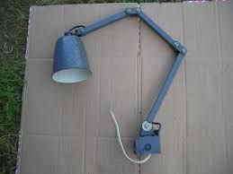
Also, looking at the light, which needs a good clean, it might need some parts replacing or modifying. It seems that one of the arms has snapped. It still works fine and stays in place, but I think I may play with it as I clean it
Anyway, I chainsawed up logs yesterday afternoon, so I need to rough out 16 bowls for drying or they'll crack. That'll keep me busy for a few days |
| Phil Whitley | 20/04/2020 15:28:48 |
 1533 forum posts 147 photos | WOW, that is the original Colchester angle poise lamp, now selling for a small fortune as a covetted item of "Industrial art" so named by a bunch of yuppies who call themselves antique dealers and specialise is industrial heritage items! Mine has a "common" MEM Memlite, which they only sell for £75.00! I am well green! Phil.
|
| Richard Kirkman 1 | 25/04/2020 23:12:03 |
| 334 forum posts 799 photos | Just finished all the woodworking for the while, more lathe work to follow. Still no lightbulb. Royal Mail signed for 1-3 days more like 1-whenever it comes. Hopefully next week. It'll be nice to have better light on the lathe. I need to finish a bottle opener for someone, then I'll clean up the light
|
| Richard Kirkman 1 | 30/04/2020 12:27:55 |
| 334 forum posts 799 photos | Emailed the lighting company and they said they've had delays of 2 weeks and more, so might not be here to test till next week. This Friday at the earliest. If anyone's posting anything, don't use royal mail. |
| Herman van der Merwe | 08/05/2020 05:42:50 |
 180 forum posts | Hi Richard, Phil directed me to your thread from the Colchester lathe group on groups.io where I help out. I am just starting almost exactly the same restoration work on my Student as you have done so far, so I am reading your posts with interest. Good job so far! At the moment I am restoring (OK let's rather say installing) the wiring on the lathe. Would it be possible to take some more pictures as to the route the yellow wires follow from the drawer switch back to the wiring panel? My lathe has most of the wires removed, so I have no idea where the run the new wires. Thanks, Herman |
| Richard Kirkman 1 | 08/05/2020 11:56:42 |
| 334 forum posts 799 photos | Hi Herman, Just read through your thread. I'll try to get you as many pictures as I can, maybe a video if you're able to view it like my other videos. Is it just the wiring of the limit switches that you need? Nice to be helping someone else out for once... On another note, it's 3 weeks since the light bulb was posted so I've emailed asking them to send another one out. Meanwhile, I've been enjoying putting the lathe to use. I'm definitely getting more comfortable using the machine and I'm trying to consider my accuracy. I had two hammer ends lying around, so I thought I would put them to use and make myself a small mallet from some scrap aluminium I had. I think It turned out quite nicely, even with a wood turned Bubinga handle. Not a typical mallet but interesting for me to try some setups.
When I was tidying up the machine after, I decided to stick my hand in one of the holes under the headstock. Turned out it was absolutely full of old swarf and grime. It's made me really want to take the headstock off and clean in there, but it seems a bit excessive. Anyway, it's interesting to see all the old chips, completely steel, no aluminium, and some of the swarf must have been at least 10mm depth of cut on the radius. So more clues that the machine has been used plenty. Surprisingly I didn't find any bolts in the hole, but I did pull out loads of shavings, I can't quite reach the bottom, but the machine is probably 1kg lighter
I'll get those videos this afternoon Herman With regards to your last post on the Colchester forum, My wires are not free, they go through a pipe that goes all the way through the base of the lathe. Edited By Richard Kirkman 1 on 08/05/2020 11:58:44 |
| Richard Kirkman 1 | 08/05/2020 15:41:45 |
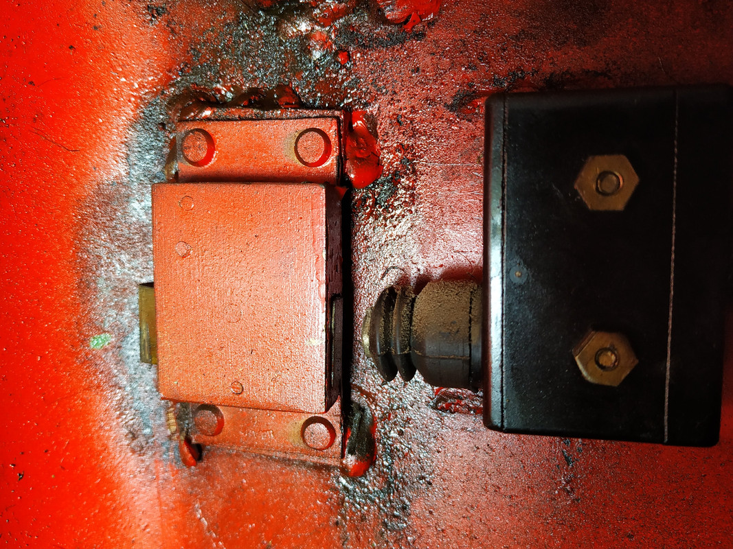
| 334 forum posts 799 photos | Couldn't really get enough access for a video My wiring is exactly as Phil directed, so that diagram explains it all The red blue and yellow come from the contactor and overloads in their specified place, then all 3 wires head out the back and up to where the cover switch is. At this point, the yellow goes into and comes out of the cover safety switch
The yellow then goes out of the switch and down the tube going through the lathe body
Then it heads through into the coolant tank
Orientation might be messed up, but i'm sure you can figure it out
In the coolant tank
Then out into where the drawer is
So the wire coming from the cover switch comes into the key switch, then heads straight back up along the tube, then up and into the limit switch. I hope that helps a bit, happy to answer any questions or get pictures for anything. Just ask. I'm very interested to see how you will wire yours up. Also, while i was taking pictures of wiring I did a bit of cleaning, brightened up quite well
|
| Herman van der Merwe | 08/05/2020 20:44:14 |
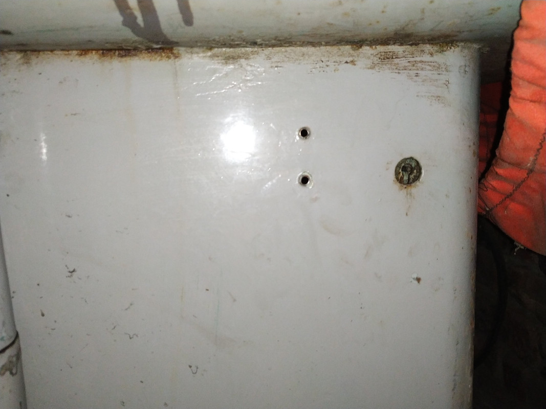
180 forum posts | Thanks for all the pictures Richards. It really helps a lot. It is interesting that your lathe has a removable plate onto which the key switch is mounted. My lathe does not have this plate and it is simply mounted on the body side.
I love your hammer. You are going to use that a lot when you are doing aluminium and copper work. The wiring I am still thinking about. I discussed what I should do with two factory electrical engineer mates of mine and they recommend that I wire it up to current standards but keep the old equipment I have in place. This means I will install three contactors (one which was present). The first contactor will be to activated the key switch is turned and will make the electrical panel live. The second contactor will be to activate the motor and the third the fluid circulation pump. Fuses will remain in place but be replaced in function by a three pole circuit breaker. That is as far as I have given it thought. I am thinking of starting a thread of the rebuild somewhere on a forum so that others can learn as well. |
| Richard Kirkman 1 | 09/05/2020 12:19:44 |
| 334 forum posts 799 photos | Good Luck Herman, I'm sure Phil will get you sorted if you get stuck. Looking closely at the pictures of your lathe, it's definitely not identical to mine. The castings on the gearbox look different, letters aren't the same shape, and the two speed levers on the top of the headstock are running on a surface instead of being free like mine. It could be an earlier model, but I'm no expert. I'm not quite sure why you're doing it with 3 contactors when one seems to work fine like in mine? Anyway, If you do start a thread, please post a link here so anyone interested can see!
|
| Herman van der Merwe | 09/05/2020 13:35:38 |
180 forum posts | Mine is a 1953 model. If you look at https://colchesterlathe.groups.io/g/main/files/Serial%20numbers you can find your lathe's year of manufacture with the serial number as stamped in the tail end of the bed. I am still in two minds regarding the wiring, but would like to get to our standards but retaining the original equipment as far as possible. Yes, I am going the thread route as there could be others wanting to go the same route we did. Will post a link here for sure! |
| Herman van der Merwe | 11/05/2020 10:33:02 |
180 forum posts | What thickness nitrile rubber did you use for the gaskets? |
| Richard Kirkman 1 | 11/05/2020 13:16:26 |
| 334 forum posts 799 photos | I used 1mm thick nitrile rubber It was plenty thick enough A sheet of 500x500 should be more than enough to replace every gasket in the lathe |
| Herman van der Merwe | 12/05/2020 12:13:51 |
180 forum posts | As requested Richard here is a linky to my restoration project. 1953 Colchester Student Mk1 6" gap bed - A restoration project |
| Richard Kirkman 1 | 12/05/2020 12:30:58 |
| 334 forum posts 799 photos | Posted by Herman van der Merwe on 12/05/2020 12:13:51:
As requested Richard here is a linky to my restoration project. 1953 Colchester Student Mk1 6" gap bed - A restoration project Thank you, I'll be reading along, maybe even see if I can help at some point In the picture of my limit switch you've posted, my wiring is wrong so if you do get one, don't do it like that. Do it like Phils! |
| Herman van der Merwe | 12/05/2020 12:55:55 |
180 forum posts | Any idea how to get the spindle's chuck cone loose? |
| Richard Kirkman 1 | 12/05/2020 13:02:41 |
| 334 forum posts 799 photos | Posted by Herman van der Merwe on 12/05/2020 12:55:55:
Any idea how to get the spindle's chuck cone loose? If by chuck cone you mean the L0 taper part, that's part of the main spindle, so the whole spindle must be removed which I have covered earlier in this thread. There is also a guide in the manual I sent. |
| Herman van der Merwe | 12/05/2020 16:11:13 |
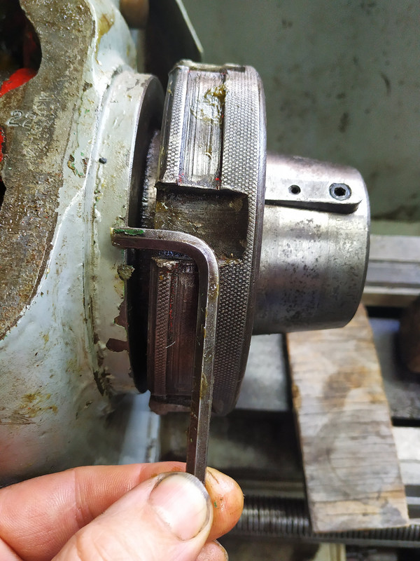
180 forum posts | If you look at the attached photo you will see that I cannot fit anything between the nut and the cap screw head. I did read your forum post and the manual's section, but alas my lathe's spindle is different. It looks like the cone part can unscrew.
|
| Richard Kirkman 1 | 12/05/2020 16:16:17 |
| 334 forum posts 799 photos | Okay fair enough. Having the l0 taper screw on and off defeats the point of the taper though. So I don't think it screws off.
Could you try removing the whole spindle? |
| Herman van der Merwe | 14/05/2020 22:05:29 |
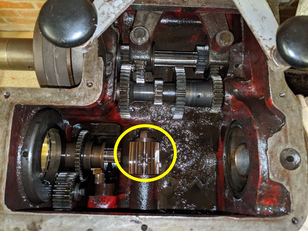
180 forum posts | Hi Richard, you might have seen on groups.io that I did get the spindle out after a LOT of struggling. How did you manage to get this gear off the shaft? Mine does not want to move.
|
| Richard Kirkman 1 | 14/05/2020 22:22:15 |
| 334 forum posts 799 photos | Yes I have seen. Very interesting stuff, I wasn't expecting your spindle to be anything like that. Enjoying your thread a lot! The gear was quite hard to get off. There's a locknut on the end of the shaft which must be removed, then there's a washer then the gear comes off. However, my gear was quite stuck. Eventually, after a lot of pulling and pushing and cutting my knuckles on the gears behind it, I managed to work it off. I didn't take out the other gear shaft, but If you have then it should be much easier access as I struggled and ended up pulling and pushing on the actual handle which risked damaging it. Luckily nothing broke for me, but it's worth mentioning. Then, if memory serves, there is a leather washer behind the gear which acts as a gasket. My lathe was leaking from that shaft so I made a new leather washer which I made very tight to make sure it didn't leak anymore (1 month later, it's still not leaking) Then just reassemble in the opposite order. Good luck
I'm not sure that yours will be the same as mine. I'll have a look at the pictures of yours |


Please login to post a reply.
Magazine Locator
Want the latest issue of Model Engineer or Model Engineers' Workshop? Use our magazine locator links to find your nearest stockist!
Sign up to our Newsletter
Sign up to our newsletter and get a free digital issue.
You can unsubscribe at anytime. View our privacy policy at www.mortons.co.uk/privacy
Latest Forum Posts
- hemingway ball turner
04/07/2025 14:40:26 - *Oct 2023: FORUM MIGRATION TIMELINE*
05/10/2023 07:57:11 - Making ER11 collet chuck
05/10/2023 07:56:24 - What did you do today? 2023
05/10/2023 07:25:01 - Orrery
05/10/2023 06:00:41 - Wera hand-tools
05/10/2023 05:47:07 - New member
05/10/2023 04:40:11 - Problems with external pot on at1 vfd
05/10/2023 00:06:32 - Drain plug
04/10/2023 23:36:17 - digi phase converter for 10 machines.....
04/10/2023 23:13:48 - More Latest Posts...
- View All Topics
Support Our Partners


Shopping Partners
Subscription Offer

Latest "For Sale" Ads
- Reeves** - Rebuilt Royal Scot by Martin Evans
by John Broughton
£300.00 - BRITANNIA 5" GAUGE James Perrier
by Jon Seabright 1
£2,500.00 - Drill Grinder - for restoration
by Nigel Graham 2
£0.00 - WARCO WM18 MILLING MACHINE
by Alex Chudley
£1,200.00 - MYFORD SUPER 7 LATHE
by Alex Chudley
£2,000.00 - More "For Sale" Ads...
Latest "Wanted" Ads
- D1-3 backplate
by Michael Horley
Price Not Specified - fixed steady for a Colchester bantam mark1 800
by George Jervis
Price Not Specified - lbsc pansy
by JACK SIDEBOTHAM
Price Not Specified - Pratt Burnerd multifit chuck key.
by Tim Riome
Price Not Specified - BANDSAW BLADE WELDER
by HUGH
Price Not Specified - More "Wanted" Ads...
Get In Touch!
Do you want to contact the Model Engineer and Model Engineers' Workshop team?
You can contact us by phone, mail or email about the magazines including becoming a contributor, submitting reader's letters or making queries about articles. You can also get in touch about this website, advertising or other general issues.
Click THIS LINK for full contact details.
For subscription issues please see THIS LINK.
Digital Back Issues


Donate

 Register
 Log-in
Model Engineer Magazine
- Percival Marshall
- M.E. History
- LittleLEC
- M.E. Clock

ME Workshop
- An Adcock
- & Shipley
- Horizontal
- Mill

Subscribe Now
- Great savings
- Delivered to your door

Pre-order your copy!
- Delivered to your doorstep!
- Free UK delivery!
All Forum Topics > Help and Assistance! (Offered or Wanted) > Colchester Student Mk1 Won't Start