Forum sponsored by:

Model Turbines
Sharing information about model turbines
| Turbine Guy | 24/06/2021 15:08:18 |
| 541 forum posts 578 photos | I received the casting of Drag Cover 5 described in the 04/06/2021 post from Shapeways. The following photos show the front and back of the casting and the drawing shows the design cast dimensions with the actual dimensions in parenthesis.
|
| Werner Jeggli | 24/06/2021 21:51:32 |
| 28 forum posts 6 photos | Hello Byron, Viewing your pictures it appears to me that the quality of the cast is disappointingly low. I compare it with a bronce cast exhaust insert I received from shapeways some time ago. But then, this later item was much smaller. Perhaps they used a different casting technique ? Werner |
| Turbine Guy | 25/06/2021 00:38:31 |
| 541 forum posts 578 photos | Hi Werner, I agree, this was not one of their best castings. The following photos shows the first drag turbine cover and housing I purchased. These are the same size of castings but the edges appear to be a little sharper and the finish smoother than in the pictures I showed in my last post. I think this casting will still cleanup okay and probably work. Thanks for your comments, Byron
Edited By Turbine Guy on 25/06/2021 00:41:21 |
| Turbine Guy | 26/06/2021 17:35:23 |
| 541 forum posts 578 photos | I made the following table to show the first test results for the Drag Turbine running on air using different combinations of rotors and cover plates. The housing, number of shim washers, bearings, and propeller are the same for each test. I assumed Drag Cover 5 would improve the performance of either rotor, but the first test with the nozzle diameter of 0.028 only helped Drag Rotor 5. Apparently, the reduction in mass flow caused by the small nozzle size reduced the power more than the impact of the flow directed at the rotor improved the power. I will start increasing the nozzle size in Drag Cover 5 and run the tests of this cover with each rotor again until I find the nozzle size that gives the best performance. The nozzle size shown in the table is essentially as cast and is the size of the drill that would pass through the cast hole. The air pressure is higher than I was getting for other tests with nozzles this size, so the surface may not be smooth.
|
| Turbine Guy | 27/06/2021 18:41:38 |
| 541 forum posts 578 photos | I drilled out the nozzle of Drag Cover 5 from 0.028” to 0.029”. The following picture shows the drill in the holder I use after it has gone all the way through. The picture also shows what the inside surface of this cover looks like after all the machining and rubbing on an oilstone. Removing the smallest amount at a time is very easy with this holder. Although the increase in nozzle size was very small, the speed of the GWS EP 2.5x0.8 propeller increased approximately 500 rpm for each rotor with a corresponding increase in power of approximately 0.1 watt. The air pressure was 24 psig with the 0.029 nozzle size which is closer to what I was getting for this nozzle size before. When I finish finding the nozzle size that gives the highest performance for each of the rotors, I will update the table shown in my last post.
|
| Turbine Guy | 01/07/2021 20:31:48 |
| 541 forum posts 578 photos | I finally got all the drills I needed to find the optimum nozzle size for Drag Cover 5. When I increased the nozzle size with a #68 drill (0.031" Edited By Turbine Guy on 01/07/2021 20:36:56 Edited By Turbine Guy on 01/07/2021 20:38:31 |
| Turbine Guy | 02/07/2021 19:27:15 |
| 541 forum posts 578 photos | I found the nozzle size for Drag Cover 5 that gives the most power from my airbrush compressor for each of the rotors. The following table shows the results of my last tests. For Drag Rotor 2, the maximum power of approximately 1.3 watts was with a nozzle size of 0.032”. For Drag Rotor 5, the maximum power of approximately 0.9 watts was with nozzle sizes greater than or equal to of 0.031”. The angling of the nozzle in the direction of rotation of Drag Cover 5 only increased the maximum power 0.1 watt using Drag Rotor 2. Drag Cover 5 increased the maximum power using Drag Rotor 5 by 0.9 watts. I assumed that angling the nozzle in the direction of rotation would increase the power for all nozzle sizes for both rotors. The tests indicated Drag Cover 5 only outperformed the combination of Drag Cover 3 and Drag Rotor 2 when the input energy was the highest. This indicates that the impact of the gas has a negative effect on creating the channel flow rotation the gives the maximum drag on the rotor. If this is true, there should be another increase in power using Drag Rotor 2 and Drag Cover 5 when the nozzle size is large enough that the impact does not reduce the creation of a higher drag coefficient significantly. Increasing the nozzle size any further in Drag Cover 5 might reduce the power when using Drag Rotor 5.
|
| Turbine Guy | 04/07/2021 19:09:52 |
| 541 forum posts 578 photos | I tried increasing the nozzle size in Drag Cover 5 a few more times as shown in the following table, but the performance of Drag Rotor 2 never improved. The only reason I could think of that the angled nozzle wasn’t improving the performance was ball bearing friction. The ball bearings had a lot of use without adding oil between the test I made in March and the tests I made in July. The drag turbine has much higher bearing loads due to the gas pressure pushing on a large amount of the rotor front face. This causes a large axial load that is not very good for the type of ball bearings I use. Also, the pressure in the housing forces some of the working gas to pass through the ball bearings and probably carry out some oil. I decided to try adding new Krytox GPL 102 oil and run a test with each cover plate and everything else unchanged. Running these two tests with new oil and immediately after the first test, will have the condition of the ball bearings close to identical. I ran the drag turbine for several minutes until the speed stabilized at its highest value before running the next test immediately after. The Krytox GPL 102 oil is less viscous than the Krytox GPL 105 oil I use for running on steam but more viscous than the AeroShell Fluid 12 oil that came with the ball bearing. The last two tests in the table show that the performance was improved with the angled nozzle. The speed and power will slowly increase as the oil thins out but will always be lower with the Krytox GPL oil running on air than the AeroShell Fluid 12 oil that comes with the ball bearings.
|
| Turbine Guy | 05/07/2021 20:33:10 |
| 541 forum posts 578 photos | I ran Drag Turbine 5 on steam using the Stuart 504 boiler and the GWS EP 2508 propeller. I used Drag Rotor 2 since it worked better than Drag Rotor 5. The following table gives the results of the test. The turbine wouldn’t spin when I first tried to run it with the 0.007” total shim thickness used for running on air. I reduced the total shim thickness to 0.005”. The 0.002” extra clearance freed up the binding caused by thermal expansion. Drag Turbine 5 ran at a maximum speed of 28,000 rpm after the bearing oil warmed up and the excess oil leaked out. The speed stayed near the maximum for most of the test but started to drop a little as the wick burners slowly ran out of fuel. The boiler ran out of water before the wick burners ran out of fuel. Because of the binding of the turbine at the start of the test, I couldn’t measure the time to use all the ¾ cup of water. The angled nozzle of Drag Cover 5 worked well with steam raising the power from 2.5 watts to 4.2 watts. This matched the best performance of any of my turbines running on steam from the Stuart 504 boiler and using Krytox GPL 105 oil.
|
| Turbine Guy | 07/07/2021 21:33:28 |
| 541 forum posts 578 photos | Posted by Turbine Guy on 22/04/2020 12:21:41:
This chart, also shown in the post of 14/03/2019, is copied from ‘A Study Of High Energy Level, Low Output Turbines’ prepared by Dr. O. E. Balje for the Department of the Navy in December 1957. This chart illustrates the maximum performance he estimated for various types of turbines when optimized. The heavy solid lines in the chart are for axial turbines. The dashed lines are for Terry turbines. The thin solid lines are for Drag turbines. The drag turbines are like turbine pumps. The blades circulate the flow in a way that increases the drag force on the rotor. The units for the volume flow are ft*3/sec and lb/ft^3 for the gas density. The values of Ns and Ds for Turbine 3 for the test of 3/4/2020 are 1.0 and 14.9 respectively. The efficiency of an optimized Terry turbine with these values of Ns and Ds from the chart is approximately 16% and the efficiency of Turbine 3 was 14.3% based on my most conservative values of the power required by the propeller. I’ll get into the Reynolds number effects and how they lower the efficiency of the optimum Terry turbine below that of my turbine for this particular case in the next post. This post and the post that followed explained why I believed that my tangential turbines could in some cases exceed the performance of Terry turbines designed by Dr. Balje's guidelines. When I used the supersonic velocity correction and the Reynolds number corrections the chart the efficiency was very close to my test results with air. When I used a correction for moisture in addition to the other corrections, the performance of my tests with steam also was close to the performance estimated by this chart. I will compare the performance of Drag Turbine 5 running on steam to the performance estimated by this chart for drag turbines in my next post.
|
| Turbine Guy | 08/07/2021 19:07:25 |
| 541 forum posts 578 photos | I ran Drag Turbine 5 again with everything the same as in the 05/07/2021 post. The results were the same except I was able to use my stopwatch to find the approximately 8 minutes it took to use all the ¾ cup of water in the boiler. The resulting mass flow is approximately 2.9 lb/hr. Assuming the steam was saturated, the enthalpy drop from a pressure of 27 psig is approximately 76 btu/lb and the energy available to the turbine is approximately 65 watts. The efficiency of Drag Turbine 5 for this test was approximately 6.5%. The specific speed Ns and the specific diameter Ds as defined in the chart of the last post are 1.1 and 8.4 respectively. The efficiency of a drag turbine meeting all the design requirements is estimated to be approximately 25% as shown in the chart of the preceding post. The report gives corrections in efficiency for conditions that don’t meet what was assumed in the report. For a 0.039” diameter nozzle and a mass flow of 2.9 lb/hr, the percent moisture is estimated to be approximately 19%. The efficiency correction for this amount of moisture is 0.75. The Reynolds number is 46,200 and is lower than the assumed minimum of 200,000. The efficiency correction for this Reynolds number is 0.48. The clearance between the cover and the rotor face is 0.003” that is larger than the assumed clearance of 0.0006” and the efficiency correction for the excess clearance is 0.96. The blade thickness of .010’” is larger than the assumed blade thickness of 0.006 and the efficiency correction factor for the excess thickness is approximately 0.90. The estimated efficiency is reduced to approximately 7.8% with these corrections. The actual turbine efficiency of 6.5% is still lower than the estimated value of 7.8% but the corrections show the main causes for the low efficiency. |
| Turbine Guy | 09/07/2021 18:42:03 |
| 541 forum posts 578 photos | I ran the Drag Turbine again with everything the same as in the 08/07/2021 post except I used Drag Rotor 5. I decided to call the combination of Drag Rotor 2 and Drag Cover 5 as Drag Turbine 4 and the combination of Drag Rotor 5 and Drag Cover 5 as Drag Turbine 5. I updated the following table to show the results of the test. It took approximately 7 minutes to use all the ¾ cup of water in the boiler. The resulting mass flow is approximately 3.3 lb/hr. Assuming the steam was saturated, the enthalpy drop from a pressure of 35 psig is approximately 89 btu/lb and the energy available to the turbine is approximately 87 watts. The efficiency of Drag Turbine 5 for this test was approximately 6.2%. I will compare the actual efficiency with the efficiency predicted by the chart shown in the post of 07/07/2021 with the corrections as discussed in the last post. It is interesting that the pressure increased (35 psig vs 27 psig) with Drag Rotor 5 compared with Drag Rotor 2 even though everything else was the same and the throttle valve was fully open. The increase in inlet pressure would have to be caused by an increase in pressure in the flow channel or by blockage in the nozzle. Blockage of the nozzle would reduce the mass flow and power so there must have been an increase in pressure in the flow channel. Apparently the open pockets work better than the blades when the mass flow is large enough and pointed in a direction that helps to reduce the leakage. Edited By Turbine Guy on 09/07/2021 19:07:12 |
| Turbine Guy | 11/07/2021 18:07:00 |
| 541 forum posts 578 photos | Posted by Turbine Guy on 12/12/2020 19:49:29:
Probably the biggest advantage of the drag turbine over the impulse turbines running on very low input energies, is the effect of Reynolds number. The Reynolds number tends to drop dramatically with very low input energies. This causes a corresponding loss in efficiency for impulse turbines but has almost no effect on drag turbines. The drag turbines were given their name since they relied on increasing the drag force on the rotor to much higher levels than the drag force on the flow channel. Even though the increased drag on the rotor is caused by the dynamic effects of the spiral flow, it is treated like a viscous drag in the analysis. I realized in my 08/07/2021 post that I used the correction for low Reynolds number to show one of the reasons for the performance of my drag turbine being less than what was predicted by the chart of the 07/07/2021 post. This correction does not apply to the drag turbines and as I mentioned in the part of the 12/12/2020 post I show above, was one of the reasons I felt this type of turbine would work well for low power models. I need to revaluate why my drag turbines did not perform as well as predicted by the chart. Edited By Turbine Guy on 11/07/2021 18:13:11 |
| Turbine Guy | 14/07/2021 16:06:07 |
| 541 forum posts 578 photos | The 12/03/2021 Post shows the first test results of Drag Turbine 3. The most significant finding of this test was how sensitive the performance was to the clearance between rotor and cover plate. Changing this distance by approximately 0.001” changed the pressure in the channel from 9.5 psig to an average of 5.8 psig. I looked through my tests where I determined the optimum total thickness of shims and the drag turbine speed could change by about 2,000 rpm with a change of one 0.001” thick shim. The effect of the leakage is especially severe when using low energy sources like an airbrush compressor. The reduction in power with increasing blade thickness, especially without a sharp edge, is also a big factor. This was demonstrated by the better performance of Drag Rotor 5 with the open buckets compared with Drag Rotor 2 with thick blades without sharp edges. Even though the Drag Rotor 5 had a relatively large amount of extra leakage area it outperformed Drag Rotor 2 when both were used with Drag Cover 5 and run on steam. The correction factors for the blade thickness and leakage given by ‘A Study Of High Energy Level, Low Output Turbines’ prepared by Dr. O. E. Balje for the Department of the Navy in December 1957 that I used do not appear to sufficient for the small mass flows of my airbrush compressor and small boiler. |
| Roger Best | 15/07/2021 13:54:36 |
 406 forum posts 56 photos | Hi Turbine Guy just to let you know I am still following your excellent work. I mostly read your posts from the e-mail because of a glitch on my computer but I occasionally load the tread to look at the tables, etc.. As such I probably don't increment the tally for number of readers.
|
| Turbine Guy | 15/07/2021 20:58:49 |
| 541 forum posts 578 photos | Thanks for your kind remarks Roger. I'm trying to generate an interest in making small model turbines. I hope by showing the different designs I've tried and how well they worked or the problems I've had, will be of some help. Several people have added some very useful information to this thread. This sharing of information is what I hoped would happen. |
| Turbine Guy | 19/07/2021 15:51:29 |
| 541 forum posts 578 photos | My goal when I made my first model turbine was to make a turbine that was competitive with the small Stuart ST oscillating cylinder steam engines I had at the time I made my first turbine. After I retired, I decided to try using the same type of engineering I used to design full size steam turbines of from 8 hp to over 200 hp. I’ve shown in this thread and the Testing Models thread the methods I’ve used to engineer, design, make, and test my turbines. Some of the engineering worked as well with model turbines, but as I quickly found out, there are problems much more difficult to overcome in very tiny turbines using very low energy sources. These problems don’t just affect turbines but can be just as difficult to overcome with steam engines. The following table shows the best test results I have been able to obtain for the types of turbines I made and the types of steam engines I purchased fully machined. As you can see from the table, the steam engines also struggle to make much power with low energy sources. Even though the maximum available energy from my smallest boiler using a single wick burner is approximately double the maximum available energy from my airbrush compressor (40 watts vs 18 watts at 25 psig), most of the models performed better with air. Although the power outputs are quite low, the Saito Steam Boat video shows they are capable of powering small boats. I will explain what I think are the strengths and weaknesses of each of these designs in the next post.
Edited By Turbine Guy on 19/07/2021 15:55:58 |
| Turbine Guy | 20/07/2021 16:37:54 |
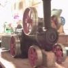
| 541 forum posts 578 photos | I added the two steam engine models to the table in the last post to use as a comparison in performance with model turbines using the same energy sources. I thought that this comparison would illustrate that obtaining high efficiency is very difficult for all types of models running on low energy power sources. The Testing Models thread shows what I found from testing, to be the strengths and weaknesses of my small model steam engines shown in the picture below. The steam engine on the right is a Stuart Turner ST. It is a double acting oscillating cylinder engine with a 7/16” (11.1 mm) bore and stroke. The steam engine in the center is a Saito T-1. It is a single action piston valve engine with a 8.8 mm bore and 12 mm stroke. The engine on the left is a Miniature Steam Models (MSM) Tyne. It is a double acting oscillating cylinder engine with a 11 mm bore and stroke. Since this is a model turbine thread, I’ll leave it up to the Testing Models thread to show the strengths and weaknesses I have found for my model steam engines.
Edited By Turbine Guy on 20/07/2021 16:49:54 Edited By Turbine Guy on 20/07/2021 16:51:45 |
| Turbine Guy | 21/07/2021 16:26:15 |
| 541 forum posts 578 photos | I’ll start with Drag Turbine 5 in my discussion of the strengths and weaknesses of the turbines shown in the table of the 19/07/2021 post. Although this turbine did not perform well with the low energy input used in the tests for that table, it started to show promise when the energy input was higher as shown in the table of the 09/07/2021 post. The following drawing shows the Drag Turbine 5 assembly. The rotor, housing, and cover plate are all castings made by Shapeways. I would be glad to send the step files these casting were made from and the drawings necessary to do the machining to anyone that would like them. I had them made of bronze but they could be made from any of the materials and methods used by Shapeways that are applicable to the step files. The step files assume a uniform 2% shrinkage that I show in earlier posts worked out about right for these parts. If you opt for a material that has a different shrink rate, there might not be enough allowance for machining to the sizes shown in the drawing. I tried to minimize the amount of material to cut costs and speed up reaching temperature when running on steam. The advantages of this turbine are: The disadvantage of this turbine are: |
| Turbine Guy | 22/07/2021 19:53:53 |
| 541 forum posts 578 photos | The two types of impulse turbines shown in the table of the 19/07/2021 post are axial and tangential flow. I'll start with the tangential flow. Tangential Turbine 3 SD + Gap was the last experiment of a long list of things that were tried to improve the efficiency. It was found that increasing the number of pockets and overlapping the pockets improved the efficiency. I started with Tangential Turbine 1 that had 24 pockets without overlap, then Tangential Turbine 2 with 48 overlapping pockets, and ending with Tangential Turbine 3 with 60 overlapping pockets. Each time the number of pockets increased the efficiency improved. Velocity staging was tried on Tangential Turbine 3 which had a rotor with two rows of blades and a reversing chamber to take the flow exiting from the first row and directing it into the inlet side of the second row. The small increase in performance with the velocity staging did not justify the large amount of extra complication. The housing of Tangential Turbine 3 was modified to add a nozzle in a position that would allow the rotor to be entirely overlapped with a close clearance and the outer face of the rotor was opened up as described in the 27/09/2020 Post. This forced the flow to exit the rotor from the side rather than the outer diameter and is indicated with an SD for side discharge. Opening up the rotor, changed the amount the flow was turned from 180 degrees to 164 degrees but eliminated the counterbore required for peripheral discharge. This change improved the efficiency with air or steam. The last thing tried was using a gap to allow the flow from the non-diverging sonic nozzle to expand to supersonic velocity before contacting the rotor as described in the 24/05/2021 Post and shown in the following drawing. I found this gap was necessary when testing Axial Turbine 2 that will be discussed in the next post.
|


 that is the next larger drill size from the size used in the previous post, I could not get a constant turbine speed or inlet pressure. I removed the air supply tube from the inlet of Drag Cover 5, clamped a 5/32” dowel pin in the tube to block the flow, and ran the airbrush compressor. The pressure immediately went to the maximum pressure setting of 30 psig and the compressor shut off. The pressure maintained at 30 psig for several minutes with the compressor turned off indicating that there was no leakage upstream of the cover plate. I put the air supply tube back on the inlet of Drag Cover 5 and made sure it was tightly clamped. The pressure still varied between a high of approximately 21 psig and a low of approximately 19.5 psig. The air pressure was much more consistent in earlier tests, so I took the cylinder cover off the airbrush compressor and inspected the insides. Everything was clean and no build up of particles like shown in the


Please login to post a reply.
Magazine Locator
Want the latest issue of Model Engineer or Model Engineers' Workshop? Use our magazine locator links to find your nearest stockist!
Sign up to our Newsletter
Sign up to our newsletter and get a free digital issue.
You can unsubscribe at anytime. View our privacy policy at www.mortons.co.uk/privacy
Latest Forum Posts
- hemingway ball turner
04/07/2025 14:40:26 - *Oct 2023: FORUM MIGRATION TIMELINE*
05/10/2023 07:57:11 - Making ER11 collet chuck
05/10/2023 07:56:24 - What did you do today? 2023
05/10/2023 07:25:01 - Orrery
05/10/2023 06:00:41 - Wera hand-tools
05/10/2023 05:47:07 - New member
05/10/2023 04:40:11 - Problems with external pot on at1 vfd
05/10/2023 00:06:32 - Drain plug
04/10/2023 23:36:17 - digi phase converter for 10 machines.....
04/10/2023 23:13:48 - More Latest Posts...
- View All Topics
Support Our Partners


Shopping Partners
Subscription Offer

Latest "For Sale" Ads
- Reeves** - Rebuilt Royal Scot by Martin Evans
by John Broughton
£300.00 - BRITANNIA 5" GAUGE James Perrier
by Jon Seabright 1
£2,500.00 - Drill Grinder - for restoration
by Nigel Graham 2
£0.00 - WARCO WM18 MILLING MACHINE
by Alex Chudley
£1,200.00 - MYFORD SUPER 7 LATHE
by Alex Chudley
£2,000.00 - More "For Sale" Ads...
Latest "Wanted" Ads
- D1-3 backplate
by Michael Horley
Price Not Specified - fixed steady for a Colchester bantam mark1 800
by George Jervis
Price Not Specified - lbsc pansy
by JACK SIDEBOTHAM
Price Not Specified - Pratt Burnerd multifit chuck key.
by Tim Riome
Price Not Specified - BANDSAW BLADE WELDER
by HUGH
Price Not Specified - More "Wanted" Ads...
Get In Touch!
Do you want to contact the Model Engineer and Model Engineers' Workshop team?
You can contact us by phone, mail or email about the magazines including becoming a contributor, submitting reader's letters or making queries about articles. You can also get in touch about this website, advertising or other general issues.
Click THIS LINK for full contact details.
For subscription issues please see THIS LINK.
Digital Back Issues


Donate

 Register
 Log-in
Model Engineer Magazine
- Percival Marshall
- M.E. History
- LittleLEC
- M.E. Clock

ME Workshop
- An Adcock
- & Shipley
- Horizontal
- Mill

Subscribe Now
- Great savings
- Delivered to your door

Pre-order your copy!
- Delivered to your doorstep!
- Free UK delivery!
All Forum Topics > Stationary engines > Model Turbines