Forum sponsored by:

Further Adventures with the Sieg KX3 & KX1
A thread for new owners of these machines to post in.
| JasonB | 03/09/2020 14:14:19 |
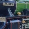
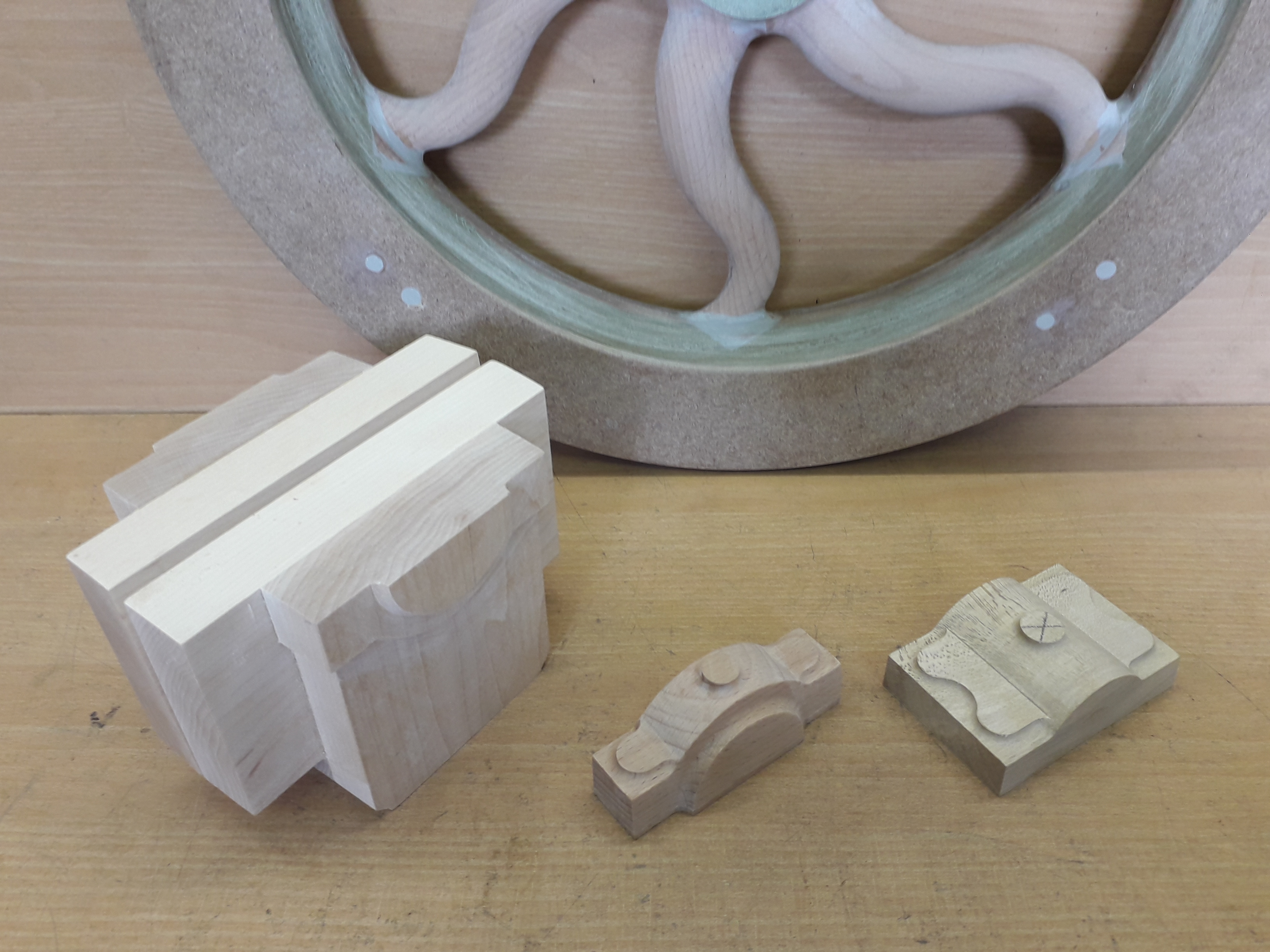
 25215 forum posts 3105 photos 1 articles | Just to conclude the pattern making session I thought I would add a couple of posts of the finished flywheel pattern. The almost 400mm dia rim was too big to turn so I did it on the mill, the "s" shaped curve on the inner edge was cut using co-ordinates from Alibre . This is where a DRO on the Z is handy as often the step is very small and hard to do with handwheel graduations.
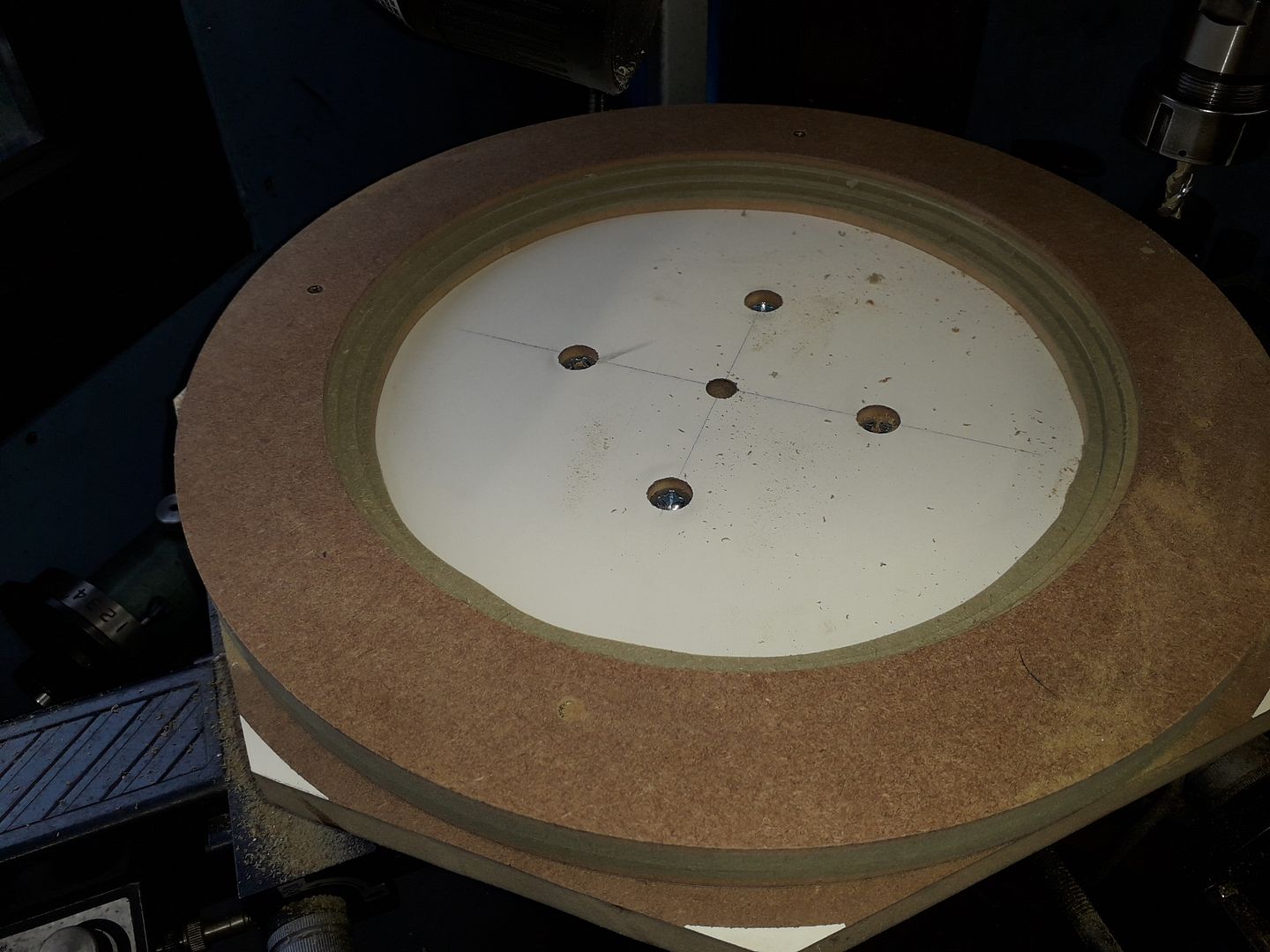
The spokes were then built into the rim and a disc of 6mm MRMDF added to the hub to both bring it upto thickness as well as add some strength to the spoke joints. The 2deg draft angle was cut by packing one side of the rotary table, same method for outside of the rim.
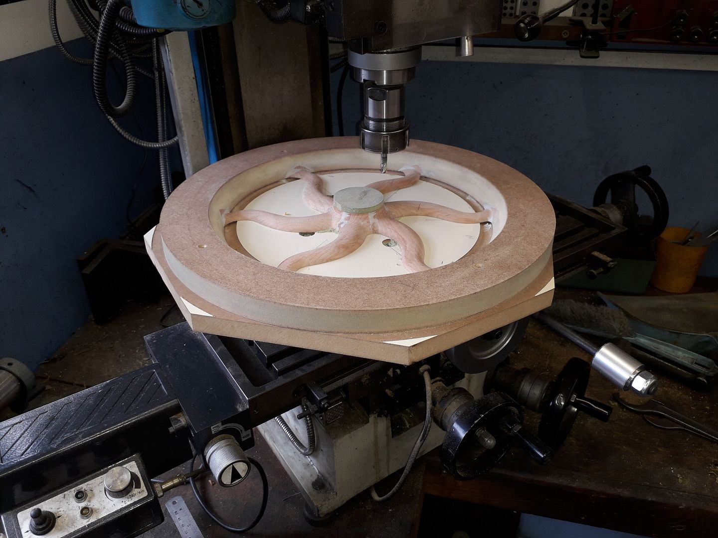
After a bit of filler and sanding it was done
All the patterns together
Edited By JasonB on 03/09/2020 14:14:50 |
| JasonB | 20/09/2020 17:06:21 |
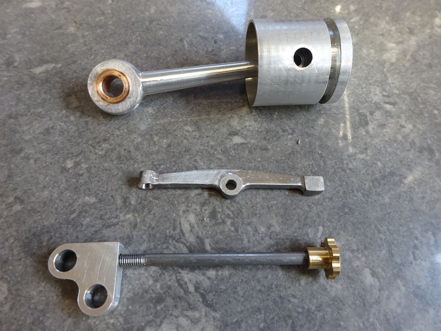
25215 forum posts 3105 photos 1 articles | With the possible loss of some of the F360 functions I thought I should get a few bits that I already had drawn out run through their CAM and knock them out.
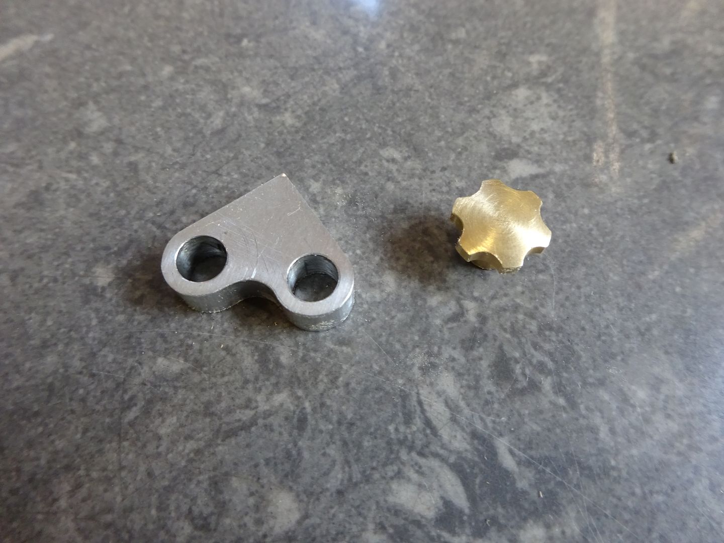
First up were a couple of simple 2D contouring jobs being the timing bracket and a knob to lock it's position for the Thompson engine, couple of holes also done on the CNC for the bracket.
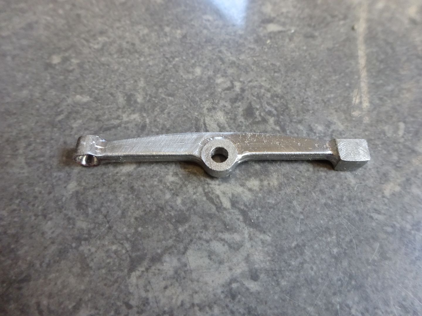
Then the rocker arm for the same engine from steel roughed out with 3D adaptive and then shaped with "steep & Shallow"
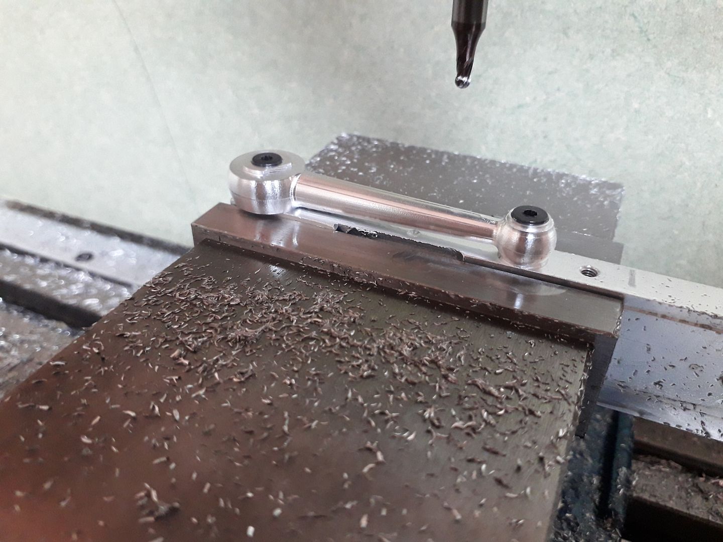
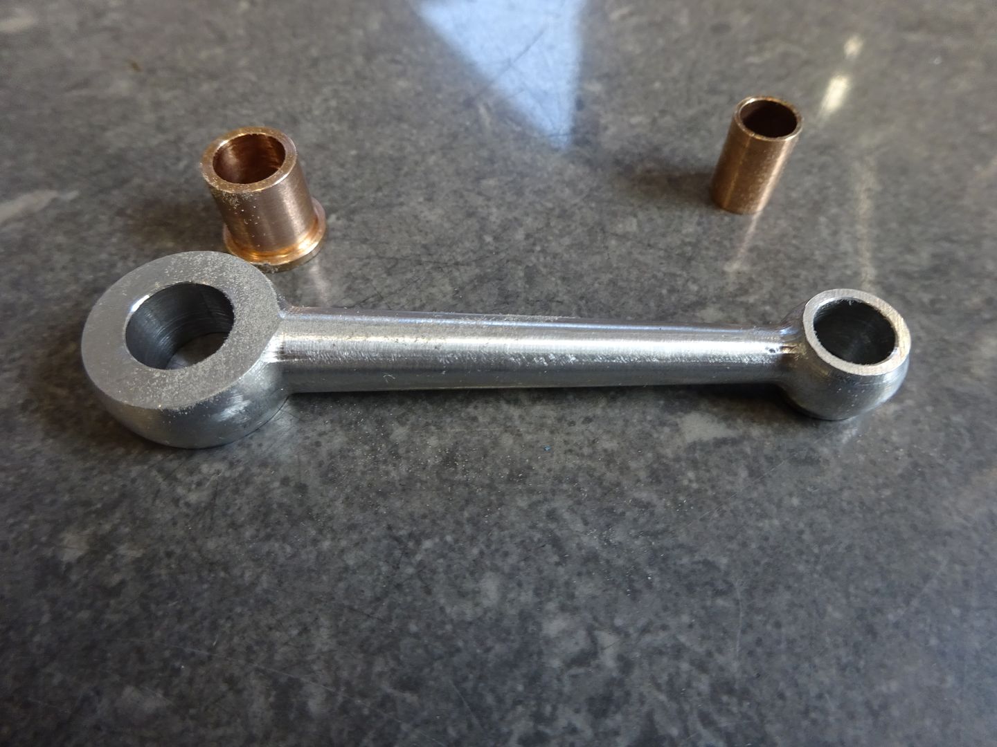
Finally the conrod, a rectangular blank was milled down from some round 2014 and the two holes reamed on the manual mill then these holes were used to hold the blank while the 3D adaptive and Steep & shallow did their thing.
|
| Nicola Casali | 02/11/2020 16:24:40 |
| 33 forum posts 6 photos | What post processor are you using with Fusion 360? I've done all of my CNC'ing on the KX3 with Aspire. I'm now trying Fusion 360, but haven't a clue what post processing to use. In Aspire I just select "Mach2/3 Arcs (mm)". Is there a config file available I can import? Thanks! |
| JasonB | 02/11/2020 16:59:27 |
25215 forum posts 3105 photos 1 articles | I just use F360's PP, when you click the PP icon this box comes up and if you click the highlighted arrow a whole list of choices comes up, just select Mach3mill and it will default to that in future.
|
| JasonB | 02/11/2020 18:38:06 |
25215 forum posts 3105 photos 1 articles | With another stint of pattern making that I can't disclose at the moment out of the way it was time to get back to making metal swarf in the form of the external shaping of a crankcase for a small version of the 36cc Wall 2-stroke. |
| Nicola Casali | 02/11/2020 18:58:26 |
| 33 forum posts 6 photos | Posted by JasonB on 02/11/2020 16:59:27:
I just use F360's PP, when you click the PP icon this box comes up and if you click the highlighted arrow a whole list of choices comes up, just select Mach3mill and it will default to that in future. I saw Mach3mill, but was not 100% certain this was the correct PP. Very helpful. Thank you. I can't wait to try it out. |
| JasonB | 07/11/2020 16:32:19 |
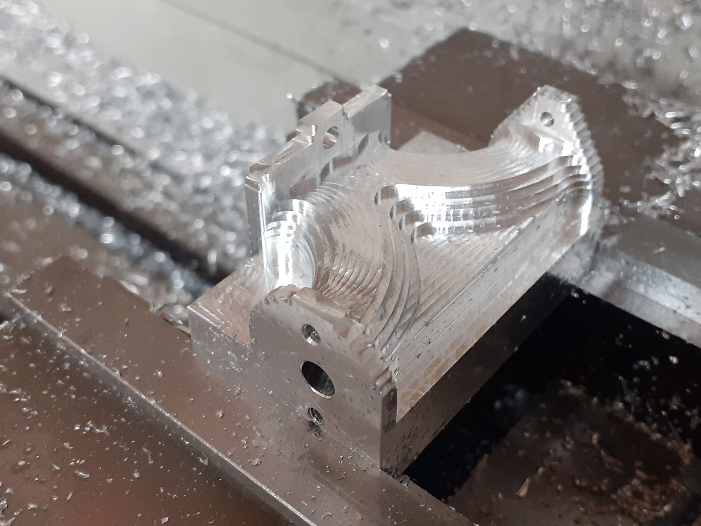
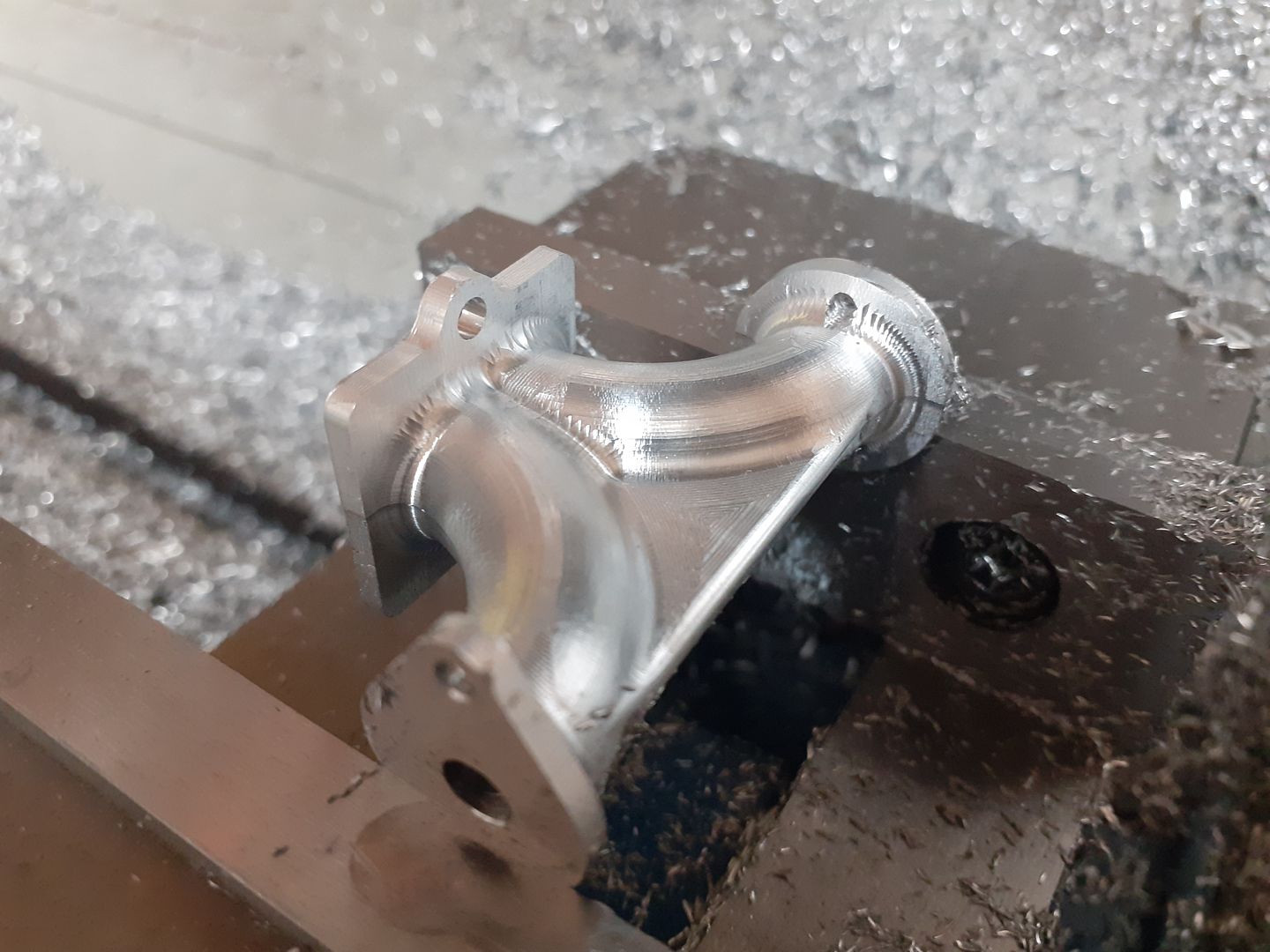
25215 forum posts 3105 photos 1 articles | I started this combined inlet and exhaust manifold for the Wall engine yesterday and completed the finish cut on teh second side this morning. First side after adaptive clearing which was done with a 5mm 2-flute cutter for Aluminium from Arc's premium range. Run at 5000rpm, 300mm/min feed, 5mm high x 1mm deep cuts to remove most of the waste then it stepped up 1mm at a time to leave a part looking like this.
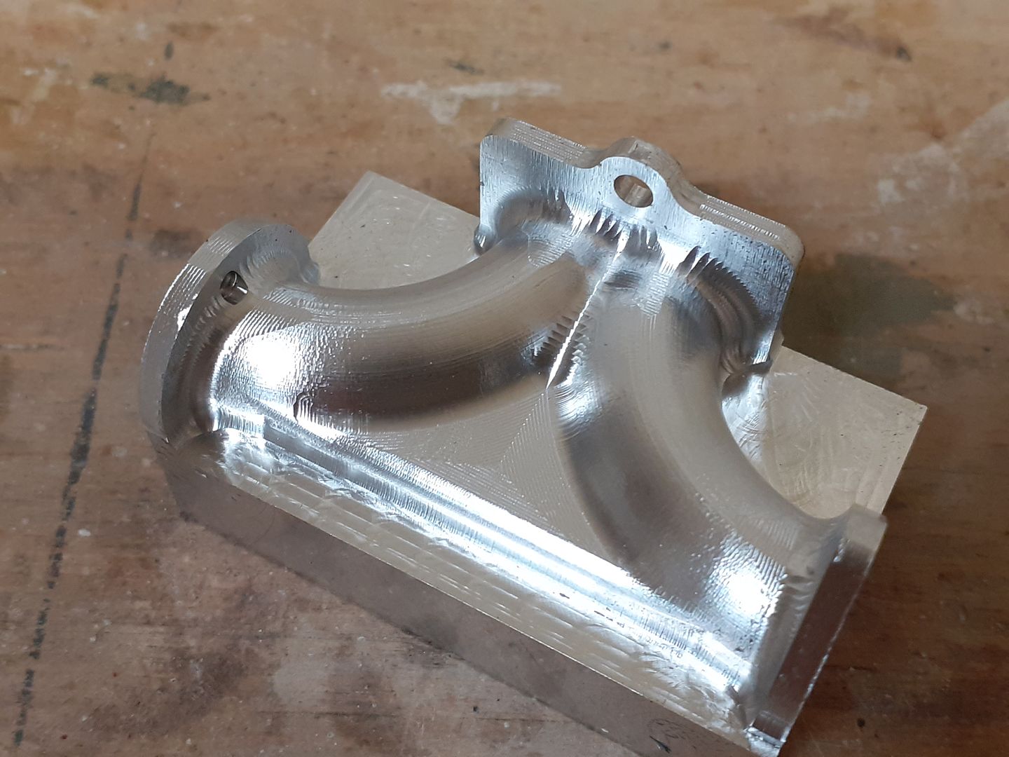
Then a "steep and shallow" finish pass with a 4mm dia 2-flute ball nose cutter for aluminium from APT as they do them with a 4mm shank which I needed to reach down the side of the rectangular flange. This was also run at 5000rpm and 300mm/min feed the scallop spacing was set at 0.25mm which takes a while but gives a nice finish.
Then it was basically do it all again for the other side but as the end flanges are different shapes a second setup was used in fusion with the bottom of the work now the top
As it will fit onto the side of the engine. Holes were drilled and tapped while it was still a rectangular block on the manual mill and I was happy that the drilled passages did not appear as the external shape was cut.
Edited By JasonB on 07/11/2020 16:39:20 |
| Ian Johnson 1 | 07/11/2020 18:31:48 |
| 381 forum posts 102 photos | That turned out great Jason nice work. It looks like one of those jobs which will be awkward to fabricate or cast. I use Vectric Vcarve on the KX1 which has some 3d ability but I'm not sure if it's as clever as fusion 360, i need to play around with it to test if it's any good. IanJ |
| JasonB | 07/11/2020 18:43:28 |
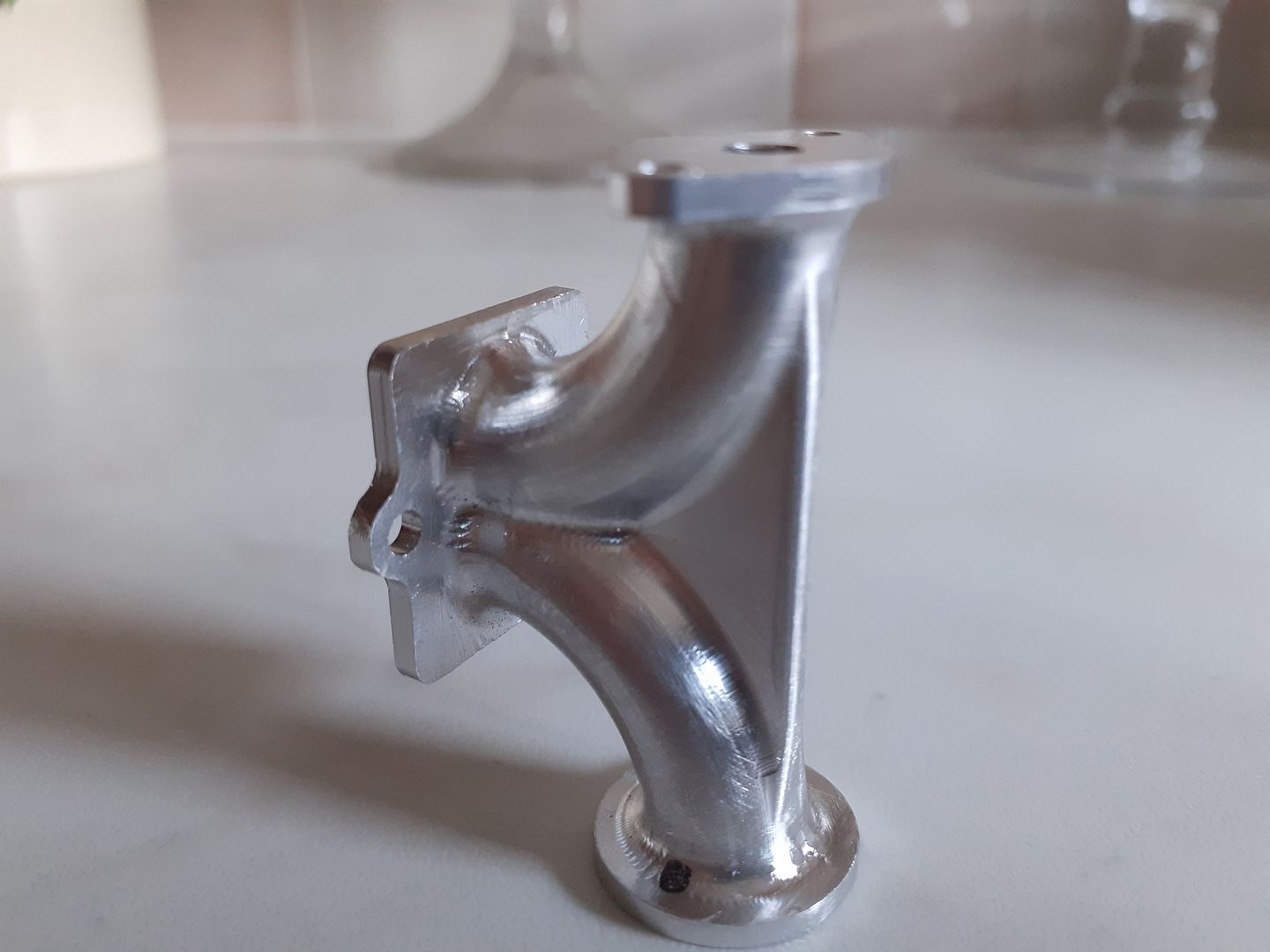
25215 forum posts 3105 photos 1 articles | Thanks Ian, I did toy with the idea of making it as a brass fabrication, it was going to be split down the middle so that I could mill out half round curved passages and then soldered together adding the three separate flanges at the same time. However I really wanted to do it in Aluminium so used Alibre to section my drawn part and then plotted what angle and depth I needed to drill in from to get the holes to meet without going too far. I'm very pleased with the finish, just a few minutes with a needle file to tidy the fillets where the pipe meets the flanges though I could claim I did some very fine TIG welding. I adjusted the Z=axis gib the other day making it slightly looser and now don't have to program in any backlash compensation as before there was obviously a bit of sticktion which was leaving a slight ridge where the 3D path went from up to down.
|
| Ian Johnson 1 | 07/11/2020 19:19:47 |
| 381 forum posts 102 photos | I haven't used backlash compensation yet. On my Z axis I do have a few thou backlash so I was going to tighten things up ready for a bit of 3d milling, but you have made the Z axis looser? How does that work? IanJ |
| JasonB | 07/11/2020 19:37:47 |
25215 forum posts 3105 photos 1 articles | I think mine was a bit too tight to start with and was slightly jerky when jogging down, looks like I have got it about right now. |
| JasonB | 12/11/2020 14:58:04 |
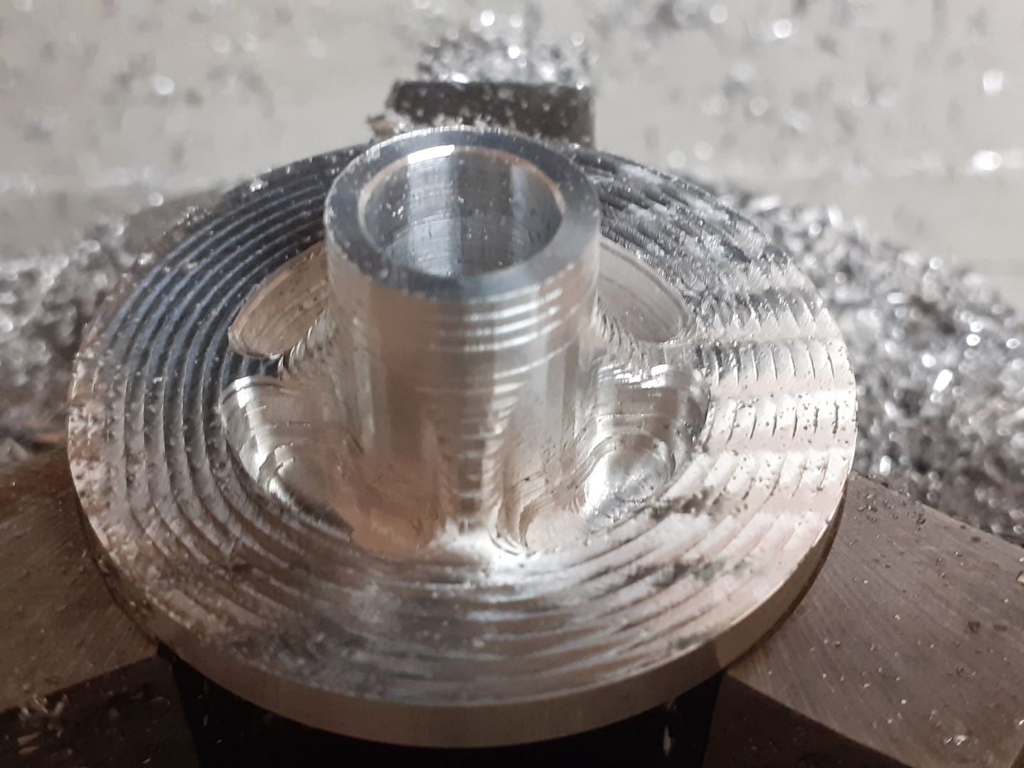
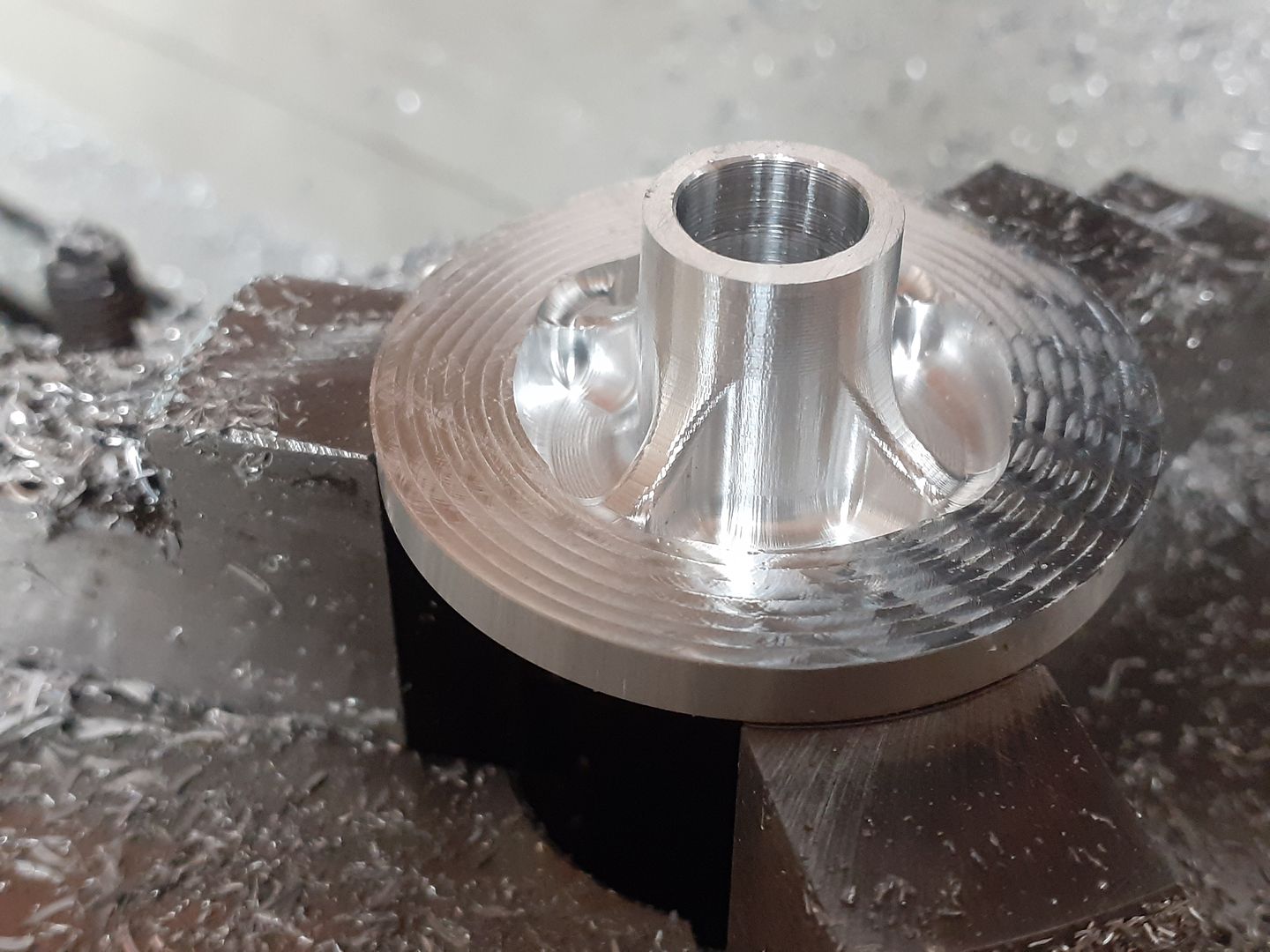
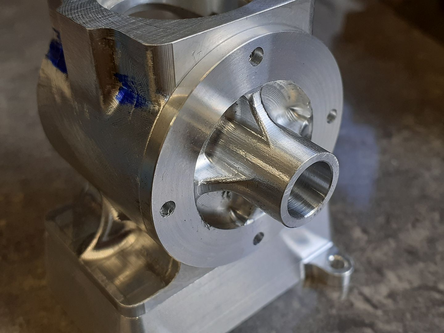
25215 forum posts 3105 photos 1 articles | I had an hour to spare so decided to carve out another casting, this time one of the end plates for the Wall engine, turning of the spigot that locates in the crankcase and boring for the bearing had already been done in the lathe so just the external shape to be done. After adaptive clearing and pocketing with a 4mm 3-flute Carbide cutter for aluminium at 5000rpm, 300mm/min feed, 4mm high cut x 1mm stepover on the adaptive and 1mm x 1mm on the pocket ramping down into the recesses.
Then steep and Shallow while I still can with the boundary set within the inner diameter of the flange, 4mm ball nose 2-flute carbide at 5000rpm, 300mm/min feed 0.3mm stepover.
After that photo I also used the CNC to spot and drill the four 3mm holes. The flange had been left with 0.5mm remaining which I went back to the lathe to turn off.
|
| Ketan Swali | 12/11/2020 16:28:09 |
| 1481 forum posts 149 photos | Posted by JasonB on 07/11/2020 18:43:28:
Thanks Ian, I did toy with the idea of making it as a brass fabrication, it was going to be split down the middle so that I could mill out half round curved passages and then soldered together adding the three separate flanges at the same time. However I really wanted to do it in Aluminium so used Alibre to section my drawn part and then plotted what angle and depth I needed to drill in from to get the holes to meet without going too far. I'm very pleased with the finish, just a few minutes with a needle file to tidy the fillets where the pipe meets the flanges though I could claim I did some very fine TIG welding. I adjusted the Z=axis gib the other day making it slightly looser and now don't have to program in any backlash compensation as before there was obviously a bit of sticktion which was leaving a slight ridge where the 3D path went from up to down.
that looks very close to the edge where the two points meet. Glad you got away with it. Ketan at ARC |
| JasonB | 12/11/2020 16:57:49 |
25215 forum posts 3105 photos 1 articles | It's more than it looks. Due to the web and fillets between web and curved outer there is still some metal to play with. I did use the DRO to get the depths of the drilled holes rather than just the quill feed scale. |
| JasonB | 31/12/2020 19:00:35 |
25215 forum posts 3105 photos 1 articles | A while ago I posted a photo of some engraving cutters that I had bought from Sorotec in Germany and have finally got round to trying them out. Although a bit deeper than your average engraving my need was for some letters to apply to the side of a model to represent the cast on wording that would have been done with pattern makers letters. I found a couple of offcuts of soft bending brass which is a bit stickier to machine than the normal harder brasses used for machining and engraving so a good test for the cutters and with a thickness of 1.1mm a lot deeper than you would normally use them at. To hold the sheet material I soft soldered it onto an off cut of 1/4" brass originally intending to just have a try and then do al the wording from a single piece but as the first letter went well I just squeezed the rest onto two smaller scraps. Taking the 60deg cutter with a 0.5mm flat end and running at 5000rpm and with a modest feed of 60mm/min and ramping down into the work at 2degrees for a max depth per pass of 0.25mm the cutters took it in their stride and seemed to produce a reasonable chip with minimal burrs left on the soft brass so I'm quite pleased with the result. After melting the work from the backing the letters just pushed out with finger pressure and a quick rub on some Emery had them ready for the next step. I have been upto other CNC things some of which can be found in this thread. where I'll post the finished article in the next day or so.
Edited By JasonB on 31/12/2020 19:01:47 |
| Ron Laden | 31/12/2020 20:13:48 |
 2320 forum posts 452 photos | Posted by JasonB on 07/11/2020 16:32:19:
Edited By JasonB on 07/11/2020 16:39:20 I almost missed this and was just about to say it looks very good but that does not do it justice, it is truly excellent and if ever a part machined from solid looked like a casting this is it. Great stuff Jason. |
| Simon Collier | 31/12/2020 20:30:18 |
 525 forum posts 65 photos | Amazing work. How many hours a week do you reckon you spend in the workshop and computer, ie, all ME activities Jason? I have a tremendously productive mate, who can build a standard gauge detailed tender engine in under two years, including boiler naturally, and it is simply because he puts in huge hours. No mystery. |
| JasonB | 01/01/2021 07:01:09 |
25215 forum posts 3105 photos 1 articles | Thanks Ron, I'm pleased with how it turned out too. Simon, probably best I don't add up all the hours |
| JasonB | 19/01/2021 13:26:32 |
25215 forum posts 3105 photos 1 articles | I decided to make a couple of Flywheels from Cast Iron for my Heinrici model, It was a good chance to try out the air coolant setup that I have been meaning to fit for a while. You can see the swarf build up on the ledges during the adaptive cuts as I was not able to manually clear it while taking the various video clips. But if you can bring yourself to watch through to the 5min mark you will see I have finally rigged up some air which is just enough to clear the swarf ahead of the cutter. The first side I stood over the machine clearing swarf more so on the adaptive than the finish but decided I did not want to waste another 3hrs each side. The second side and second flywheel were left unattended except for doing the tool change trusting F360 to have spat out the right code as each side and each flywheel was slightly different and all went well. |
| Ian Johnson 1 | 19/01/2021 22:54:33 |
| 381 forum posts 102 photos | Good stuff Jason, turned out great as usual, I'm getting to like the adaptive machining it doesn't seem to put as much stress on the tool, and your air blower works well, I've got a small 9ltr shhh ultra quiet compressor from Machine Mart, bit expensive but does the job very well and it is really quiet, I have got an air gun to blow the chips away but it just blows them all over the place! So your low pressure set up is something to consider. IanJ |


Please login to post a reply.
Magazine Locator
Want the latest issue of Model Engineer or Model Engineers' Workshop? Use our magazine locator links to find your nearest stockist!
Sign up to our Newsletter
Sign up to our newsletter and get a free digital issue.
You can unsubscribe at anytime. View our privacy policy at www.mortons.co.uk/privacy
Latest Forum Posts
- *Oct 2023: FORUM MIGRATION TIMELINE*
05/10/2023 07:57:11 - Making ER11 collet chuck
05/10/2023 07:56:24 - What did you do today? 2023
05/10/2023 07:25:01 - Orrery
05/10/2023 06:00:41 - Wera hand-tools
05/10/2023 05:47:07 - New member
05/10/2023 04:40:11 - Problems with external pot on at1 vfd
05/10/2023 00:06:32 - Drain plug
04/10/2023 23:36:17 - digi phase converter for 10 machines.....
04/10/2023 23:13:48 - Winter Storage Of Locomotives
04/10/2023 21:02:11 - More Latest Posts...
- View All Topics
Support Our Partners


Shopping Partners
Subscription Offer

Latest "For Sale" Ads
- Reeves** - Rebuilt Royal Scot by Martin Evans
by John Broughton
£300.00 - BRITANNIA 5" GAUGE James Perrier
by Jon Seabright 1
£2,500.00 - Drill Grinder - for restoration
by Nigel Graham 2
£0.00 - WARCO WM18 MILLING MACHINE
by Alex Chudley
£1,200.00 - MYFORD SUPER 7 LATHE
by Alex Chudley
£2,000.00 - More "For Sale" Ads...
Latest "Wanted" Ads
- D1-3 backplate
by Michael Horley
Price Not Specified - fixed steady for a Colchester bantam mark1 800
by George Jervis
Price Not Specified - lbsc pansy
by JACK SIDEBOTHAM
Price Not Specified - Pratt Burnerd multifit chuck key.
by Tim Riome
Price Not Specified - BANDSAW BLADE WELDER
by HUGH
Price Not Specified - More "Wanted" Ads...
Get In Touch!
Do you want to contact the Model Engineer and Model Engineers' Workshop team?
You can contact us by phone, mail or email about the magazines including becoming a contributor, submitting reader's letters or making queries about articles. You can also get in touch about this website, advertising or other general issues.
Click THIS LINK for full contact details.
For subscription issues please see THIS LINK.
Digital Back Issues


Donate

 Register
 Log-in
Model Engineer Magazine
- Percival Marshall
- M.E. History
- LittleLEC
- M.E. Clock

ME Workshop
- An Adcock
- & Shipley
- Horizontal
- Mill

Subscribe Now
- Great savings
- Delivered to your door

Pre-order your copy!
- Delivered to your doorstep!
- Free UK delivery!
All Forum Topics > CNC machines, Home builds, Conversions, ELS, automation, software, etc tools > Further Adventures with the Sieg KX3 & KX1