Forum sponsored by:

Stuart Twin Victoria (Princess Royal) Mill Engine
| Dr_GMJN | 22/06/2021 19:58:15 |
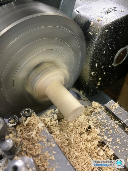
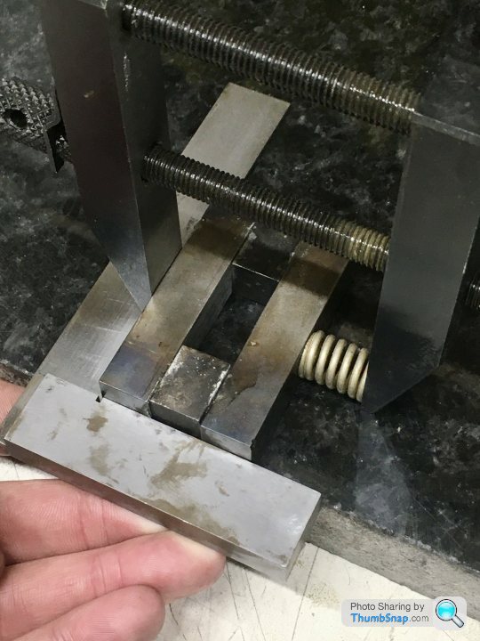
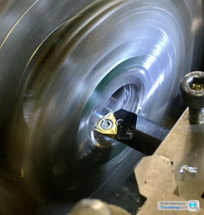
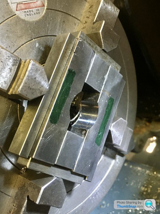
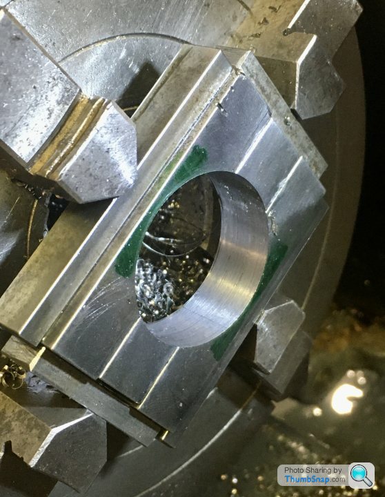
 1602 forum posts | No, I do t have a boring head. Anyway, I made some centre plugs for the cylinders, |
| JasonB | 22/06/2021 20:04:21 |
 25215 forum posts 3105 photos 1 articles | that flux should have been ok so probably not enough heat to get a the metal upto temp. Tin and sweat is the best method |
| Ramon Wilson | 22/06/2021 22:27:00 |
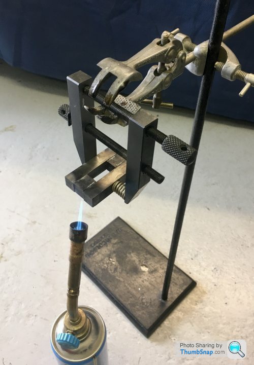
 1655 forum posts 617 photos | How were you holding the pieces together Doc? As Jason says tinning the faces is best but the parts need to be in sufficient contact without being too tight together.
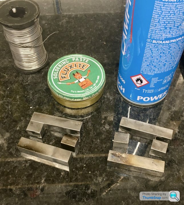
You could try this - a piece of 14-12 swg piano wire bent as a two pronged clamp. Gives just enough pressure to allow the solder to flow. Well flux the parts and put a blob of solder across the joint then heat gently and uniformly until you see the solder flow
Idealy it wants to lay on something non heat absorbent - this is a piece of Skamoflex -perfect for this sort of op.
Edited By Ramon Wilson on 22/06/2021 22:27:36 |
| Dr_GMJN | 22/06/2021 23:30:20 |
1602 forum posts | Thanks both. I was using screw clamps, with flux between the parts, and heating each joint and dabbing with solder until a blob formed, and - sort of - ran into/around the joint. I guess it was too tight a join. I did wonder about some kind in sprung clamp in conjunction with tinned surfaces, but never got them tinned in the first place. Not sure I’ve got any insulating material. I tried to retain heat by doing it on wood, but of course it started to smoke. Maybe an old concrete block? Anyway, I’ll try again tomorrow with piano wire. Cheers. |
| Dr_GMJN | 22/06/2021 23:33:50 |
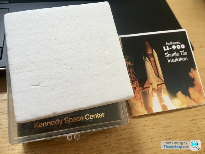
1602 forum posts | In fact thinking about it: I’ve got a section of Space Shuttle re-entry tile material somewhere. That should be a good insulator if it’s big enough. I’ll try and find it tomorrow. |
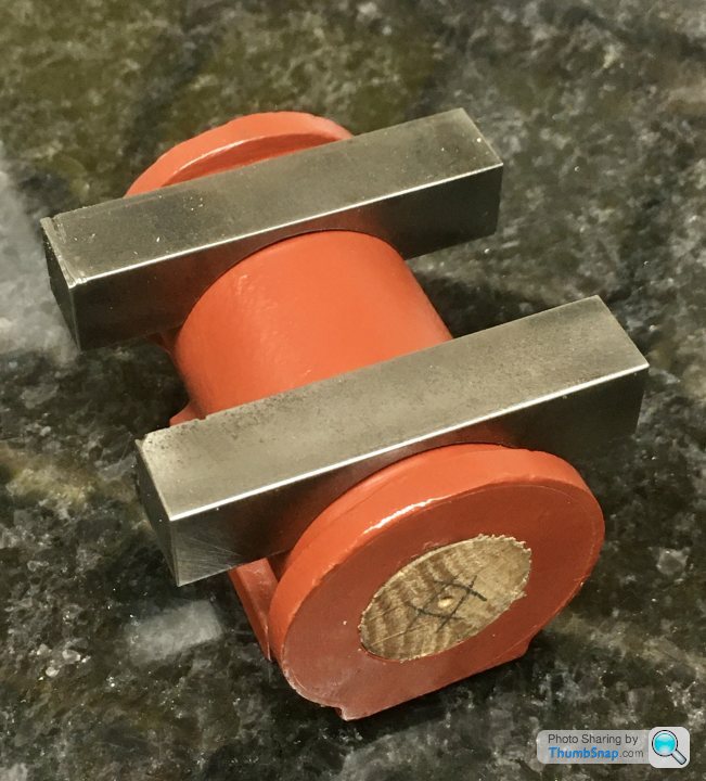
| Dr_GMJN | 23/06/2021 23:16:12 |
1602 forum posts | Soft soldering part 2. As mentioned, I considered using Space Shuttle heat shield insulation to rest the parts on (to retain heat within the parts). I’ve had it for years and it’s pretty useless: |
| JasonB | 24/06/2021 07:07:35 |
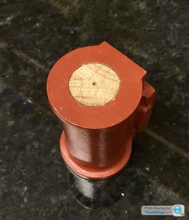
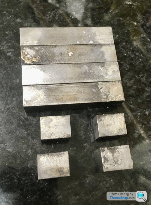
25215 forum posts 3105 photos 1 articles | They turned out OK, I suspect the small burner on your torch did not help with the initial soldering problem. |
| Dr_GMJN | 24/06/2021 07:33:00 |
1602 forum posts | Posted by JasonB on 24/06/2021 07:07:35:
They turned out OK, I suspect the small burner on your torch did not help with the initial soldering problem. Could be. When I tapped the wooden plug into the centres, one assembly cracked apart - and it wasn’t that tight a fit. Had to re-sweat it. Never had an issue with soldering copper plumbing, or electrical stuff, but soldering steel never seems to be very strong the way I do it. |
| Ramon Wilson | 24/06/2021 07:58:14 |
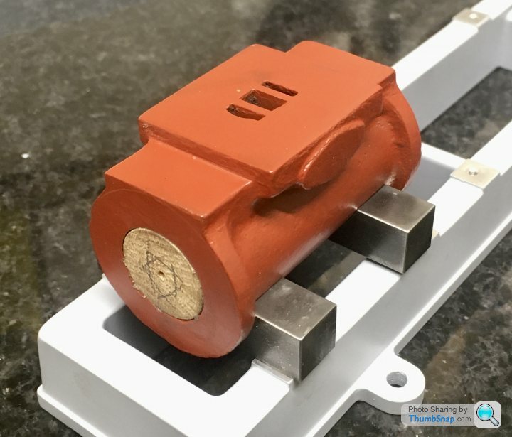
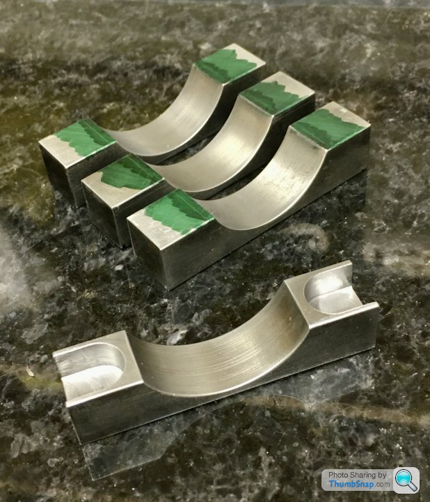
1655 forum posts 617 photos | Nice result Doc Just a point - do you intend to clean that primer off where the JBW is going ? If not it will only be as good a bond as the primer. Hope that's not teachng granny but worth mentioning just in case. Before you JBW them in place file a good, rough, chamfer on the radii - gives an extra surface for the JB to grip onto
|
| Dr_GMJN | 24/06/2021 08:06:29 |
1602 forum posts | Posted by Ramon Wilson on 24/06/2021 07:58:14:
Nice result Doc Just a point - do you intend to clean that primer off where the JBW is going ? If not it will only be as good a bond as the primer. Hope that's not teachng granny but worth mentioning just in case. Before you JBW them in place file a good, rough, chamfer on the radii - gives an extra surface for the JB to grip onto
Thanks Ramon. Intention is to use a sanding cylinder or burr in the dremel to roughen up the mating surfaces on the cylinders and feet. |
| JasonB | 24/06/2021 08:33:25 |
25215 forum posts 3105 photos 1 articles | There is a lot more bulk in those blocks of metal than thin walled copper tube so it will take a lot longer to get the whole of the metal upto temp with that small burner rather than just melting the solder onto the surface. |
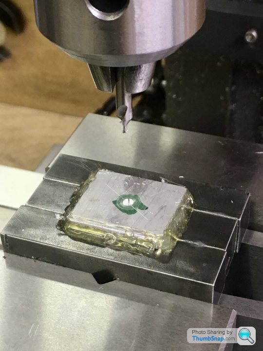
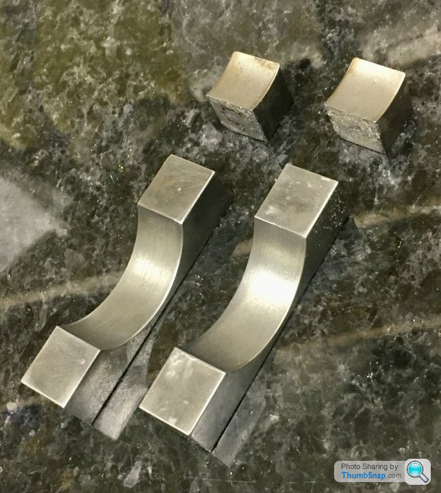
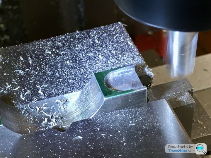
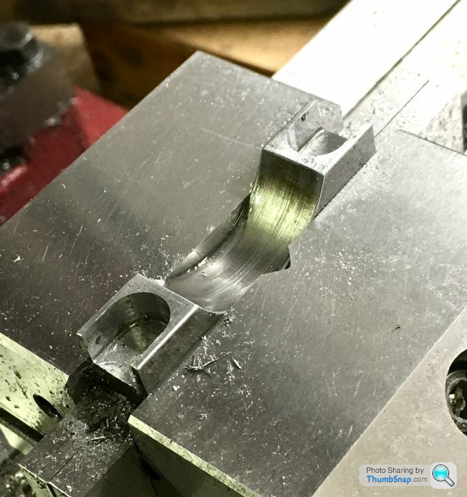
| Dr_GMJN | 24/06/2021 22:05:54 |
1602 forum posts | Carried on machining the other two feet, which was straightforward, then marked out for the pockets, which I did with a slot drill. I marked the extents of the rads w.r.t. the edges of the arc cut-out: |
| JasonB | 25/06/2021 07:06:42 |
25215 forum posts 3105 photos 1 articles | Probably overthinking again or maybe underthinking. You need to remember it's a casting you are trying to replicate and that would never have had micron accuracy. |
| Dr_GMJN | 25/06/2021 07:57:16 |
1602 forum posts | Posted by JasonB on 25/06/2021 07:06:42:
Probably overthinking again or maybe underthinking. You need to remember it's a casting you are trying to replicate and that would never have had micron accuracy. Understand the concept of it looking like a casting, just that there’s hardly any wiggle room at all laterally before the bolt/nut points would hit the inside of the pocket’s vertical wall. The longitudinal position of the holes is easy to get perfect simply by making a flat spacer to fit between the foot blocks as a jig. Anyway, it’s probably been done hundreds of times in the past, so there we go. I’d rather ask the question than have to do re-work or make some kind of compromise. Thanks. |
| JasonB | 25/06/2021 08:14:09 |
25215 forum posts 3105 photos 1 articles | You could always put a shallow 1/16" hole in the underside of the cylinder and a matching one in the middle of the feet which would help locate them using a pin when gluing up.
|
| Dr_GMJN | 25/06/2021 08:27:16 |
1602 forum posts | Posted by JasonB on 25/06/2021 08:14:09:
You could always put a shallow 1/16" hole in the underside of the cylinder and a matching one in the middle of the feet which would help locate them using a pin when gluing up.
I’m ok with the location onto the outside of the cylinder, but the final position of the axis isn’t defined because they’re not bored yet. That’s really the issue, because if they were bored, I could easily line everything up on the mill bed and clamp in place while the JBWeld sets. Then d&t for good measure. basically my assumption is that the bored axis won’t end up being concentric with the outside of the castings, therefore there will be some lateral error. I have no idea how much, but if it’s more than about 1.5 mm it might be an issue in terms of fastener alignment. |
| Ramon Wilson | 25/06/2021 09:25:42 |
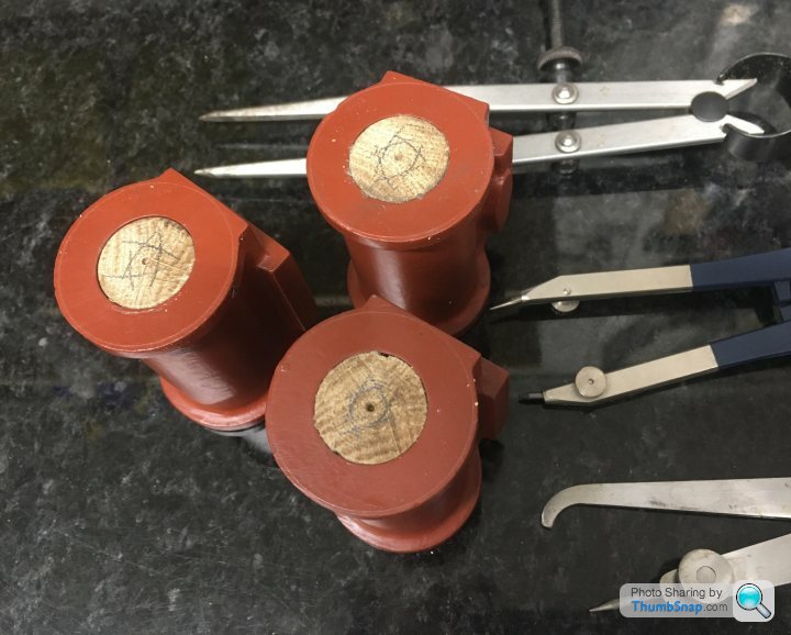
1655 forum posts 617 photos | Hi Doc, I think you are jumping ahead of the game again by making the feet to finished dimension before you fit them to the cylinder or, to put it another way your cylinder dimensions are now going to be defined by the feet. As Jason rightly says in reality the cast feet would not be symetrical and in all probability, nice as it looks, have neatly milled pockets to surround the nuts. (Think of the type of spanner required if so) Were it me I would mill those feet to finished dimensions - and relative to the finished bore - once securely JB'd in place and also do away with those pockets. A more likely prototypical design would be for the top faces to be slightly tapered downwards in an outwards direction and the nuts seating on inserted but protruding level pads - a little extra work but far more in keeping to a prototype.
Something on the lines of this perhaps?
Just a thought - hope it helps Ramon |
| Dr_GMJN | 25/06/2021 10:11:00 |
1602 forum posts | Posted by Ramon Wilson on 25/06/2021 09:25:42:
Hi Doc, I think you are jumping ahead of the game again by making the feet to finished dimension before you fit them to the cylinder or, to put it another way your cylinder dimensions are now going to be defined by the feet. As Jason rightly says in reality the cast feet would not be symetrical and in all probability, nice as it looks, have neatly milled pockets to surround the nuts. (Think of the type of spanner required if so) Were it me I would mill those feet to finished dimensions - and relative to the finished bore - once securely JB'd in place and also do away with those pockets. A more likely prototypical design would be for the top faces to be slightly tapered downwards in an outwards direction and the nuts seating on inserted but protruding level pads - a little extra work but far more in keeping to a prototype.
Something on the lines of this perhaps?
Just a thought - hope it helps Ramon Thanks Ramon. I was really wanting to stick to the original geometry, purely for the sake of proving to myself I can build parts like this from plans and stock material. I don't think the 10V had anything like that. Must admit I'd assumed that by "machining" when in place (i.e. treating as one casting), you guys primarily meant the flats on the base and the fastener holes, rather than the overall form of the feet. I don't think - for the plan parts - that it's possible to machine the pockets and chamfers once assembled to the main casting due to clearance issues. The pocket ends would certainly be extremely close to the cylinder sides, and the cylinder end flanges would obstruct machining of the chamfers. Thinking more about it, I've got the centred plugs in the cylinder bores, and these effectively will be the axes of the finished bores, because they are what I'm aligning the boring bar with. So there must be a way of setting the cylinders on the feet with these as datums while the JB Weld sets. Not quite figured out how yet, but it should easily get me within the necessary tolerance. Cheers.
|
| JasonB | 25/06/2021 11:36:41 |
25215 forum posts 3105 photos 1 articles | If you mark a ctr line on a flat surface, the feet and then stand them on it with your end to end spacer and hot glue or clamp them in place so ctr lines are lined up you can then apply your JBW and put the cylinder in place then use a square to check your pop marks on the plugs are sitting vertically over the ctr line you should not be far out. If your nut clearances are as tight as you say then think how you will tighten them, I you stick with that design may need one size smaller hex nuts or hold nut in place and use screws up from the underside through claearence holes if you can't get a spanner in. Also worth noting that like me ramon tends to run a Dremel over the surfaces to give them a bit of texture and also knock off all the external corners, makes the difference between a painted "barstock" engine and one made from "castings" |
| Dr_GMJN | 25/06/2021 14:03:52 |
1602 forum posts | Posted by JasonB on 25/06/2021 11:36:41:
If you mark a ctr line on a flat surface, the feet and then stand them on it with your end to end spacer and hot glue or clamp them in place so ctr lines are lined up you can then apply your JBW and put the cylinder in place then use a square to check your pop marks on the plugs are sitting vertically over the ctr line you should not be far out. If your nut clearances are as tight as you say then think how you will tighten them, I you stick with that design may need one size smaller hex nuts or hold nut in place and use screws up from the underside through claearence holes if you can't get a spanner in. Also worth noting that like me ramon tends to run a Dremel over the surfaces to give them a bit of texture and also knock off all the external corners, makes the difference between a painted "barstock" engine and one made from "castings"
I was thinking put a bit of aluminium plate on the mill bed, co-ordinate d&t four holes to match the bed, then drill the feet blocks close clearance 4BA, at the same time I'm milling the pockets. Might as well mill them to length too. I can also spot two small holes on the plate, and scribe a centreline - as you say. Then bolt the feet in place and fettle everything so the cylinder seats nicely, and fits laterally using the square to check alignment (within a couple of mm). The height doesn't matter so much because that will be achieved by milling the foot pads later on. When I'm placing the cylinder, I'll have to check that the valve plate is horizontal, and will clean up once fixed. I suppose I'll have to use the scribing block/surface gauge for this. Might invest in a vernier height gauge at some point, which would probably be easier to set to a precise height for scribing/checking. So I suppose I'll end up doing half it like a whole casting, and half like an assembly. BTW a 7/32" socket fits in the pocket, and matches the bolts (which will be nuts on assembly), so tightening shouldn't be an issue. Thanks. |


Please login to post a reply.
Magazine Locator
Want the latest issue of Model Engineer or Model Engineers' Workshop? Use our magazine locator links to find your nearest stockist!
Sign up to our Newsletter
Sign up to our newsletter and get a free digital issue.
You can unsubscribe at anytime. View our privacy policy at www.mortons.co.uk/privacy
Latest Forum Posts
- hemingway ball turner
04/07/2025 14:40:26 - *Oct 2023: FORUM MIGRATION TIMELINE*
05/10/2023 07:57:11 - Making ER11 collet chuck
05/10/2023 07:56:24 - What did you do today? 2023
05/10/2023 07:25:01 - Orrery
05/10/2023 06:00:41 - Wera hand-tools
05/10/2023 05:47:07 - New member
05/10/2023 04:40:11 - Problems with external pot on at1 vfd
05/10/2023 00:06:32 - Drain plug
04/10/2023 23:36:17 - digi phase converter for 10 machines.....
04/10/2023 23:13:48 - More Latest Posts...
- View All Topics
Support Our Partners


Shopping Partners
Subscription Offer

Latest "For Sale" Ads
- Reeves** - Rebuilt Royal Scot by Martin Evans
by John Broughton
£300.00 - BRITANNIA 5" GAUGE James Perrier
by Jon Seabright 1
£2,500.00 - Drill Grinder - for restoration
by Nigel Graham 2
£0.00 - WARCO WM18 MILLING MACHINE
by Alex Chudley
£1,200.00 - MYFORD SUPER 7 LATHE
by Alex Chudley
£2,000.00 - More "For Sale" Ads...
Latest "Wanted" Ads
- D1-3 backplate
by Michael Horley
Price Not Specified - fixed steady for a Colchester bantam mark1 800
by George Jervis
Price Not Specified - lbsc pansy
by JACK SIDEBOTHAM
Price Not Specified - Pratt Burnerd multifit chuck key.
by Tim Riome
Price Not Specified - BANDSAW BLADE WELDER
by HUGH
Price Not Specified - More "Wanted" Ads...
Get In Touch!
Do you want to contact the Model Engineer and Model Engineers' Workshop team?
You can contact us by phone, mail or email about the magazines including becoming a contributor, submitting reader's letters or making queries about articles. You can also get in touch about this website, advertising or other general issues.
Click THIS LINK for full contact details.
For subscription issues please see THIS LINK.
Digital Back Issues


Donate

 Register
 Log-in
Model Engineer Magazine
- Percival Marshall
- M.E. History
- LittleLEC
- M.E. Clock

ME Workshop
- An Adcock
- & Shipley
- Horizontal
- Mill

Subscribe Now
- Great savings
- Delivered to your door

Pre-order your copy!
- Delivered to your doorstep!
- Free UK delivery!
All Forum Topics > Work In Progress and completed items > Stuart Twin Victoria (Princess Royal) Mill Engine