Forum sponsored by:

Stuart Twin Victoria (Princess Royal) Mill Engine
| Dr_GMJN | 19/06/2021 19:09:23 |
 1602 forum posts | Clive, this is the “Princess Royal” version of the Twin Victoria, which has quite a few modifications to the standard model (as explained in the first post). Cheers. |
| Clive Brown 1 | 19/06/2021 19:28:17 |
| 1050 forum posts 56 photos | Posted by Dr_GMJN on 19/06/2021 19:09:23:
Clive, this is the “Princess Royal” version of the Twin Victoria, which has quite a few modifications to the standard model (as explained in the first post). Cheers. Thanks, must read complete threads in future before jumping in. Even if it means changing the habits of a lifetime |
| Dr_GMJN | 19/06/2021 19:38:22 |
1602 forum posts | Posted by Clive Brown 1 on 19/06/2021 19:28:17:
Posted by Dr_GMJN on 19/06/2021 19:09:23:
Clive, this is the “Princess Royal” version of the Twin Victoria, which has quite a few modifications to the standard model (as explained in the first post). Cheers. Thanks, must read complete threads in future before jumping in. Even if it means changing the habits of a lifetime Nothing much apart from questions from me for the first 7 pages I’m afraid… |
| Dr_GMJN | 19/06/2021 21:07:53 |
1602 forum posts | Posted by JasonB on 19/06/2021 13:07:29:
That's it. The intermittant cut should not be an issue and if you had the "spacers" a little closer together in your sketch then the final cuts will be constant. A loose packer at either end will spread the load rather than push against the central soldered in packers, infacct arranged that way you could use superglue rather than solder as then it is only a case of stopping the bits sliding about when initially clamping.
Actually I was thinking more of the horizontal beams being weak towards the final cuts. I could also use spreaders on the upper and lower bars to spread the clamp force there. |
| Dr_GMJN | 21/06/2021 12:33:48 |
1602 forum posts | So I've been pondering the workflow for the cylinders again. I know I've asked about this before, but it's a bit confusing because there are a lot of things that need to be assembled and aligned, and I don't want to end up with cylinder feet that have to be noticeably asymmetric to correct things: a) The cylinder axis needs to be aligned with the bed, vertically, horizontally and longitudinally. b) The valve face needs to be horizontal and flat (and there's hardly any machining allowance on it). c) The feet have to be fixed to the cylinder in such a way that their lower spigots fit snugly between the beds ( I assume), aligned with the existing holes in the bed, and also make the cylinder axis conform with a). Current thoughts are: 1) Make the upper features of the feet exactly to drawing (width, length, circular cylinder seatings, milled bolt recesses and drilled mounting holes, tapered sides drilled, and drilled tapping sized holes for cylinder bolts), but leave the undersides flat, ie no spigot features. 2) Plug the cylinder bore with centre drilled wooden plugs both ends. Check that the o/ds of the cast flanges are more or less concentric with the plug o/ds (this will make the fettling for fitting the cylinder cladding easier). 3) Temporarily attach feet to bed, then add the cylinder on top. Confirm that the cylinder axis is aligned with the bed (using the mill DROs, in conjunction with the centre drillings and perhaps a rod through the holes), and - very carefully - ensure that the roughly flatted cast valve face is also nominally horizontal. Then apply JB Weld and allow to cure. 4) Once set, drill all the way through the cylinder to tapping size using the feet holes as a jig, open up the holes in the feet to be clearance, tap the cylinder, and add the bolts - coated with JB Weld. Once set, remove any bolt ends protruding into the cylinder with a file. 5) Setup the cylinder on the lathe cross-slide, sitting on its feet and again using the centred wooden plugs as an alignment guide, bore the cylinders. 6) Fly-cut the piston-rod ends of the cylinders in the same setup. 7) Transfer the machined cylinder to the mill, and setup on it's feet and mill the valve face, which in theory should be nominally flat, as per 3) 8) Turn upside down so they cylinder sits on the valve face, align longitudinally, and machine the feet undersides to be a snug fit in the beds. That should get me in the ballpark of them being right by default, but I'm a bit concerned that the side-to-side alignment will have no adjustment. I'm assuming that the lower spigots on the feet are intended to be a fit on the beds (otherwise what's the point of them?). Obviously any horizontal drop or rise of the axis can be corrected with shims or more machining if necessary, but in theory I guess it should be right. I assume as per usual I'm over-thinking this, so any comments much appreciated! |
| JasonB | 21/06/2021 13:14:52 |
 25215 forum posts 3105 photos 1 articles | I think I would only do the arc, 2 "D" shapes and the angled cuts on the feet and get them fixed in position, leave trimming to O/A length, the stepped bottom and the 4 fixing holes until the cylinder has been bored then you can pick up it's position and get the heights and hole positions set from there. Basically create the "casting" first them machine it I don't think the step on the bottom is to provide sideways location as at 1 5/16" it's a lot narrower than the gap between the bedplate casting which is about 1.400". Most likely there to stop the feet becoming too flexible as there would be little material left if they were just flat bottomed. |
| Ramon Wilson | 21/06/2021 14:48:32 |
 1655 forum posts 617 photos | 'Yep' agree with Jason here Doc G, get the feet (over thick) well established to the casting before machining anything
Said it before but it's worth saying again - personally I would then do the bore(s) first then bring every thing to it - both ends on the lathe held on a mandrel, valve face and feet height on the mill - preferably held on a mandrel or with one face bolted to a good angle plate - all faces, depending on the accuracy of the mandrel true to the bore position. This is a much better way of achieving surfaces true to the bore rather than the bore true to the surfaces much better accuracy and with minimum set ups. All the above ops were done on this Mc Onie cylinder as suggested Hope that helps some Doc Ramon |
| Dr_GMJN | 21/06/2021 16:24:34 |
1602 forum posts | Jason, Ramon, Thanks both - I know we've been here before, but I'm still not 100%, and this time it's for real. I think basically what I've suggested is what you're suggesting, ie fit the feet to the cylinder, then machine the bore, faces, valve face and finally the feet (or the feet then the face). The methods of doing it are slightly different though. The reason I suggested temporarily fitting the feet to the bed, then confirming the cylinder was square on them before JB welding, was I thought it would at least eliminate the alignment being grossly out, which in turn would mean asymmetric feet somewhere or other. I take Jason's point about leaving the feet overall length until later, and also the spigot not being a tight fit. I think I've confused myself by drawing my own beds, and assuming they were a snug fit. no problem there though, it simplifies things a bit. So that leaves me with a few unknowns - or at least things to confirm: 1) Is the centre-marked wooden plug method sound for initial setting of the cylinder on the lather for boring? Thinking put two centres in the head and tail stock and pack/align the cylinder to those? Might use the vertical slide and lock the gibs. 2) I'm assuming for milling I clamp the mandrel to the angle plate, check it's level, then datum off it by touching with the cutter on the top to get it's axis position, then clamp the cylinder to it? Then offset for the feet/valve face cuts assuming the mandrel/cylinder axes are coincident? 3) Assuming 2 is right, I'd want to mill the valve face first, because I've hardly got any machining allowance there and would want to double-check all around with a height gauge that I'm taking a more or less equal amount off, and not going to crash into the cast inlet port pad. Could do a rough vertical measurement on the feet at the same time as a sanity check But then how do I spin the cylinder to get the feet uppermost, with the valve face exactly parallel with the bed? Clamp the machined face direct to the bed and somehow re-align the cylinder axis? Sorry for the questions, but must admit I'm confused about the alignment details rather than the overall concept of what to do. Thanks.
|
| Ramon Wilson | 21/06/2021 17:31:10 |
1655 forum posts 617 photos | Hi Doc, I can see your concern but I'm sure you can overcome it Okay, lets assume you had bought cylindercastings with integral feet - the first thing would be to create a datum and the largest area would be that covered by the feet . This could be filed or machined to give a reasonable flat surface (but not as yet finished) from which to put in your bore. You would use this face to set up either on an angle plate on the face plate or better still on an angleplate/vertical slide on the cross slide for between centres boring. To my mind you need to create this situation before anything else ie fit the feet firmly in situ with JBW and let it really set before further machining to create that initial datum. If the hole as cast is reasonable then using plugs to get a centre relative to the outer circumference of the cylinder ends is fine but bear in mind getting the bore central to the casting is more important than getting the 'as cast' bore central to the boring bar. Once that bore is finished you now have a datum from which all other faces can be made true. The ends are faced (not fly cut) on the lathe on a mandrel. Mount the mandrel on the mill as suggested and centre the spindle across its diameter. Mount the cylinder as fair as you can with the valve face underneath - still untouched - level with the table. Use a parallel to near fill the space and eye the gap - you'll be surprised how close you can get and certainly close enough here. Bring the feet to a true dimension to the bore - you would need to take care that when JB Welding them in place you ensure a reasonable degree of symmetry to prevent odd thicknesses - and you now have the bottom face true to the bore and at the right height dimension. Remove from the mandrel and clamp to the table (or bolt to a sub plate using the mounting holes in the feet) and take the final cut over the valve face to finish size. Whether you chose to use a fly cutter or small end mill to do this op is up to you but a 6mm cutter over lapped say 4-5 mm will ensure you have a 'flat' face albeit not so pretty. If you find you don't have enough to clean up to size then you could mill it lower and fit (JBW) a false face and re-mill(best) or change the thickness of the valve chest and possibly the valve to suit (not so best) Hope that helps - main thing is to 'have it right' in your own mind before making those first cuts
Ramon
Edited By Ramon Wilson on 21/06/2021 17:35:24 |
| JasonB | 21/06/2021 18:29:05 |
25215 forum posts 3105 photos 1 articles | Another option to plugging the ends is to stick a thin bit of scrap sheet to the ends with hot melt glue, I use this quite often when there is a hole where I want to put a mark such as the ecc strap on the Victoria.
|
| JasonB | 21/06/2021 18:48:33 |
25215 forum posts 3105 photos 1 articles | Just to add, if you are not familiar with the usual way to find the ctr of the casting then striking 4 arcs of aprox half dia will get you close and you them place your ctr mark in the middle of the arcs. If you don't have odd leg callipers then find a bit of bar aprox half flange dia and use that to scribe 4 lines with bar and cylinder on a flat surface. If you have ascribing block or height gauge that can be used too do the same sort of thing.
Edited By JasonB on 21/06/2021 18:50:35 |
| Ramon Wilson | 21/06/2021 21:32:43 |
1655 forum posts 617 photos | Posted by JasonB on 21/06/2021 18:29:05:
Another option to plugging the ends is to stick a thin bit of scrap sheet to the ends with hot melt glue, I use this quite often when there is a hole where I want to put a mark such as the ecc strap on the Victoria.
That's a good tip Jason, well worth keeping in the memory bank |
| Dr_GMJN | 21/06/2021 21:53:04 |
1602 forum posts | Thanks both - is aluminium ok to make the mandrel? Also, I think Jason mentioned fly-cutting the piston-rod end of the cylinder in the lathe, in the same setup as for the boring? |
| Ramon Wilson | 21/06/2021 22:47:08 |
1655 forum posts 617 photos | In this instance I don't see why not Doc, but I would advise never to make an Ali mandrel to hold an Ali part, the chances of pick up and seizing are potentially far too great. Why would you want to fly cut the ends when it can be held on a freshly turned mandrel and both ends faced correctly, perfectly square to the bore? Not saying flycutting it it can't or shouldn't be done just not quite sure I see the reasoning behind doing it that way. Been re -machining a commercial glow motor crankcase today. One mandrel made to suit the main crankase bore and all ops done from that - much the same really
Edited By Ramon Wilson on 21/06/2021 22:48:36 |
| JasonB | 22/06/2021 07:23:43 |
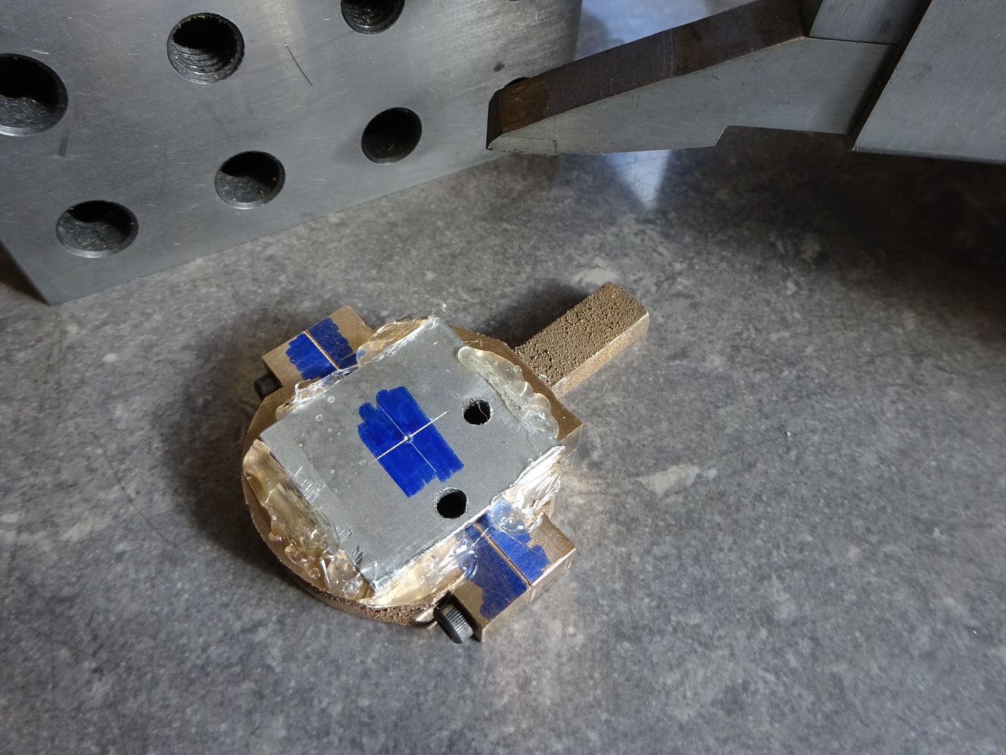
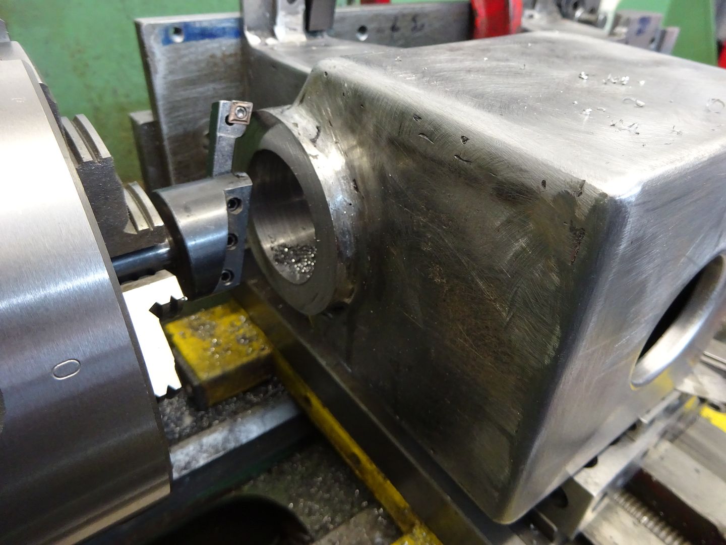
25215 forum posts 3105 photos 1 articles | Probably comes from me doing a few larger bores where the casting is too big to turn so the end of the cylinder was flycut at the same setting as that for boring. Bon critical end can be done in other ways such as with cylinder clamped vertically to mill table with flycut end at the bottom so should be true to opposite end. I also tend to do this sort of size cylinder in the 4-jaw so again easy to turn the critical end while it's still in the chuck. Other reason is it saves making a mandrel and with some of my bores 5-6" long and close to 2" dia thats a big bit of metal. This one was flycut after boring
Don't think I would have enjoyed turning this on a mandrel even if I had a lathe big enough to swing it 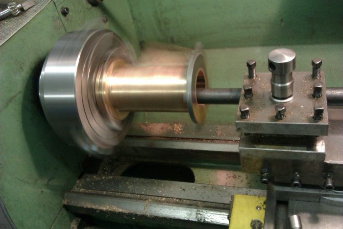 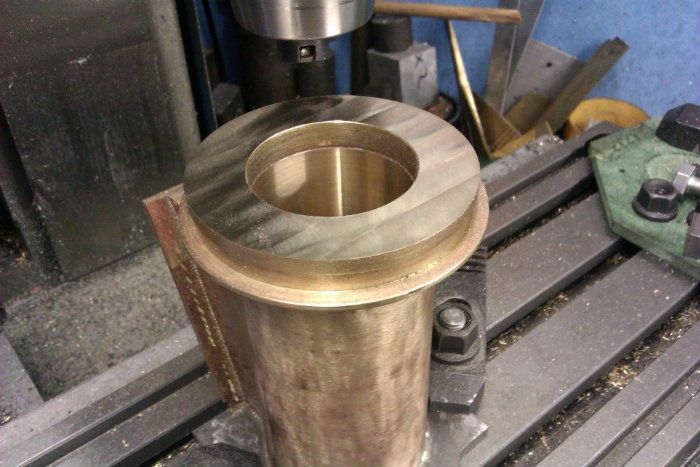 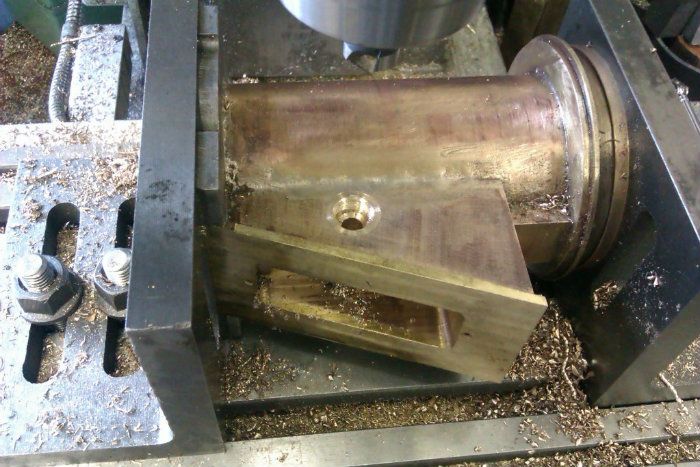 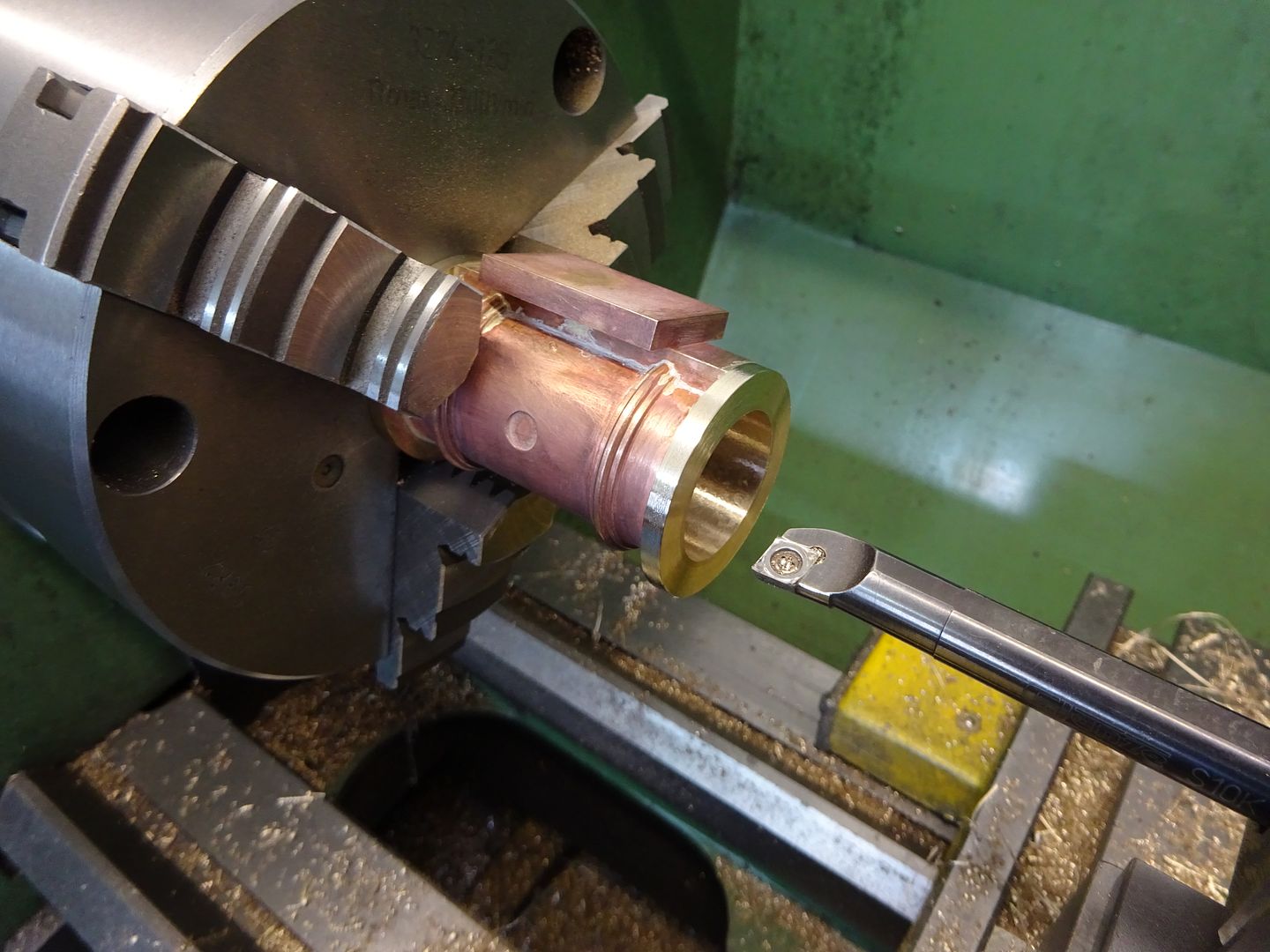 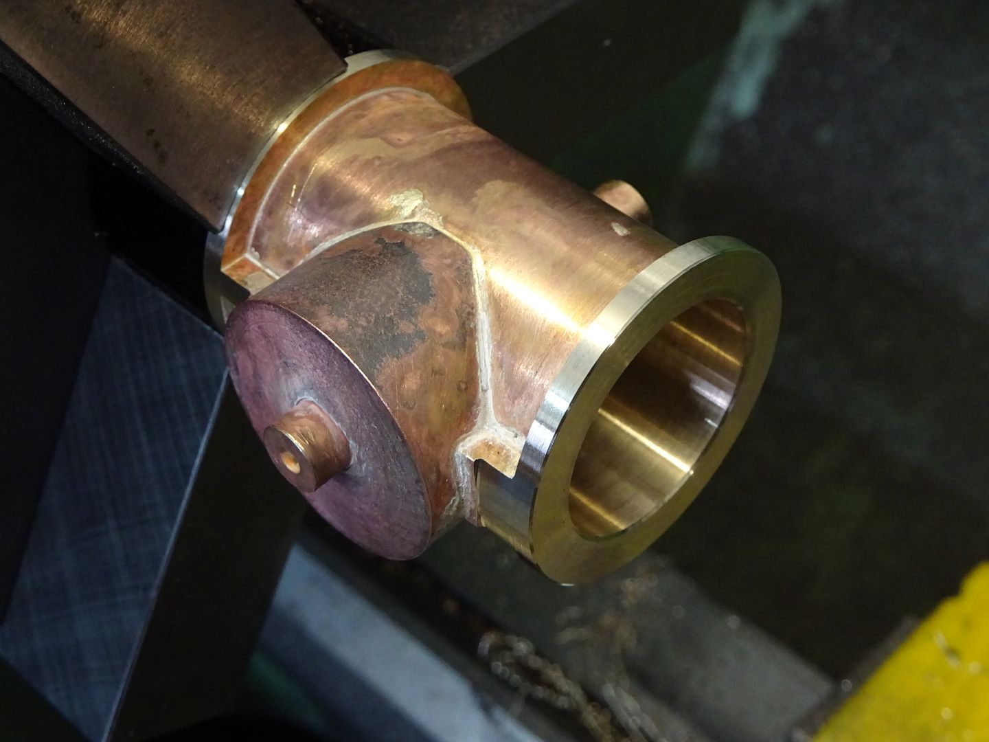
|
| Dr_GMJN | 22/06/2021 08:18:56 |
1602 forum posts | OK thanks guys - I can now get on with the cylinders. I think the main hurdle - or at least new process - for me to get right is the between centres boring, which I'm keen to try. First job though is to make the feet. |
| JasonB | 22/06/2021 08:28:05 |
25215 forum posts 3105 photos 1 articles | Talking of the feet, I just realised the thicker stepped bottom gives enough depth for the drain cock holes, if they were flat right across there would not be much metal to get a decent depth of thread into. I see TC suggests either option for doing the flanges and suspect a lot of cylinders have had them turned at the same setting as boring as all the books on making the engines that use this cylinder casting do it that way |
| Ramon Wilson | 22/06/2021 08:36:11 |
1655 forum posts 617 photos | Yes Jason, quite see your point - as usual it's 'horses for courses' and I had overlooked that you do tackle much larger parts than I usually do - looks at times you are pushing your lathe and mill capacity to the limit with great results The ability to change parts or remove and replace is definitely a bonus when using mandrels as you say however. Looking forwards to more progress Doc
Ramon
|
| Dr_GMJN | 22/06/2021 13:42:35 |
1602 forum posts | Posted by JasonB on 22/06/2021 08:28:05:
Talking of the feet, I just realised the thicker stepped bottom gives enough depth for the drain cock holes, if they were flat right across there would not be much metal to get a decent depth of thread into. I see TC suggests either option for doing the flanges and suspect a lot of cylinders have had them turned at the same setting as boring as all the books on making the engines that use this cylinder casting do it that way I think if the feet were cut straight across, the cut would intersect the circle, and you’d have two halves rather than one foot (see 2D CAD a few posts back). I’ll have to double check that, because the remaining material still looks thin. That’s why I was asking about clamping the three bits in the Chuck - by the time the circle is bored out, it looks to me like the pieces could bend under the Chuck jaw loads. A spreader would help with this, similar to what you had at the sides of the three piece assembly. |
| JasonB | 22/06/2021 14:00:52 |
25215 forum posts 3105 photos 1 articles | There won't be much meat, maybe 2mm so would not hurt to slip a bit of packing in each side. I don't think you have a boring head otherwise it could be done in the mill and the vice jaws would grip along the whole length rather than just a point load on the thinnest part, you could even get away without soldering with that setup. |


Please login to post a reply.
Magazine Locator
Want the latest issue of Model Engineer or Model Engineers' Workshop? Use our magazine locator links to find your nearest stockist!
Sign up to our Newsletter
Sign up to our newsletter and get a free digital issue.
You can unsubscribe at anytime. View our privacy policy at www.mortons.co.uk/privacy
Latest Forum Posts
- *Oct 2023: FORUM MIGRATION TIMELINE*
05/10/2023 07:57:11 - Making ER11 collet chuck
05/10/2023 07:56:24 - What did you do today? 2023
05/10/2023 07:25:01 - Orrery
05/10/2023 06:00:41 - Wera hand-tools
05/10/2023 05:47:07 - New member
05/10/2023 04:40:11 - Problems with external pot on at1 vfd
05/10/2023 00:06:32 - Drain plug
04/10/2023 23:36:17 - digi phase converter for 10 machines.....
04/10/2023 23:13:48 - Winter Storage Of Locomotives
04/10/2023 21:02:11 - More Latest Posts...
- View All Topics
Support Our Partners


Shopping Partners
Subscription Offer

Latest "For Sale" Ads
- Reeves** - Rebuilt Royal Scot by Martin Evans
by John Broughton
£300.00 - BRITANNIA 5" GAUGE James Perrier
by Jon Seabright 1
£2,500.00 - Drill Grinder - for restoration
by Nigel Graham 2
£0.00 - WARCO WM18 MILLING MACHINE
by Alex Chudley
£1,200.00 - MYFORD SUPER 7 LATHE
by Alex Chudley
£2,000.00 - More "For Sale" Ads...
Latest "Wanted" Ads
- D1-3 backplate
by Michael Horley
Price Not Specified - fixed steady for a Colchester bantam mark1 800
by George Jervis
Price Not Specified - lbsc pansy
by JACK SIDEBOTHAM
Price Not Specified - Pratt Burnerd multifit chuck key.
by Tim Riome
Price Not Specified - BANDSAW BLADE WELDER
by HUGH
Price Not Specified - More "Wanted" Ads...
Get In Touch!
Do you want to contact the Model Engineer and Model Engineers' Workshop team?
You can contact us by phone, mail or email about the magazines including becoming a contributor, submitting reader's letters or making queries about articles. You can also get in touch about this website, advertising or other general issues.
Click THIS LINK for full contact details.
For subscription issues please see THIS LINK.
Digital Back Issues


Donate

 Register
 Log-in
Model Engineer Magazine
- Percival Marshall
- M.E. History
- LittleLEC
- M.E. Clock

ME Workshop
- An Adcock
- & Shipley
- Horizontal
- Mill

Subscribe Now
- Great savings
- Delivered to your door

Pre-order your copy!
- Delivered to your doorstep!
- Free UK delivery!
All Forum Topics > Work In Progress and completed items > Stuart Twin Victoria (Princess Royal) Mill Engine