Forum sponsored by:

Stuart 10V Build Log - Complete Beginner...
| JasonB | 27/06/2020 15:27:25 |
 25215 forum posts 3105 photos 1 articles | Coming together nicely, this is where the DRO comes into it's own and spotting through a thing of the past. |
| Dr_GMJN | 27/06/2020 17:06:35 |
 1602 forum posts | Posted by JasonB on 27/06/2020 15:27:25:
Coming together nicely, this is where the DRO comes into it's own and spotting through a thing of the past. Thanks. Yes, slow, but - sort of sure. My lathe work is noticeably worse than the milled stuff in terms of accuracy. I really need to get some DRO’s for the ML7, but all the methods I’ve seen for attaching them look a bit naff and fragile. |
| Dr_GMJN | 28/06/2020 08:34:29 |
1602 forum posts | The last casting to be machined is the flywheel. There are several methods suggested in books or online. The simplest seems to be drill and ream the hole and mount on a mandrel. Im wondering if it would be better to bore the hole to be a tight fit on the supplied shaft (rather than ream and get a running fit), and then drill the grub screw hole and mount to some spare crankshaft rod using the screw? my thinking is that this is how the wheel will be fitted, so why not machine it as such and account for any slight deflection caused by the screw? would boring the hole possibly not give a good enough fit in terms of possible taper? suggestions welcome as always. Thanks. |
| Dr_GMJN | 28/06/2020 08:58:06 |
1602 forum posts | The other thing is - is it best to drill the cylinder drain tap holes before lapping? And what is the suggested size for the hole for these that breaks through into the cylinder? Presumably the threaded part doesn’t go all the way through the wall? |
| JasonB | 28/06/2020 10:07:33 |
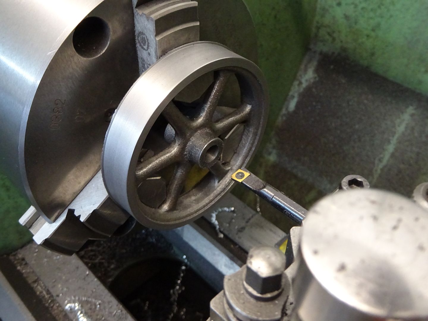
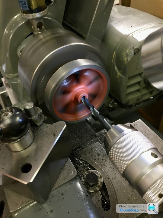
25215 forum posts 3105 photos 1 articles | Personally I never machine flywheels on an arbor and it is just asking for chatter and a poor finish. If possible hold by the inside of the rim in either 3 or 4 jaw chuck. Stuarts are usually fairly true once cleaned up with files so 3 jaw will do. This way you can machine the face, 1 side, hub face and then finally bore all at one setting ( I don't ream) then just flip it over to do the other side of rim and hub which don't need any concentricity. Drill drains first, 1/16" or 1.5mm hole will do, threaded hole about 1/16 to 3/32 short of cylinder
Edited By JasonB on 28/06/2020 10:08:58 |
| Dr_GMJN | 28/06/2020 11:40:21 |
1602 forum posts | Thanks Jason, that should keep me busy for a few days. |
| Dr_GMJN | 18/07/2020 17:07:43 |
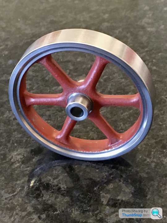
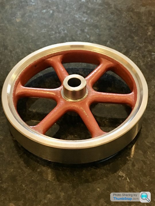
1602 forum posts | Got a bit sidetracked with this, but made a start on the flywheel this afternoon. |
| Dr_GMJN | 18/07/2020 22:56:52 |
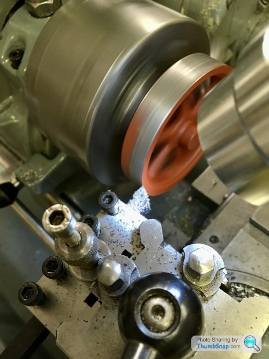
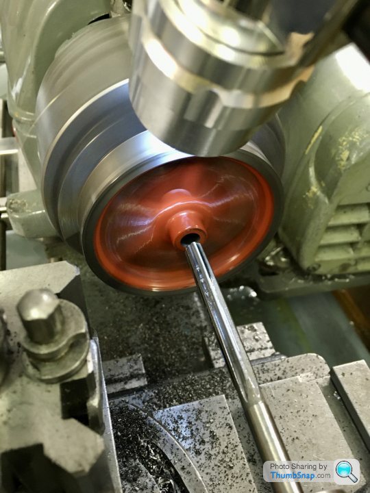
1602 forum posts | So I've done the corrections just in the 4-jaw chuck, all the machined bits seem pretty much spot-on true now, so just needs the screw hole drilling and tapping, then on to the standard and main bearing fitting. |
| Dr_GMJN | 19/07/2020 19:21:44 |
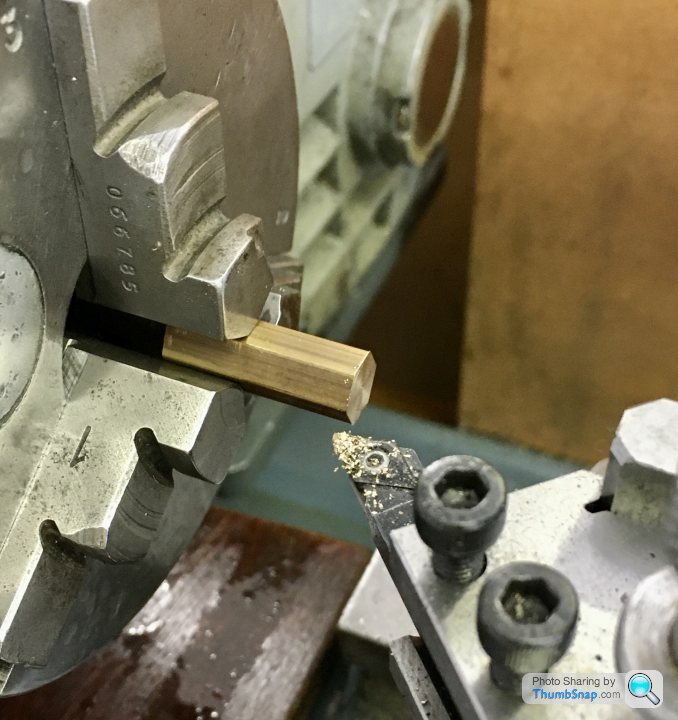
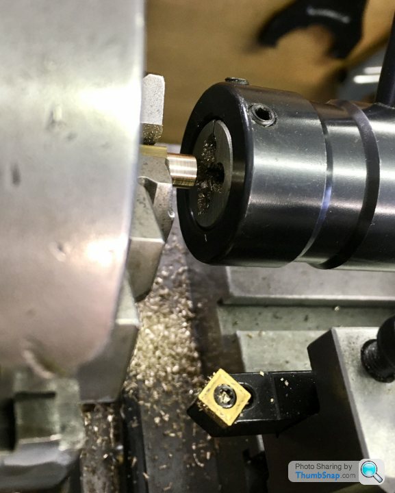
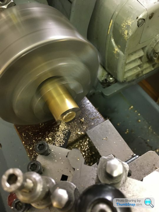
1602 forum posts | Quick bit of turning to get back into it: The valve rod packing nut. It’s turned from some hexagonal bar: |
| Dr_GMJN | 21/07/2020 18:15:06 |
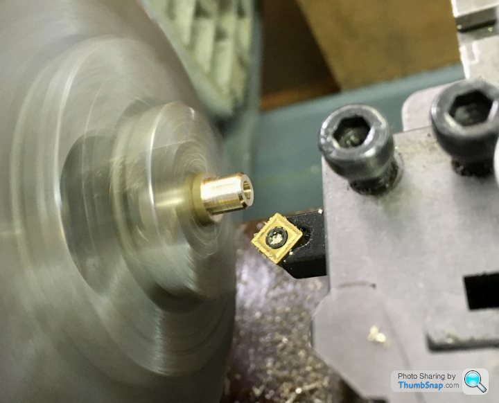
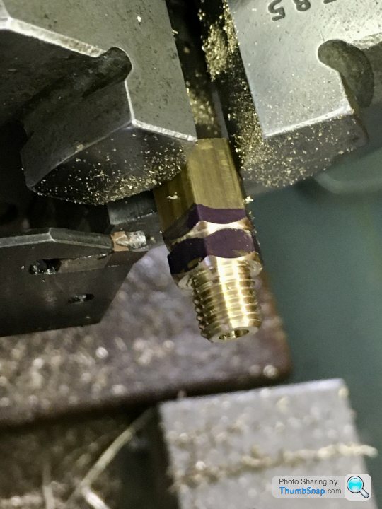
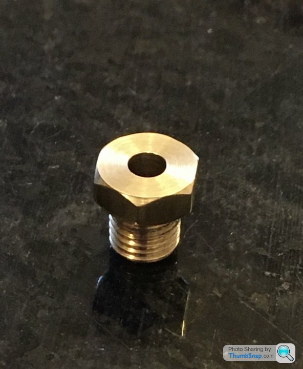
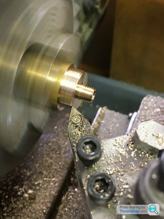
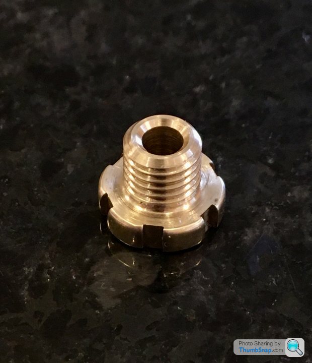
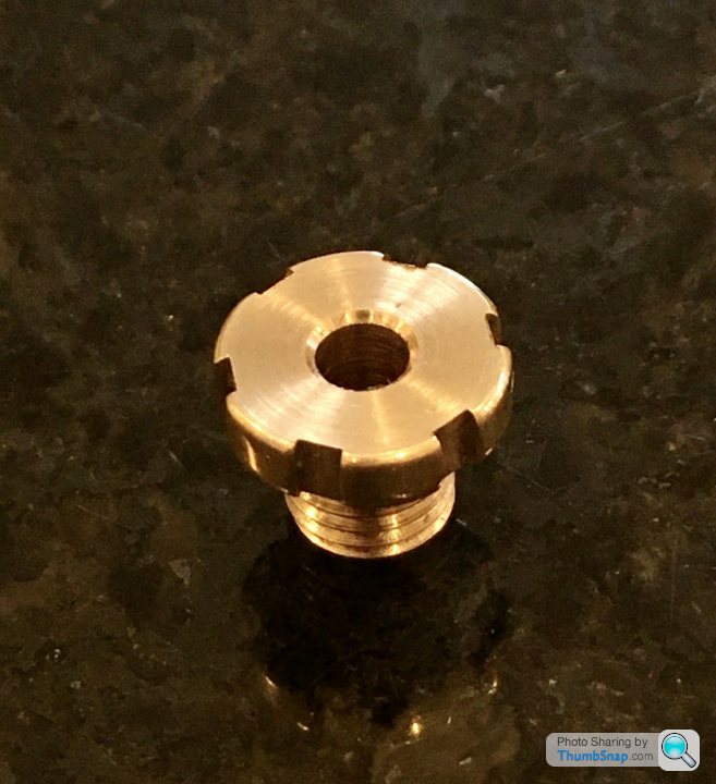
1602 forum posts | The piston rod seal packing nut is a bit different from the valve rod nut; it’s larger, and has screwdriver cut-outs for tightening instead of flats due to it fitting within the standard. It’s turned from the same brass stock suppled for the piston: |
| JasonB | 21/07/2020 18:24:01 |
25215 forum posts 3105 photos 1 articles | You are making good progress. A bit of slack in the gland nut threads won't hurt as it will allow them to self align with the rod should there be any slight misalignment. The compressed gland material should stop then from wanting to unwind. |
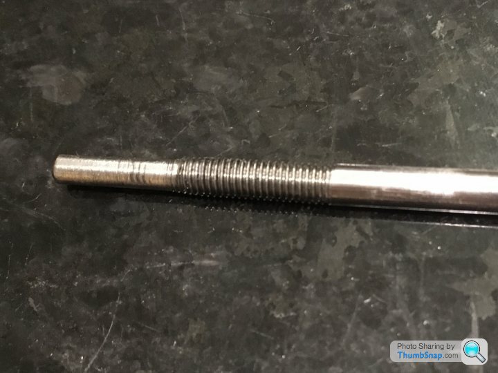
| Dr_GMJN | 22/07/2020 00:03:10 |
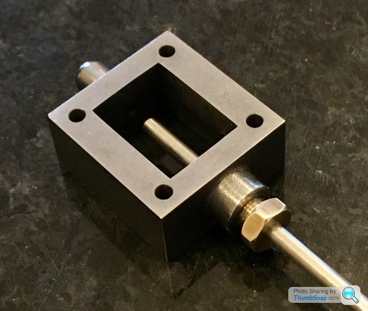
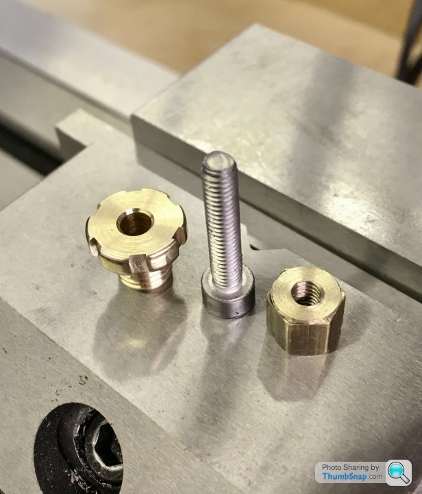
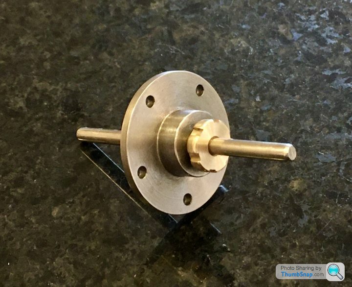
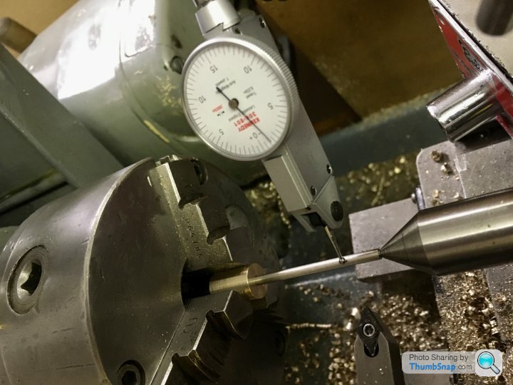
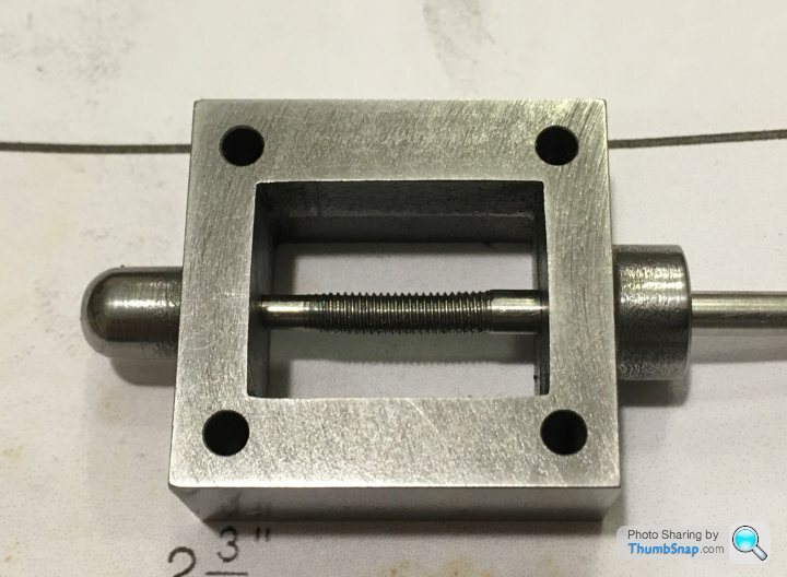
1602 forum posts | Thanks Jason. Unfortunately (and somewhat inevitably) this is where it all goes wrong... I could do with some advice on turning small diameter rods in silver steel/stainless. I've never been able to do it properly. In this case, I had to leave enough protruding from the chuck so I could remove the tail centre and keep test fitting it in the valve block, which is relatively deep. I'll need to nail a technicque for doing them for other critical parts that are on the horizon. If I do have to buy another valve chest casting and start again, I will do, but I'd really, really prefer not to. Thanks! |
| JasonB | 22/07/2020 07:24:05 |
25215 forum posts 3105 photos 1 articles | As you won't get a full depth of thread on the reduced diameter guide more a flat rod with a spiral groove I doubt it will make any difference to the running of the engine so you can make it to fit the hole then run the die down the lot. You did not say if you reduced the shaft to 3mm before cutting the M3 thread if not that could explain it being wonky and an old die will always struggle in stainless. Your biggest issue at the moment is the wayward thread as it may twist the valve nut and cause it to lift off the port face but that will depend to some extent how tight the valve nut thread is. ideally make a new rod same size to fit the end hole and thread 5BA as it is easier to do that now rather than having to mount the piston onto a replacement rod. Use one of your DCGT inserts on the stainless and in fact on any long slender work, your holding and tailstock support is fine. |
| Dr_GMJN | 22/07/2020 08:09:19 |
1602 forum posts | Thanks Jason. I will use the old rod to practice getting a good finish. I appreciate that a partial depth thread on the spigot end would probably be fine, functionally, but I just don’t like the thought of it being like that. I’d rather make it to size, and get it right. Apart from time and messing about, can you see any issue with plugging with brass and re-drilling? Apart from having to set-up the block in the 4-jaw again, I think I can get it true to a decent level. As you say, the gland seal seems to do most of the alignment, and the spigot just stops any major wobble. Thanks.
|
| Martin Connelly | 22/07/2020 09:31:40 |
 2549 forum posts 235 photos | Have you got a travelling steady? It helps with some jobs on long slender parts where only the end needs machining but it is not being done close to the chuck. Even a lashed up steady will help, it doesn't have to be pretty (I haven't got one but I think the Smart & Brown one is an ugly lump). Martin C |
| Dr_GMJN | 22/07/2020 10:47:21 |
1602 forum posts | Posted by Martin Connelly on 22/07/2020 09:31:40:
Have you got a travelling steady? It helps with some jobs on long slender parts where only the end needs machining but it is not being done close to the chuck. Even a lashed up steady will help, it doesn't have to be pretty (I haven't got one but I think the Smart & Brown one is an ugly lump). Martin C I do have a Myford one yes. I've only used it once (came in a box when I bought the lathe). I could give it a go. Thanks. |
| JasonB | 22/07/2020 13:05:06 |
25215 forum posts 3105 photos 1 articles | As you have things lined up already with the existing hole you could just loctite a sleeve into the hole. Make it a bit smaller say 1.8mm ID so it has some strength and turn the end of the rod down to suit. |
| Dr_GMJN | 22/07/2020 14:51:32 |
1602 forum posts | Posted by JasonB on 22/07/2020 13:05:06:
As you have things lined up already with the existing hole you could just loctite a sleeve into the hole. Make it a bit smaller say 1.8mm ID so it has some strength and turn the end of the rod down to suit.
There's an idea. I've got a load of brass tube for modelling. I wonder if some might happen to fit... Anyway it looks like this evening's entertainment is arranged. I have *just* enough rod spare to try once more. No room for error though. |
| Ramon Wilson | 22/07/2020 15:05:33 |
 1655 forum posts 617 photos | Hi Dr G, still following your progress.
Just a thought you might like to consider on the valve rod set up. Instead of threading the rod and valve nut just have a nut that has a small grub screw set into lock the nut in position. The big advantage of this is that when setting the valve you do not have to keep breaking the valve linkage apart in order to make adjustment by turning the valve rod. I used this idea which was passed to me by 'KBC' over on MEM when rebuilding my ST twin. It works really well, does not slip and has simplified valve setting no end. I pass it on in the same spirit that George did
Regards - Ramon Edited By Ramon Wilson on 22/07/2020 15:06:19 |
| Dr_GMJN | 22/07/2020 22:36:37 |
1602 forum posts | Posted by Ramon Wilson on 22/07/2020 15:05:33:
Hi Dr G, still following your progress.
Just a thought you might like to consider on the valve rod set up. Instead of threading the rod and valve nut just have a nut that has a small grub screw set into lock the nut in position. The big advantage of this is that when setting the valve you do not have to keep breaking the valve linkage apart in order to make adjustment by turning the valve rod. I used this idea which was passed to me by 'KBC' over on MEM when rebuilding my ST twin. It works really well, does not slip and has simplified valve setting no end. I pass it on in the same spirit that George did
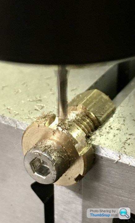
Regards - Ramon Edited By Ramon Wilson on 22/07/2020 15:06:19 Thanks Ramon, that's a very neat idea. I wish I'd have heard of it before trying to thread the un-threadable. I only just read your post, and have spent this evening trying to correct the valve chest hole (outlined below). If I have further issues with the thread, I'll use your grub screw method. Thanks very much. |

Please login to post a reply.
Magazine Locator
Want the latest issue of Model Engineer or Model Engineers' Workshop? Use our magazine locator links to find your nearest stockist!
Sign up to our Newsletter
Sign up to our newsletter and get a free digital issue.
You can unsubscribe at anytime. View our privacy policy at www.mortons.co.uk/privacy
Latest Forum Posts
- *Oct 2023: FORUM MIGRATION TIMELINE*
05/10/2023 07:57:11 - Making ER11 collet chuck
05/10/2023 07:56:24 - What did you do today? 2023
05/10/2023 07:25:01 - Orrery
05/10/2023 06:00:41 - Wera hand-tools
05/10/2023 05:47:07 - New member
05/10/2023 04:40:11 - Problems with external pot on at1 vfd
05/10/2023 00:06:32 - Drain plug
04/10/2023 23:36:17 - digi phase converter for 10 machines.....
04/10/2023 23:13:48 - Winter Storage Of Locomotives
04/10/2023 21:02:11 - More Latest Posts...
- View All Topics
Support Our Partners


Shopping Partners
Subscription Offer

Latest "For Sale" Ads
- Reeves** - Rebuilt Royal Scot by Martin Evans
by John Broughton
£300.00 - BRITANNIA 5" GAUGE James Perrier
by Jon Seabright 1
£2,500.00 - Drill Grinder - for restoration
by Nigel Graham 2
£0.00 - WARCO WM18 MILLING MACHINE
by Alex Chudley
£1,200.00 - MYFORD SUPER 7 LATHE
by Alex Chudley
£2,000.00 - More "For Sale" Ads...
Latest "Wanted" Ads
- D1-3 backplate
by Michael Horley
Price Not Specified - fixed steady for a Colchester bantam mark1 800
by George Jervis
Price Not Specified - lbsc pansy
by JACK SIDEBOTHAM
Price Not Specified - Pratt Burnerd multifit chuck key.
by Tim Riome
Price Not Specified - BANDSAW BLADE WELDER
by HUGH
Price Not Specified - More "Wanted" Ads...
Get In Touch!
Do you want to contact the Model Engineer and Model Engineers' Workshop team?
You can contact us by phone, mail or email about the magazines including becoming a contributor, submitting reader's letters or making queries about articles. You can also get in touch about this website, advertising or other general issues.
Click THIS LINK for full contact details.
For subscription issues please see THIS LINK.
Digital Back Issues


Donate

 Register
 Log-in
Model Engineer Magazine
- Percival Marshall
- M.E. History
- LittleLEC
- M.E. Clock

ME Workshop
- An Adcock
- & Shipley
- Horizontal
- Mill

Subscribe Now
- Great savings
- Delivered to your door

Pre-order your copy!
- Delivered to your doorstep!
- Free UK delivery!
All Forum Topics > Work In Progress and completed items > Stuart 10V Build Log - Complete Beginner...