Forum sponsored by:

Stuart Twin Victoria (Princess Royal) Mill Engine
| JasonB | 27/05/2021 07:12:41 |
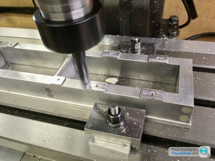
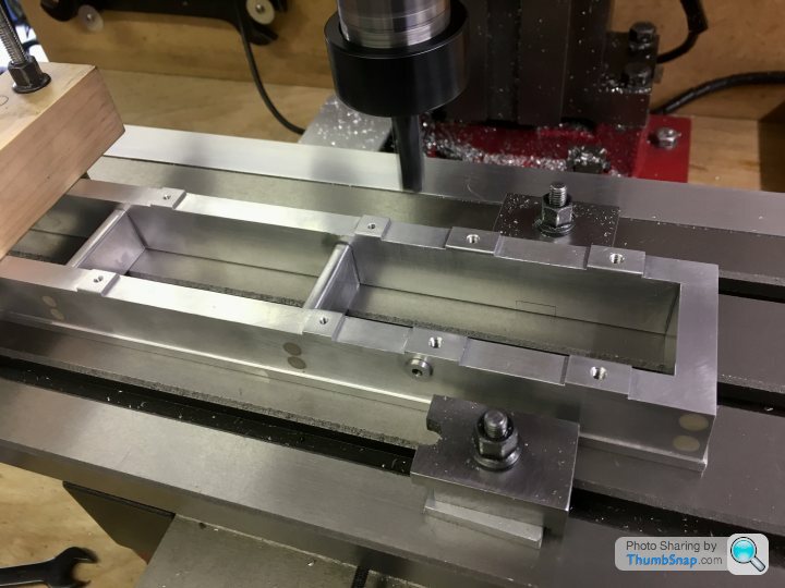
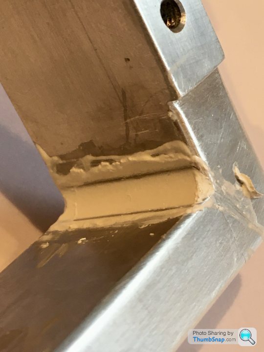
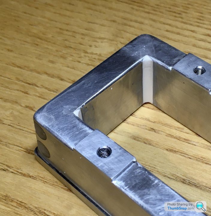
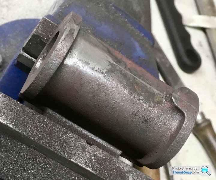
 25215 forum posts 3105 photos 1 articles | Take a cut at say 1.2mm from stock top and then measure how high that side is compared to the other and lower your tool by the difference. Probably would have been better to do upto the edge of the cross head guide pad and not the narrow cut the other side then no blending needed, if you have the movement with the second setup I'd set it to just skim upto the edge of those pads At the end of the day you are replicating a casting and some deviation is desirable and helps make it look like a casting rather than painted barstock. Look at this shot of where I machined off the unused bearing pad on the Victoria I did recently, one end is about 5 thou above the surrounding cast surface the other a similar amount below and thats over 2" distance.
All blends in fine with a bit of Dremel, file and Emery work
|
| Dr_GMJN | 27/05/2021 08:51:22 |
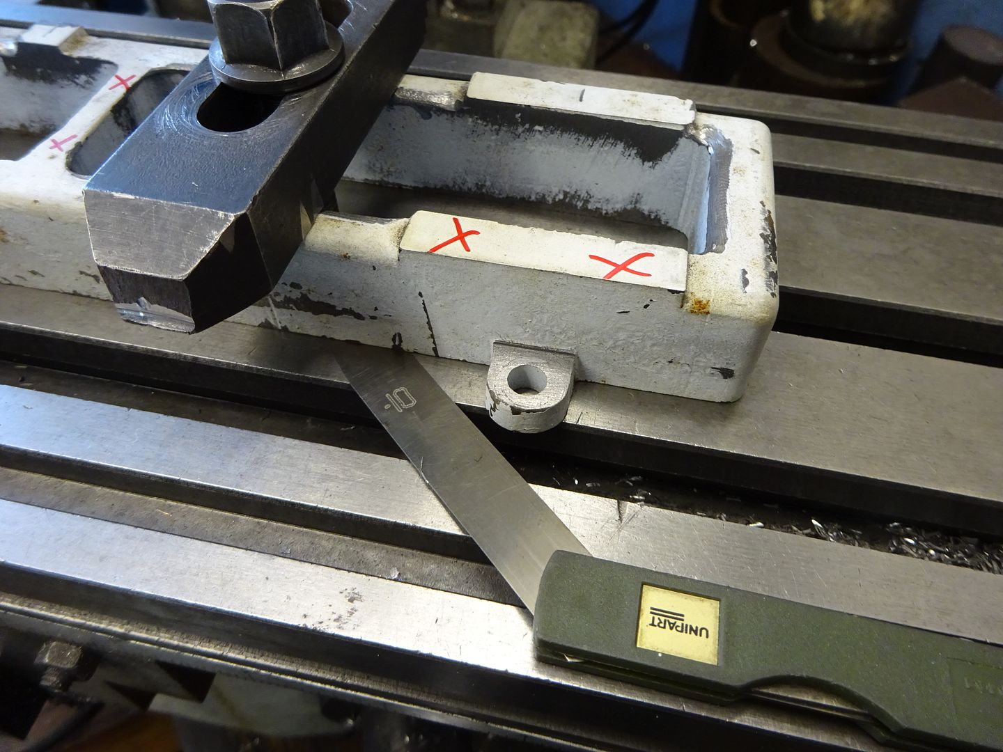
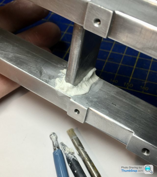
 1602 forum posts | Thanks Jason. Yes, the initial idea was to do as you suggested and machine up to one side of the right hand pad. I changed my mind because I wanted all four pads exactly the same length, and was using the DRO datumed on the left inner edge of the bed. If I'd have only machined one side, any error in the bed length would have thrown out the DRO reading when re-datumed at the other end after swapping the part on the bed. OK it seems less than 0.5mm, but I didn't want to take any chances - my mill bed and all my accurate measuring equipment can't accommodate these part lengths in one go. I suppose I could have machined to the scribed lines, but I went down the track of getting pad widths perfect rather than simplifying bed height match. Anyway, it'll be fine once sanded. I did notice in the article that it was suggested to relieve the centre and end undersides of the bed, to guarantee the pads contact. Is that what you're checking with the feeler gauge in the picture? I thought of finishing everything, then just flatting the middle and ends with abrasive paper just to give a fraction of clearance. At present they're flat all over. |
| JasonB | 27/05/2021 10:58:41 |
25215 forum posts 3105 photos 1 articles | The bed had been part machined when I got it and the bottom possibly just filed which meant it rocked on the mill table so I shimmed it up with feeler gauges so that the clamps would not distort the bed and subsequently machined the tops of all the pads and the bottom flat. |
| Dr_GMJN | 06/06/2021 20:35:43 |
1602 forum posts | Back on this one after a week in deepest West Wales... |
| JasonB | 07/06/2021 06:48:09 |
25215 forum posts 3105 photos 1 articles | I've not had problems with the Milliput staying put. Just test any etch primers on a bit first as I did have one that affected the surface. |
| Dr_GMJN | 08/06/2021 00:08:08 |
1602 forum posts | Posted by JasonB on 07/06/2021 06:48:09:
I've not had problems with the Milliput staying put. Just test any etch primers on a bit first as I did have one that affected the surface.
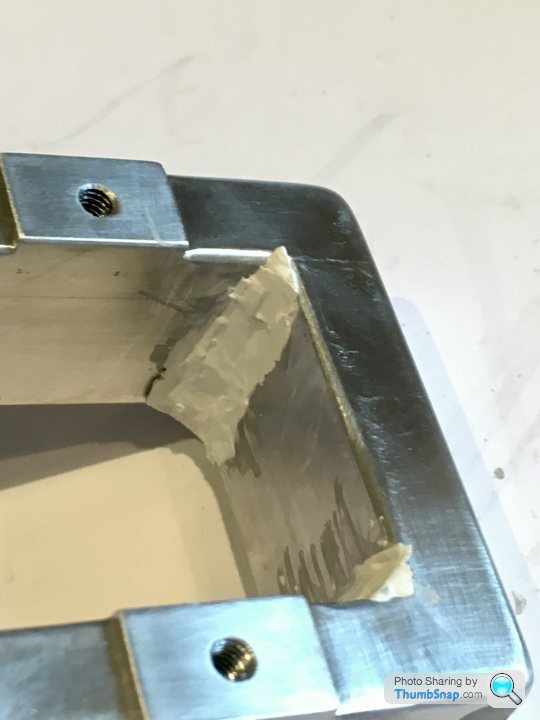
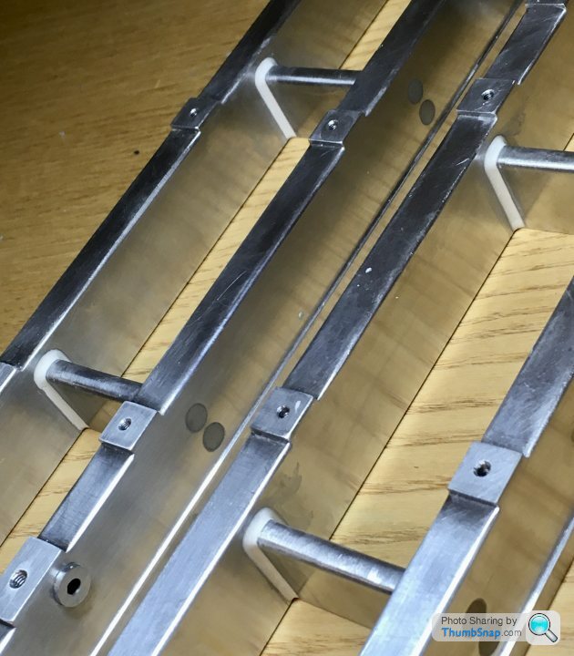
Same here - it should be OK I think, although in the past I've only really used it on plastic. Made a start by squidging some Milliput into the appropriate corners: |
| Dr_GMJN | 10/06/2021 22:25:06 |
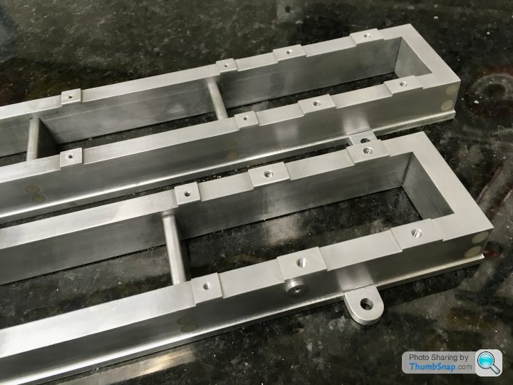
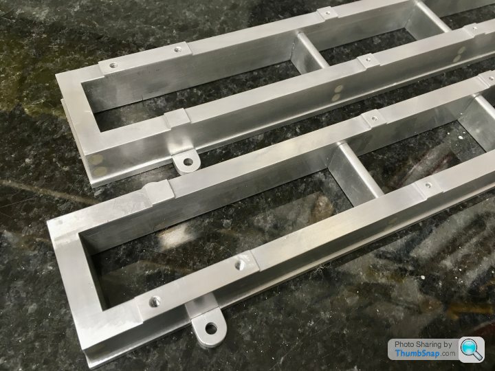
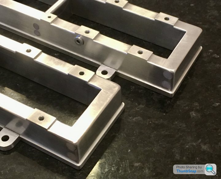
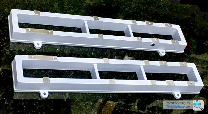
1602 forum posts | Finished the Milliputing of the radii, flatting the excess and feathering off any rough edges, then abraded all over with Scotchbrite: Anyway thanks to Jason and Ramon for the idea, and the advice along the way. At last some results after a long build thread with no actual building! |
| Ramon Wilson | 10/06/2021 22:56:42 |
 1655 forum posts 617 photos | A really excellent result after a great deal of thought going in to their manufacture. They certainly look convincing from here. Great job Doc G
Ramon
|
| Dr_GMJN | 10/06/2021 23:10:41 |
1602 forum posts | Posted by Ramon Wilson on 10/06/2021 22:56:42:
A really excellent result after a great deal of thought going in to their manufacture. They certainly look convincing from here. Great job Doc G
Ramon
Thanks Ramon, much appreciated. Yes, some thought and planning, perhaps too much for what they are, yet still some mistakes (to learn from)! Anyway - the result is what counts, I hope everything fits! Cheers. |
| JasonB | 11/06/2021 06:58:51 |
25215 forum posts 3105 photos 1 articles | A good indicator to how well the rest of the engine should turn out. If you do feel you want a bit more texture then spraying with low pressure or an old can of primer can give a slightly more lumpy finish or I have even stippled primer on in the past. You can also run the edge of a slow running grinding bit or burr in a Dremel against the surfaces. However let's not forget the scale of this engine which is a lot smaller than the original 1/5th scale of Victoria so any texture left from casting will be next to nothing. Think of it like abrasive paper, the original may have had a 60g texture at about 1/18th scale yours will be more like 1000g Edited By JasonB on 11/06/2021 07:21:09 |
| Dr_GMJN | 11/06/2021 07:52:33 |
1602 forum posts | Posted by JasonB on 11/06/2021 06:58:51:
A good indicator to how well the rest of the engine should turn out. If you do feel you want a bit more texture then spraying with low pressure or an old can of primer can give a slightly more lumpy finish or I have even stippled primer on in the past. You can also run the edge of a slow running grinding bit or burr in a Dremel against the surfaces. However let's not forget the scale of this engine which is a lot smaller than the original 1/5th scale of Victoria so any texture left from casting will be next to nothing. Think of it like abrasive paper, the original may have had a 60g texture at about 1/18th scale yours will be more like 1000g Edited By JasonB on 11/06/2021 07:21:09 Thanks Jason. Yes I thought of spraying Mr. Surfacer (a filler primer for models) at low pressure from a distance, or even getting a spatter cap for the airbrush. I’ll experiment with that when the time comes to finally paint it. |
| Dr_GMJN | 19/06/2021 08:25:09 |
1602 forum posts | Hoping to make a start on the cylinders today - at least cleaning them up ready for attaching their feet. The article says use 1/2” x 1/2” steel for them, which I’ve bought. Unfortunately, while I got more than enough for four lengths, I effectively need six, because I want to try using the three strips soldered together method for boring the arcs. Any ideas how to get around this, or just buy more steel? Thanks. |
| JasonB | 19/06/2021 10:01:55 |
25215 forum posts 3105 photos 1 articles | You don't need a full strip in the middle so short bits will do or anything that could be cut to 1/2" long. Don't forget to poke some fuse wire down the cast steam passages as they are often still full of core sand and you don't want to go spreading that over your machines
|
| Dr_GMJN | 19/06/2021 12:37:20 |
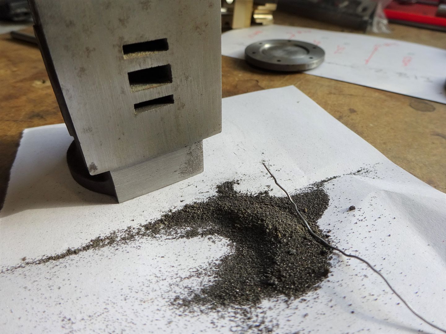
1602 forum posts | Thanks Jason. I’m not sure if I’ve misunderstood the concept - the image in the article is just a blur. |
| JasonB | 19/06/2021 13:07:29 |
25215 forum posts 3105 photos 1 articles | That's it. The intermittant cut should not be an issue and if you had the "spacers" a little closer together in your sketch then the final cuts will be constant. A loose packer at either end will spread the load rather than push against the central soldered in packers, infacct arranged that way you could use superglue rather than solder as then it is only a case of stopping the bits sliding about when initially clamping.
|
| Dr_GMJN | 19/06/2021 13:35:59 |
1602 forum posts | Great - thanks Jason. |
| Clive Brown 1 | 19/06/2021 16:39:46 |
| 1050 forum posts 56 photos | Clearly a nice model coming along. Might I make a suggestion; when building my Victoria recently, I made the cylinder supports from 1" BMS angle. The web is deep enough to allow marking of the centre of the 1/2" radius and the other web allows holding in the 4-jaw for machining out the curve. Afterwards it is sawn away, filed and drilled to form the mounting feet. Simple and saves quite a bit of milling away of surplus material. Incidentally, as with the OP, the bed of my engine is fabricated from aluminium flat, helped along with epoxy filler, but of more plain appearance without a flanged lower edge. |
| Dr_GMJN | 19/06/2021 17:58:32 |
1602 forum posts | Posted by Clive Brown 1 on 19/06/2021 16:39:46:
Clearly a nice model coming along. Might I make a suggestion; when building my Victoria recently, I made the cylinder supports from 1" BMS angle. The web is deep enough to allow marking of the centre of the 1/2" radius and the other web allows holding in the 4-jaw for machining out the curve. Afterwards it is sawn away, filed and drilled to form the mounting feet. Simple and saves quite a bit of milling away of surplus material. Incidentally, as with the OP, the bed of my engine is fabricated from aluminium flat, helped along with epoxy filler, but of more plain appearance without a flanged lower edge. Thanks Clive - looks like a very nice model. The feet an mine are different - they fit underneath. They are made from machined 1/2" x 1/2" steel, profiled to fit the cylinder, and screwed into it with JB Weld as a gap filler. They are meant to look like cast-in features once complete. |
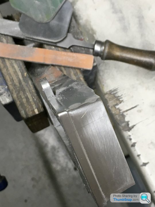
| Dr_GMJN | 19/06/2021 17:59:37 |
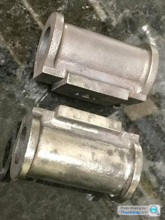
1602 forum posts | So on to the cylinders - I needed to clean them up to get an idea of the diameter to machine into the modified feet blocks. This all took longer than I thought, so the feet will have to wait for a few more days... |
| Clive Brown 1 | 19/06/2021 18:54:27 |
| 1050 forum posts 56 photos | Apologies, I hadn't twigged that your proposed feet were integral with the cylinder. I was going by my "single". Should've looked at the diagrams more closely, In fact, from looking at Google images, are both types of foot used for the twin?
|


Please login to post a reply.
Magazine Locator
Want the latest issue of Model Engineer or Model Engineers' Workshop? Use our magazine locator links to find your nearest stockist!
Sign up to our Newsletter
Sign up to our newsletter and get a free digital issue.
You can unsubscribe at anytime. View our privacy policy at www.mortons.co.uk/privacy
Latest Forum Posts
- *Oct 2023: FORUM MIGRATION TIMELINE*
05/10/2023 07:57:11 - Making ER11 collet chuck
05/10/2023 07:56:24 - What did you do today? 2023
05/10/2023 07:25:01 - Orrery
05/10/2023 06:00:41 - Wera hand-tools
05/10/2023 05:47:07 - New member
05/10/2023 04:40:11 - Problems with external pot on at1 vfd
05/10/2023 00:06:32 - Drain plug
04/10/2023 23:36:17 - digi phase converter for 10 machines.....
04/10/2023 23:13:48 - Winter Storage Of Locomotives
04/10/2023 21:02:11 - More Latest Posts...
- View All Topics
Support Our Partners


Shopping Partners
Subscription Offer

Latest "For Sale" Ads
- Reeves** - Rebuilt Royal Scot by Martin Evans
by John Broughton
£300.00 - BRITANNIA 5" GAUGE James Perrier
by Jon Seabright 1
£2,500.00 - Drill Grinder - for restoration
by Nigel Graham 2
£0.00 - WARCO WM18 MILLING MACHINE
by Alex Chudley
£1,200.00 - MYFORD SUPER 7 LATHE
by Alex Chudley
£2,000.00 - More "For Sale" Ads...
Latest "Wanted" Ads
- D1-3 backplate
by Michael Horley
Price Not Specified - fixed steady for a Colchester bantam mark1 800
by George Jervis
Price Not Specified - lbsc pansy
by JACK SIDEBOTHAM
Price Not Specified - Pratt Burnerd multifit chuck key.
by Tim Riome
Price Not Specified - BANDSAW BLADE WELDER
by HUGH
Price Not Specified - More "Wanted" Ads...
Get In Touch!
Do you want to contact the Model Engineer and Model Engineers' Workshop team?
You can contact us by phone, mail or email about the magazines including becoming a contributor, submitting reader's letters or making queries about articles. You can also get in touch about this website, advertising or other general issues.
Click THIS LINK for full contact details.
For subscription issues please see THIS LINK.
Digital Back Issues


Donate

 Register
 Log-in
Model Engineer Magazine
- Percival Marshall
- M.E. History
- LittleLEC
- M.E. Clock

ME Workshop
- An Adcock
- & Shipley
- Horizontal
- Mill

Subscribe Now
- Great savings
- Delivered to your door

Pre-order your copy!
- Delivered to your doorstep!
- Free UK delivery!
All Forum Topics > Work In Progress and completed items > Stuart Twin Victoria (Princess Royal) Mill Engine