Member postings for Gerald Weare
Here is a list of all the postings Gerald Weare has made in our forums. Click on a thread name to jump to the thread.
| Thread: Unable to access digital version. |
| 26/11/2012 19:06:19 |
Me too (USA, if that is relevant). I had no problem entering the sub number on Nov 9th when I subscribed, though it stripped the two leading zeros. It was working fine since then until about 2 hours ago. I initially used my PC, but switched to a new tablet last night. I tried just now to access from my PC, got the "Subscriber only content" message. I tried re-entering the sub number, again it strips the zeros and seems happy, but it did not help. I now cannot access from either PC or tablet. I'm thinking a website glitch (hopefully temporary). or something to do with switching between PC and tablet?
Jed |
| Thread: Spindle Speed |
| 04/02/2010 23:17:36 |
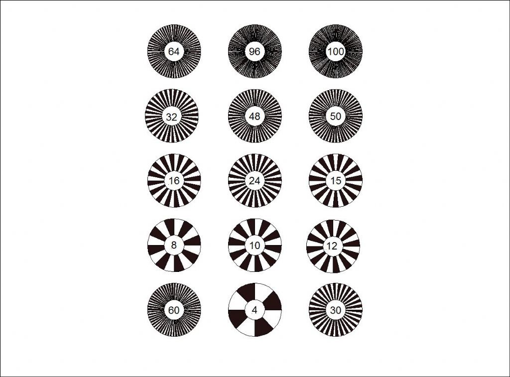
Oh, if you want strobe patterns, the best thing is to do them in CAD, just takes a few minutes. As an example, there is a JPG in my album of some I made when I was messing with the tacho. I printed a bunch on a single sheet, to see what worked. Funnily, one pulse per rev is as good as any...
 Jed |
| 04/02/2010 23:11:01 |
A hand-held unit is a good thing, I have a cheap chinese one that I use in my business, it works fine, but you have to hold it, not surprisingly. The other alternative, which was discussed at length in the recent thread called "Tachometer Design", is a built-in add-on device. There was a kit offered ny someone on the web about 8 years ago, based on a PIC microprocessor. Don't know if it worked, but I built one for myself, see the pictures in my album. This has the virtue of being always on, versus the handheld unit.
A last alternative, since you have a VFD, is to use the speed output(s) of the VFD. All VFDs I have ever seen have an output that gives the speed it is set to, or the speed it is actually going at. This may be an analogue output, typically 0-10V DC for 0 to max configured speed. Hook it up to a 10V meter, either a digital panel meter with a couple of resistors or a moving coil if you can find one (you could just use a multimeter too, they are pretty cheap these days). Other VFDs may havea digital output of some kind, but usually they are designed for use with CNC.
Both of my VFDs (one is Allen-Bradley, the other AC Tech) can be set up to display the speed on the VFD front panel itself (but some VFDs have no front panel). You can typically scale the output (by setting VFD parameters) so that it displays any desired relationship between motor frequency (Hz) and the actual spindle speed. Unfortunately, if you have a gearbox, or change speed device, this changes when you change the belts or change gears. The fancier VFDs can accept a gear number input and use the appropriate ratio, but not the simple ones like mine.
What I did on my machines is to make the little PIC tachometer for the mill, as I change gears a lot but it isn't easy to do, so I use the variable speed feature quite a bit. However on the lathe, there are a lot of gears and it is easy to change, so I only really use the VFD as a 3-phase converter. I did create a spreadsheet to convert the VFD frequency to RPM for each gear, but I rarely use it.
One last thopught: if you have no speed output, you will have a speed input to the VFD. This is usually a potentiometer. If you measure this voltage (again it usually goes from 0 to 10V), you can see what speed is being commanded.
Jed |
| Thread: Information on a Gallenhamp Oven |
| 04/02/2010 22:44:01 |
Just FYI, Type K is the most common type of thermocouple for this kind of temperature, and that's probably what's in the oven already. It is also the most common type you find with the multimeters that have a temperature range. The controllers I mentioned list a lot of compatible thermocouple types (and I mean a lot), and you just configure them for the type you have. Very impressive.
Jed |
| Thread: Tachometer design |
| 01/02/2010 08:29:35 |
As one who has built a number of very successful tachos using the 16F628, the comparators are neither here nor there. You need to have a digital filter in any case, so the hysteresis of the regular Schmitt trigger digital ports is fine. In any event, I don't believe the comparators have any hysteresis? Been a while since I looked at them. Plus you probably need pull-ups for the comparators. My tachos work just as well on a 16F84 as the '628. All you need of the PIC is one input and enough output bits for the display. What does seem to help a lot is to have an IR detector (or gear tooth sensor if that's what you like) with a built-in Schmitt trigger. Saves a chip. I use nothing but the PIC standard I/O port and the sensor.
BTW, I can recommend the use of the FED (Forest Electronic Development) PIC C compiler package. It is full featured, including assembler, libraries for all the PIC subsystems, for driving LED and LCD displays and other devices, development environment, simulator, etc.. Very reasonably priced too, and good support. Of course Microchip also has their free MPLAB environment which is fine, but last time I looked they were charging for the C compiler.
They also have an AVR product, but I have never used that chip. |
| Thread: Information on a Gallenhamp Oven |
| 30/01/2010 15:19:33 |
Vic, Bitterly cold, hmmm. It was 4.5F last night when I went to bed, that's -15C. The wind was about 25 mph, it was howling. When I first came here, in July 1981, a guy from Glasgow (not known for high temperatures) told me, within 10 minutes of meeting him, to buy a down jacket and a snow shovel. It was on his mind. Once I had found out what those things were, I was worried. The weather here in the Boston area really kills you, to the extent that I miss English weather. Of course, it can get REALLY cold up north in New Hampshire or Maine or Quebec... That aside, you should be able to get those controllers. Some are shipped direct from Hong Kong, and I am sure most of the US or Canadian suppliers would ship them to UK. The non-Chinese brands are a common industrial control/lab item, and they should be easy to get also. The price would naturally be much higher for non-Chinese. Talk to your firend and have him take a look on the web and I am sure he will agree there isn't an easier or cheaper way to go. And it is certailny well worthwhile. Good luck. |
| 30/01/2010 05:20:43 |
Hi, An oven like that is a great device. I bought a Thermoline on eBay for not much, and I love it. It uses about 1500W, but is about the same size as yours. I can get it easily to over 2200F or 1250C, well it takes a while to get there. When I got it, it had a thermocouple/analogue meter and a bimetal strip power controller, not very precise. I decided an electronic control was the thing, so I built a microprocessor controller using the thermocouple input to control a triac (like a lamp dimmer). It also had a heating timer and was going to (but did not actually) have many fancy features. I can set and keep the temperature within 1 degree C (truly!). So I would recommend you rig up some kind of feedback control of the temperature. You don't have to do your own, these days there are standard off the shelf devices that could be used easily. I just saw a Chinese version for 40USD, a digital temperature controller on eBay that could be used with a standard solid state relay, or even a regular power relay wired into the power cable to an existing oven. You would need to hook up the thermocouple, that is the only modification required to the oven. If you want to pay more, non-Chinese versions are readily available, going for maybe $120 US. I haven't tried these devices, but I can't see how they would not be great. They look good and the specs are impressive (they seem to do everything), and though you don't get the timing functions I put into mine, the price is right. |
| Thread: Electrical Discharge Machine - Spark Erroder... |
| 23/01/2010 17:28:33 |
Hi,
If you need it I have a PDF of the two articles mentioned, from JUly/Aug 1976 by Roy Amsbury. I actually got it off the web at www.metalwebnews.com/manuals/spark-erosion.pdf but I can email you a copy if you'd rather. (Don't know why that went green)
Roy published another article in 1980 with some improvements and changes for out of date electronic parts. This is also included in that same PDF. You might have trouble finding the stepper and stepper driver chip, but there is plenty of info on the web about building such things - much better these days than 1980. Personally, I think I would build it as an attachment for my cnc mill and program the vertical motion, thus eliminating the stepper motor and drive electronics. You could also program the X and Y, which would greatly expand the scope of Roy's machine. The drive really isn't much more than a slow power feed, as you can control the speed but not position. If you had a slow enough Z axis feed on your manual mill or drill, you wouldn't need the stepper motor and electronics even for non-CNC. Of course, you still need the spark generator.
As far as safety, it looks OK to me, as far as 250V to a sharp-pointed electrode can be safe! I would be pretty happy to trust Roy's design anyway, seeing as he was a well-respected electronics engineer at Rolls-Royce Derby for many years. Having personally seen both his electronics work and his live steam work, I can assure you he was both a genius and a true craftsman. |
| Thread: Tachometer design |
| 22/01/2010 06:11:43 |
Hi all, Just noticed this thread, and unfortunately not able to thoroughly read all the items, but I though you might be interested in this. I have uploaded some photos of two versions of a tachometer I built back in 2002, using essentially the same idea: a PIC with a sensor and LED displays. I intended to market the devices in several forms, but never did. I built two prototype versions. This is the first one:
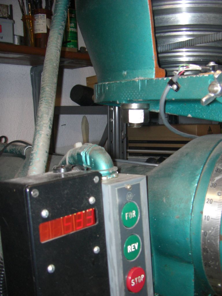 This shows the tacho mounted in a large black box to the side of my Millrite mill, doing 533 RPM under VFD control. The display is a set of 5 reasonably large LEDs,and the sensor can just be seen top right just above the wing nut. Here is a closeup:
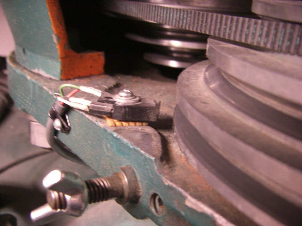 The sensor is a reflective all-in-one device with included Schmitt trigger, so interfaces directly to a PIC data input port. The reflective element is the bottom part of the bright aluminium spindle pulley, which. I covered approximately half of the circumference with matt black crepe self-adhesive tape, so we are getting one pulse per rev. This is the second prototype:
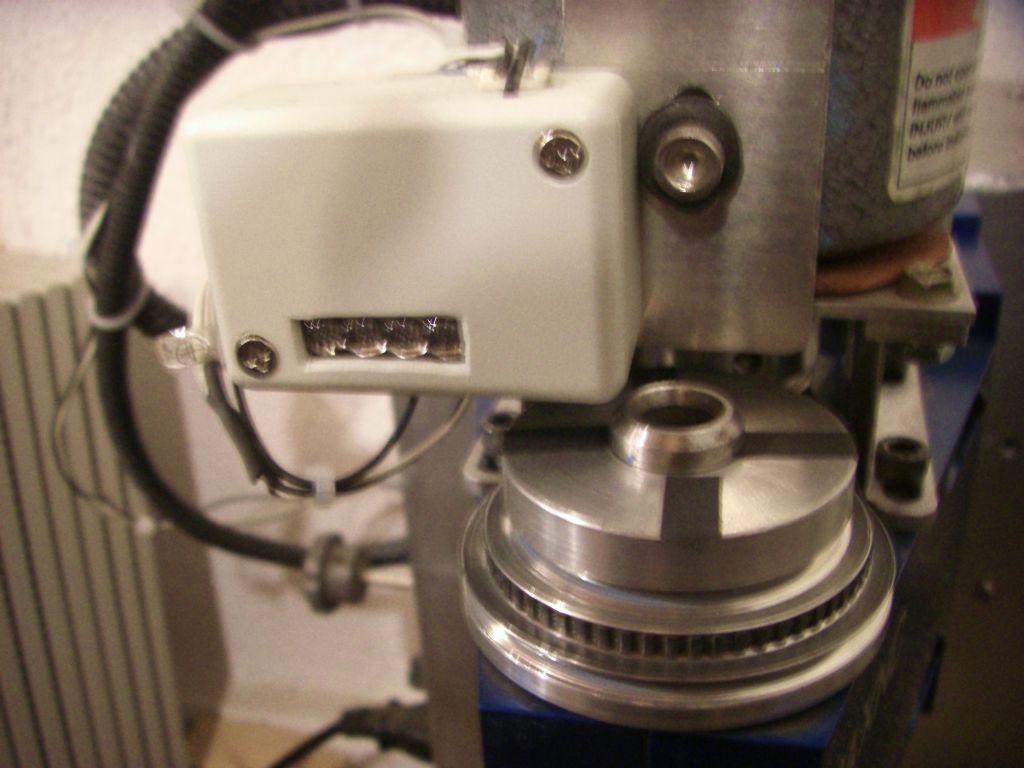 It is much smaller. The box is 2-2/8 x 1-3/8. There are four pulses per rev in this case, given by four strips of crepe tape on the top of the MAXNC spindle pulley. Here is the inside of the box: 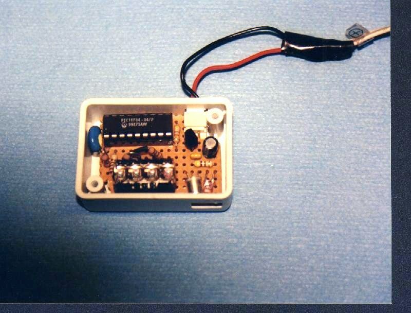 The display is a stick of four 0.1" LED digits. These were bought in 1972 and are impossible to find today. I did a design using the smallest available displays, and it would just fit in this box, along with the PIC, the regulator and the sensor. The sensor is also reflective, but using separate LED and detector, but again one with a Schmitt trigger built-in. The real secret is the software in the PIC. The algorithm is quite sophisticated. The input from the detector (1 or 0) is sampled at at least four times the maximum input frequency. It is then digitally filtered to provide smooth edge events. Following that, the period between events, or events per period, is measured and used to determine if there is movement (for display blanking), and a further digital filter and scaling unit provides the measured speed in the desired units. The unit self-adapts to measure the frequency at high RPMs and the period at low RPMs. This provides a stable display with a reasonable response time and resolution.
It turns out that you do not need many pulses per rev. One is enough for the Millrite, though I used four on the MAXNC because there was more noise from ambient light and because the sensor is inferior. Any more caused problems with the sampling rate, though it is a slow/old/small PIC (16F84). However, you cannot just measure the period of each pulse; you do need some decent filtering, or the display tends to be garbage, jumping all over the place. It is worse with more pulses per rev, because of the unevenness of the reflective areas (unless you want to use an expensive encoder-quality rotor instead of black tape).
As a further project, I took the raw output from the sensor to a closed-loop motor control chip. I would have liked to pre-process it in the PIC first, but not enough pins. This worked well, giving full torque from the MAXNC motor down below 200 RPM. Ideally, the PIC should control the motor directly. I also fed it to my EMC2 CNC software to (eventually) provide closed-loop CNC speed control, but unfortunately it needs more work on the PC side before it can be useful. |
Magazine Locator
Want the latest issue of Model Engineer or Model Engineers' Workshop? Use our magazine locator links to find your nearest stockist!
Sign up to our Newsletter
Sign up to our newsletter and get a free digital issue.
You can unsubscribe at anytime. View our privacy policy at www.mortons.co.uk/privacy
Latest Forum Posts
- *Oct 2023: FORUM MIGRATION TIMELINE*
05/10/2023 07:57:11 - Making ER11 collet chuck
05/10/2023 07:56:24 - What did you do today? 2023
05/10/2023 07:25:01 - Orrery
05/10/2023 06:00:41 - Wera hand-tools
05/10/2023 05:47:07 - New member
05/10/2023 04:40:11 - Problems with external pot on at1 vfd
05/10/2023 00:06:32 - Drain plug
04/10/2023 23:36:17 - digi phase converter for 10 machines.....
04/10/2023 23:13:48 - Winter Storage Of Locomotives
04/10/2023 21:02:11 - More Latest Posts...
- View All Topics
Support Our Partners


Shopping Partners
Subscription Offer

Latest "For Sale" Ads
- Reeves** - Rebuilt Royal Scot by Martin Evans
by John Broughton
£300.00 - BRITANNIA 5" GAUGE James Perrier
by Jon Seabright 1
£2,500.00 - Drill Grinder - for restoration
by Nigel Graham 2
£0.00 - WARCO WM18 MILLING MACHINE
by Alex Chudley
£1,200.00 - MYFORD SUPER 7 LATHE
by Alex Chudley
£2,000.00 - More "For Sale" Ads...
Latest "Wanted" Ads
- D1-3 backplate
by Michael Horley
Price Not Specified - fixed steady for a Colchester bantam mark1 800
by George Jervis
Price Not Specified - lbsc pansy
by JACK SIDEBOTHAM
Price Not Specified - Pratt Burnerd multifit chuck key.
by Tim Riome
Price Not Specified - BANDSAW BLADE WELDER
by HUGH
Price Not Specified - More "Wanted" Ads...
Get In Touch!
Do you want to contact the Model Engineer and Model Engineers' Workshop team?
You can contact us by phone, mail or email about the magazines including becoming a contributor, submitting reader's letters or making queries about articles. You can also get in touch about this website, advertising or other general issues.
Click THIS LINK for full contact details.
For subscription issues please see THIS LINK.
Digital Back Issues


Donate

 Register
 Log-in
Model Engineer Magazine
- Percival Marshall
- M.E. History
- LittleLEC
- M.E. Clock

ME Workshop
- An Adcock
- & Shipley
- Horizontal
- Mill

Subscribe Now
- Great savings
- Delivered to your door

Pre-order your copy!
- Delivered to your doorstep!
- Free UK delivery!