Member postings for John Coates
Here is a list of all the postings John Coates has made in our forums. Click on a thread name to jump to the thread.
| Thread: Need to find 16 DP gears |
| 21/10/2011 13:07:17 |
Posted by John Stevenson on 21/10/2011 13:02:03:
Probably the helical change wheels off a dividing head.
What sizes are you looking for ?
Don't know John I'll get in touch with him over the weekend. They are straight cut btw not helical (sorry if that sounds dumb but I am a newbie!)
If ones from another lathe cannot be found then cutting new ones is an option (but then we have to get a dividing head to use my wheels with  ) ) |
| 21/10/2011 12:46:52 |
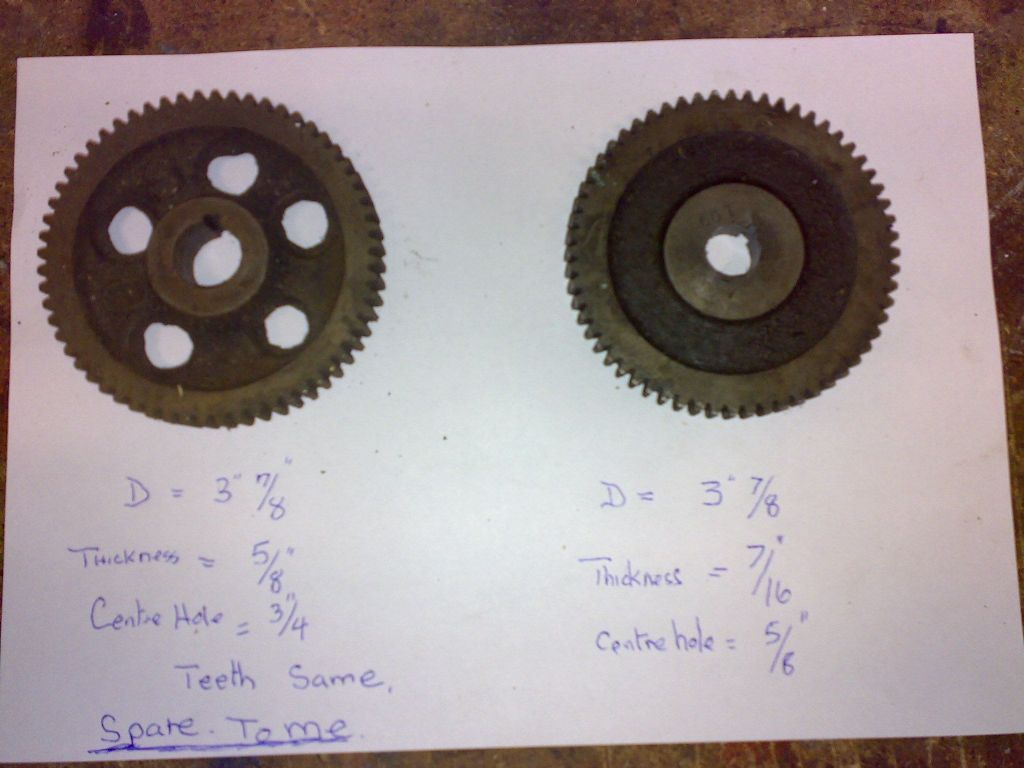
Here we go. I found the original photo my friend sent me about the adapted changewheel. The adapted one is on the left and an original is on the right
Anybody recognise it?
 Edited By John Coates on 21/10/2011 12:47:22 |
| 21/10/2011 12:37:05 |
Posted by ady on 21/10/2011 12:29:20:
Does your barker have a leadscrew reversing gearbox?
Yes it does. The whole lathe needs an overhaul (clean, strip, paint, lubricate) as although it performs well I want it to look "newer" as I'll be keeping it.
Myself and this new owner have ambitious plans to help each other and get our lathes in tip top condition and complete so I'm sure the refurbishment will happen. If we get a basket case to cannibalise then the reversing gearbox can be accessed sooner  |
| 21/10/2011 12:06:58 |
I have a Barker 5 x 24 lathe and have been contacted by another new owner and am trying to help him as his lathe is missing a lot of the change wheels.
I have established that the Barker uses 16 DP for the change wheels. Another model engineer with a Barker adapted a suitable change wheel from his scrap box to make a 60 tooth wheel for me so there are wheels from another lathe that can be sleeved to fit the Barker.
Does anybody know what lathe(s) uses 16 DP change wheels?
Thanks for any help on this one it really will be appreciated
John |
| Thread: Tickets fro Sandown not recieved? |
| 14/10/2011 08:49:06 |
Posted by David Clark 1 on 10/10/2011 21:25:13:
As long as you have a magazine, it is free to get in on the Sunday.
No strings attached
Tickets are in ME4414, ME 4417 and MEW 183.
I really should have read this before getting excited. I thought it was for the MIDLANDS ME exhibition this weekend and have been tearing the house down and generally annoying SWMBO and the kids looking for MEW 183 (which of course is not in the house yet!)
Feeling a bit flat now |
| 10/10/2011 19:25:17 |
| Free entry on Sunday? I'm in Bedford on Saturday night so a trip to the show during the return trip on Sunday could be on if it's free to get in? |
| Thread: Piston ring fitting |
| 10/10/2011 17:27:56 |
| Oh btw, I sympathise with the language. Doing it my first time on a 4 cylinder 550cc engine with four pistons to get into their respective bores with 3 rings on each was fun. I got a piston ring clamp pretty soon after that ! |
| 10/10/2011 17:25:56 |
I use what mick described for my motorbikes - known as a piston ring clamp. Basically a slit steel cylinder which is narrower than the bore when closed together. Put it over the pistons with the rings on, everything is nipped up nice and tight. Lower or raise the cylinder into the bore. Once the closest ring approaches the bore, loosen the clamp and raise it up but keeping the overall circumference just narrower than the bore. As the piston ring enters the bore it will be kept secure as it goes in further. Just continue the process of introducing the piston into the bore, loosening the clamp and moving it up/dpwn the piston.
Main thing to note is that the clamp never enters the bore - it's only there to keep the rings compressed to get them inside the bore as the piston is introduced into the bore. Hope I've explained this enough.
|
| Thread: Old lathe, chuck accuracy |
| 09/10/2011 20:05:20 |
| It is for a central hole through a cylindrical parallel (as per Harold Hall in his MEW series and Lathework a Complete Course WPS book) so it can be secured into a t-nut to set a workpiece true on a milling table |
| 09/10/2011 19:52:39 |
The hole was 8mm dia in 30mm bar for a length of 75mm
David: I've got the George Thomas book so will fetch a glass of malt and give it a good peruse
Mick: I think for cylinder no.2 I will try drilling from opposite ends to meet in the middle and see what that results in
Nick: so what runout should I be aiming for on a 30mm cylinder with finished faces (i.e. not rough BMS)?
Cheers all for the help and information |
| 09/10/2011 18:56:58 |
Posted by NJH on 09/10/2011 18:45:02:
I'm afraid this is very much the name of the game with a 3-jaw.
Regards
Norman
I thought that was the case Norman but as a beginner I just wanted it confirming by somebody more experienced. My suspicions were raised after reading quite a few articles by Harold Hall where after turning in the 3 jaw, any swapping round and the workpiece was then transferred to the 4 jaw and clocked. In terms of clocking the 4 jaw, how accurate should I try to get. Turning and drilling the cylindrical parallels to HH's design I got the workpiece to be somewhere between 0.05 and 0.1mm. Still have two to finish so should I try to be more accurate?
It seems that once I've got to this kind of tolerance once I try another by even the slightest adjustment, the workpiece then goes off in 0.1 - 0.2mm territory. Is there some black art to loosening the jaw and then tightening the opposite jaw to try and reduce to the minimum introducing further error?
John |
| 09/10/2011 16:52:06 |
Sorry to resurrect this thread but I have been having some accuracy issues and searched for chuck accuracy and this thread came up
Is there an inherent inaccuracy with 3 jaw chucks? I only ask as I took my jaws out and cleaned out what I could see with a toothbrush and then put the jaws back in. As I did so I thought about the sequence and wondered whether the scroll acting on the third jaw was "behind" the position of the first jaw as that was fitted as the opening first passed its slot. So when the 3rd jaw is fitted the first (and second for that matter) jaw has already advanced closer to the centre of the chuck.
My inaccuracy was that after turning some bar and centre drilling, I turned the bar around and centre drilled, then I then drilled through and the resulting hole was off centre at the other end. I could see this as I turned it around and put it in the 3 jaw and the hole was noticeably "wobbly". Since then I've been trying to find out if it is the chuck, the mounting, or the setting of tailstock to headstock although I have lined them up using hard centres
Cheers
John |
| Thread: Buying a Lathe |
| 26/09/2011 20:37:40 |
Ronald - what about Wabeco (German) or Ceriani (Italian) ? Have no idea what they are like but they are an alternative to far east
Good luck paduwan !
John |
| 25/09/2011 16:38:51 |
Having been in the same situation two years ago and bought an old 1947 British lathe I think I would buy new. I have to make and mend whereas Myfords would have new tools and accessories. But I don't know what is the best to buy now that Myfords have gone. Others on here are more well versed in the merits of alternative equipment. When I want to move on and buy a new lathe I was wondering what the Ceriani stuff is like and if it is well thought of?
|
| Thread: Spares for Tom Senior M1 |
| 22/09/2011 19:11:49 |
Trawling ebay I found this close to me
I don't have one a Tom Senior but if anyone from further away wants to bid on this and wins I am happy to collect them for you and store them until we can work out a way of getting them to you
I know that sometimes distance and ridiculous postage consequences mean that people who really want bits such as this end up missing out
Just offering to help out any fellow metal basher who really wants this stuff
John |
| Thread: Is this a good tilting vice? |
| 22/09/2011 18:12:40 |
Posted by Harold Hall 1 on 22/09/2011 16:34:06:
I cannot see John how a tilting vice could be used satisfactorily to machine a Keats angle plate, even using a robust vice. See my website
Actually Harold I dug out MEW 161 and read your article. I just need to make a lot of clamps to be able to do it your way, and buy a protractor! Good news is I do have two angle plates
 PS. I do actually find that once I've got things properly aligned, the act of tightening up clamps causes them to go out of alignment. Any fixes for this? Edited By John Coates on 22/09/2011 18:19:23 |
| 22/09/2011 16:11:03 |
Can anyone suggest a better tilting vice please? As mentioned before I already have a Vertex K4 so I can do angles in the horizontal plane.
A good example of what I want a tilting vice for is to be able to machine the V's in a Keats Angle Plate I bought at Harrogate back in May. The castings have sat on the bench whilst I pondered how to machine these and so concluded that a tilting vice would be the most efficient solution.
John
|
| 22/09/2011 12:42:42 |
In need of a tilting vice to allow me to mill V grooves to make various tools from MEW issues as I want to stop using the tilt facility on my mill so I can keep it true
Anyway have found this on ebay and wonder if experienced members on here would consider it a good value item to buy:
I already have a Vertex K4 mill for horizontal rotating angles
Thanks for any help
John |
| Thread: How to tram a mill |
| 16/09/2011 13:31:31 |
Graeme - thanks for that I've saved it in my bookmarks and am busily reading
Steve - having read the article mentioned by Graeme I now realise that the mill can be out of tram in the Y axis. This is why I still post in the beginner's section !!
|
| 16/09/2011 12:44:49 |
Having got through my "crash and burn" learning phase I now seem to be able to approach jobs logically and machine them in a decent sequence to minimise wastage and produce a respectable finished article. Collecting back issues of MEW and reading them is probably helpiong the most
But I think I need to tram the head on my Chester Champion mill/drill. I have just started to make a small workpiece holding plate for my bandsaw. It had cut the plate to size and I was end milling the edges to tidy them up. I tried two different approaches. Firstly I clamped the raised plate flat and milled with the side of a large endmill. Next time I held the plate vertically and used the endmill like a facemill. On this, the way I had clamped it meant the mill could not track fully to clear the end of the cut and it resulted in a strange finish to the piece.
The leading edge of the cut left a very smooth finish but the trailing edge behind the path of the endmill was very rough. I am trying to figure out why this might be but am a bit confused because the mill was travelling along the Y axis which is a plane where the mill cannot be anything but square to the table. The Chester is a round column mill with rotatable head in the X plane. So the endmill could be not true in the X plane but I thought this would lead to different finishes left and right so to speak, not front and back as is the case.
Anyway I need to check the alignment of the milling head and have heard about tramming. Searching Youtube brought up Bogs' tramming device but that will require the purchase of two matched DTI's and some metal for the body. There's no point buying stuff which will get trashed if the cutter is not square to the milling table. I did rotate the mill head to get the 12 degree angle to make a tangetial tool holder so I could have not put it back square (although the fiducial marks are lined up to the best my eyes can establish)
I have an unbranded Screwfix DTI and some 12mm stainless steel from which to make rods to enable me to make some kind of adjustable means of fitting it in a drill chuck to carry out the tramming but thought I would ask on here for any advice before I start in the hope of preventing any cock up I might be able to muster.
respectfully
John |
Magazine Locator
Want the latest issue of Model Engineer or Model Engineers' Workshop? Use our magazine locator links to find your nearest stockist!
Sign up to our Newsletter
Sign up to our newsletter and get a free digital issue.
You can unsubscribe at anytime. View our privacy policy at www.mortons.co.uk/privacy
Latest Forum Posts
- hemingway ball turner
04/07/2025 14:40:26 - *Oct 2023: FORUM MIGRATION TIMELINE*
05/10/2023 07:57:11 - Making ER11 collet chuck
05/10/2023 07:56:24 - What did you do today? 2023
05/10/2023 07:25:01 - Orrery
05/10/2023 06:00:41 - Wera hand-tools
05/10/2023 05:47:07 - New member
05/10/2023 04:40:11 - Problems with external pot on at1 vfd
05/10/2023 00:06:32 - Drain plug
04/10/2023 23:36:17 - digi phase converter for 10 machines.....
04/10/2023 23:13:48 - More Latest Posts...
- View All Topics
Support Our Partners


Shopping Partners
Subscription Offer

Latest "For Sale" Ads
- Reeves** - Rebuilt Royal Scot by Martin Evans
by John Broughton
£300.00 - BRITANNIA 5" GAUGE James Perrier
by Jon Seabright 1
£2,500.00 - Drill Grinder - for restoration
by Nigel Graham 2
£0.00 - WARCO WM18 MILLING MACHINE
by Alex Chudley
£1,200.00 - MYFORD SUPER 7 LATHE
by Alex Chudley
£2,000.00 - More "For Sale" Ads...
Latest "Wanted" Ads
- D1-3 backplate
by Michael Horley
Price Not Specified - fixed steady for a Colchester bantam mark1 800
by George Jervis
Price Not Specified - lbsc pansy
by JACK SIDEBOTHAM
Price Not Specified - Pratt Burnerd multifit chuck key.
by Tim Riome
Price Not Specified - BANDSAW BLADE WELDER
by HUGH
Price Not Specified - More "Wanted" Ads...
Get In Touch!
Do you want to contact the Model Engineer and Model Engineers' Workshop team?
You can contact us by phone, mail or email about the magazines including becoming a contributor, submitting reader's letters or making queries about articles. You can also get in touch about this website, advertising or other general issues.
Click THIS LINK for full contact details.
For subscription issues please see THIS LINK.
Digital Back Issues


Donate

 Register
 Log-in
Model Engineer Magazine
- Percival Marshall
- M.E. History
- LittleLEC
- M.E. Clock

ME Workshop
- An Adcock
- & Shipley
- Horizontal
- Mill

Subscribe Now
- Great savings
- Delivered to your door

Pre-order your copy!
- Delivered to your doorstep!
- Free UK delivery!