Member postings for Les Jones 1
Here is a list of all the postings Les Jones 1 has made in our forums. Click on a thread name to jump to the thread.
| Thread: Tachometer design |
| 31/01/2010 09:53:48 |
Hi Harold, I could probably draw a stripboad layout but it would not be as compact as a PCB. The real problem is it is not worth someone making a PIC programmer just for one project. What is needed is a magazine or company to be prepared to provide the PCB and programmed PIC (Or a kit). I do not think this magazine is set up to provide this service. I could program PIC's for people but buying the components in small quantities is expensive. I used to buy components from Farnell but they have just increased their minimum order value to qualify for free postage from £20.00 to £45.00 so I will not be ordering from them as much. Anyone is welcome to the design and I would have no objection to someone producing kits as a sideline. Les. |
| 29/01/2010 09:49:07 |
Thanks to everyone for their comments. I have concluded that most people that wanted a tachometer have already found a solution either by designing their own or adapting a cycle computer or counter. As a result I do not think it a worthwhile project for the MEW magazine. Les. |
| Thread: Old lathe, chuck accuracy |
| 27/01/2010 09:17:01 |
Hi Mark, Have you verified with a dial gauge that the register on the backplate is running true ? I imagine that this register would be machined on the backplate with it fitted to the lathe on which it will be used on. If I am wrong I'm sure someone will correct me. Les. |
| Thread: To Web Master |
| 26/01/2010 17:57:33 |
Hi David,
Yes it looks like you have fixed the problem. I have not tried adding a test post but the box to enter the text is now there as is the button to post it.
I imagine problems like must eat into your time. I suspect it was not as simple as just hitting a delete button somewhere.
Les. |
| 26/01/2010 14:44:59 |
Hi David, I can see that you have managed to delete what was the third reply. The problem now seems to have moved to just after the last character of my test reply. The bottom slightly darker grey box which normally contains "Message members" etc is missing. This is using IE8. Using Firefox it looks OK Les. |
| 26/01/2010 13:12:22 |
Re Ian S C's report of the problem with the "Old lathe chuck" posting. I could read it (Or part of it.) using Firefox 3.5.7 but not with IE8 or Opera. I tried adding another reply using Firefox. With Firefox I could see this reply but with IE8 I could not. (I did not try using Opera as this is on a different plug in disk drive.) I suspect there is some hidden character in the third reply that is causing the problem. I think if the web master could delete this reply it may solve the problem. Les. |
| Thread: cutting 6BA thread on bronze bar |
| 26/01/2010 11:30:57 |
Hi Tony, Thanks for the information. I have just ordered a 3525 burner and 3486 handle to go with it. I suspect the burner will not fit my existing torch which is over forty years old. Les. |
| 25/01/2010 13:21:22 |
Hi Tony, I wonder which model cyclone burner you have and its heat output? I have been looking at adverts for the Primus cyclone burner torch kit which is claimed to be 7.7 KW output but the picture looks like it is only fitted with a 3.3 KW burner. Les. |
| Thread: Tachometer design |
| 20/01/2010 20:19:21 |
Hi Peter, There is no reason why it should not be used for this purpose. If it was used to sense pulses from the ignition of a single cylinder four stroke engine it could not be set to read the speed correctly as there would be only one pulse every other revolution. It would work with any two stroke engine and with any four stroke engine with any even number of cylinders up to 198 cylinders. I suspect an engine with that number of cylinders could not be built anyway. (I thought I would add that limitation as a joke.) Also it only reads up to 9999 RPM but it could be set to read the speed divided by ten. With a very small change to the firmware it could also be used on four stroke engines with odd numbers of cylinders. Les. |
| 19/01/2010 23:05:56 |
Hi Peter, Sorry but I do not know what an "ICE rev counter " is. At speeds that give over about two pules per second there is averaging over a period of between half a second and a second. This may sound strange but to smooth out readings counts of the number of 0.4 us pulses from one of the timer modules in the PIC are counted until their number exceeds about 0.5 seconds worth. (500000/0.4 = 1250000 ) then the next tine a pulse occurs from the sensor on the spindle the number of 0.4 us pulses from the start of the timing period is divided by the spindle pulses. This gives the average number of 0.4 us pulses per spindle pulse. This is to give a display update every half second where possible. If the pulses from the spindle have a time of more than half a second between them (120 RPM for one pulse per rev) then this is the update rate. I decided that if this time is more than 3 seconds (20 RPM with one pulse per rev) the display should show zero rather than display the last reading until the next pulse was seen. I do not know if this answers your question. Les |
| 19/01/2010 21:15:39 |
Hi Alan, I did use a variable reluctance transducer on my lathe (Made from a coil removed from a low energy light bulb.) with a dual op amp to process the signals but it was not very reliable at very low speeds ( Less than about 50 RPM) I still think the hall effect sensor will be more of a "bolt on and work first time solution.) Les. |
| 19/01/2010 21:06:00 |
Hi John, I do not know anything about Mach 3 software but it sounds like it is working a bit like the "Electronic Leadscrew" project. You should find it using Google etc. I agree that slotted opto devices work very well without any signal conditioning. My lathe (A Chester DB10G also runs a little faster than the indicated speed. Les. |
| 19/01/2010 20:53:27 |
Hi Steve, I have sent a message to you on this forums messaging system with my email address. If you reply with an email address I will send the files to you. Les. |
| 19/01/2010 16:50:49 |
Hi Martin and Steve, The circuit in the picture is only the basics. I think in practice I would put a 5 volt regulator on the board. Also a sense resistor will be required for the hall effect gear tooth sensor that I will probably suggest using. (Allegro ATS642LSHN) This is a two wire device so the voltage across a resistor in series with it has to be sensed. I can not find a source of the thee wire version which would be easier to use. To order the three wire version from Farnell you have to pay the shipping cost from the USA which is high. I have chosen this family of devices as they are very tolerant of their spacing from the gear. As this project is planned for people without access to test equipment I did not want anything that is difficult to set up. I have not yet tested this gear tooth sensor. (I used a hall effect sensor that required a separate magnet on my mill.) One possible use for the spare comparator in the LM393 is to drive an LED so the user can see the led going on and off as the shaft is slowly rotated. On the original unit shown in the picture I used the other comparator as an an alternative input circuit with automatic threshold adjustment. The input signal goes through a high value resistor to the reference input of the comparator with a large value capacitor to ground. (A low pass filter.) Provided the input signal has about a 50% duty cycle the reference input sits at the average value of the input signal. I have avoided suggesting using variable reluctance transducers as their output falls off at low speed. I did use one on my lathe but it required a fair bit of playing round with amplifying its signal and converting its output to clean pulses. I now need to start designing the PCB And test the gear tooth sensor. The software seems to be working OK so if anyone wants to play with it let me know and I will send you the source code and the hex file to program a PIC I hope we are not offending too many people talking electronics on this forum. Les. |
| 18/01/2010 18:11:57 |
Hi David, It does basically measure the time of one revolution and calculate the number of RPM from that. Using it in that mode is suitable when the simplest way to sense rotation is to stick a reflective marker to the shaft. If you then extend this idea and think of two equally spaced markers then it would then read twice the actual speed. So if it is made so that it can divide the reading by two it will display the correct speed. Then extend this idea to many reflective markers but instead of sticking on markers use a hall effect sensor to sense teeth on an existing gear on the machine. So if the reading is divided by the number of teeth on the gear the correct number of RPM is displayed. There will be a single push switch to configure it for the number of pulses per revolution. The way this would be used is to hold the button pressed when power is applied. This puts the unit into setup mode. When the button is released the number of pulses per rev the unit is configured for is displayed. (Value of 1 when the unit is first programmed.) If the button is now pressed again this number increments every 0.7 seconds (Approx.) (Wrapping round to 1 after 99) The button is released when the desired value is reached. To indicate the new value has not yet been saved the top bar of the left hand digit is illuminated. after about five seconds this new value is saved in non volatile memory and the illuminated bar goes out. Power is then removed. When power is re applied the unit comes up in normal mode and the new value of pulses per revolution (Teeth on the gear.) is used in the calculation. I have chosen to allow for betweenone and ninety nine pulses per revolution but this could be changed up to easily up to 255 if required. Using the unit for high speeds and a large number of teeth on the gear reduces the accuracy. For example at speeds near 10000 rpm with a 99 tooth gear the error would be nearly one percent. I think this would be good enough for machine tools. Also I think that worst case situation is unlikely to occur. Les. |
| 18/01/2010 15:41:27 |
Hi Lawrie, The idea of this design is to avoid mounting an encoder disk on the machine. Using it in one pulse per revolution mode only involves putting a reflective marker on a convenient part of the spindle and fixing a reflective opto sensor close to it. (I just glued a piece of baking foil onto a pulley on my drill press.) Using it in its multi pulse per rev mode just involves placing a hall effect gear sensor near to an existing gear on the shaft. By the way I got caught out using an encoder taken from an HP500C printer. Testing it on the bench I thought it gave 500 pulses per revolution. When I mounted it on the end of the leadscrew on my mill I found it was 504 pulses per revolution. This was to use it to drive a digital readout. Being a strange number of pulses per revolution made it useless for the purpose. One thing I forgot to comment on in my last message suggesting contacting Dave Clark. I thought he may have posted a reply with his views. He may be waiting to see what other readers comments are first. Les. |
| 18/01/2010 11:16:12 |
Hi All, All the methods suggested are good when the situation suits. Using the frequency meter to count 60 pulses per rev is ideal if it is easy to fit a disk with 60 holes and optical sensor or a 60 tooth gear and hall effect gear tooth sensor. The cycle computer I think is the cheapest method if it can accommodate the speed range required. The problem mentioned about mounting the magnet can be eliminated by using a reflective optical sensor and signal level converter. The first rev counter I made for my lathe used the frequency meter method. The lathe had a 45 tooth gear on the end of the spindle so all that was required was to count the number of pulses in 1.333 seconds. (60 divided by 45) The mill had a gear with 34 teeth which would have required measuring the number of pulses in 1.765 seconds (60/34) I considered that this would be too slow an update rate so I modified the design to get a pulse of each edge of the tooth so this brought the sample time down to about 0.8 seconds. On various forums there had been questions about rev counters for use with one pulse per rev. I also wanted a rev counter on my drill press which did not have any gear teeth to sense. For this I needed the method that must be used by a cycle computer which is to measure the time of one revolution and calculate RPM from that. I actually counted the number of 0.4uS pulses that occurred in one revolution and divided this into 150000000 which is the number of 0.4 uS in one minute. By adding some code to divide the reading by the number of pulses per rev sensing any number of pulses per rev can be used. I then thought of a way to enter the number of pulses per rev using one push button connected to a spare input on the PIC chip. Hence the question about interest in the design. Yesterday I have got the unit basically working but now need to test that there are no problems with any pulses per rev setting at any input speed. (Overflow of numbers in the calculations or other problems I have not even thought of.) I would be interested in information on the cycle computers in terms on the maximum and minimum wheel sizes they can be configured to work with and the maximum speed they can display. (Also the number of digits in the display.) As the method of operation of my design is basically the same as a cycle computer if they can cover the required speed range then my design is redundant. I think the components for my design will cost between £6 and £10 plus a PCB, box and power supply. I think someone asked about calibration. This is not required as the time measurement is controlled by a crystal whose accuracy is quoted in parts per million. Steve, I am not sure about how the Quasar design works as though the give the schematic they do not give the integrated circuit numbers. I SUSPECT that it uses a "charge pump" to convert frequency into voltage then displays that voltage as RPM's Sorry all about the length of this reply. Les. |
| 16/01/2010 18:41:50 |
Hi Martin (C), I have only read a few copies of MEW I have only bought it when I have seen that it contains an article of interest to me. The spark erosion machine sounds interesting. I experimented with it in the mid 1960's without much success. Here are some pictures of the original version which is only for one pulse per revolution. The only difference in the hardware for the version that supports different numbers of pulses per rev is the addition of a push button switch. The rest will be done by re writing the firmware. 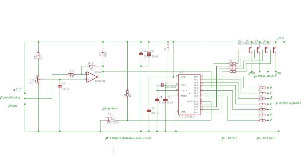 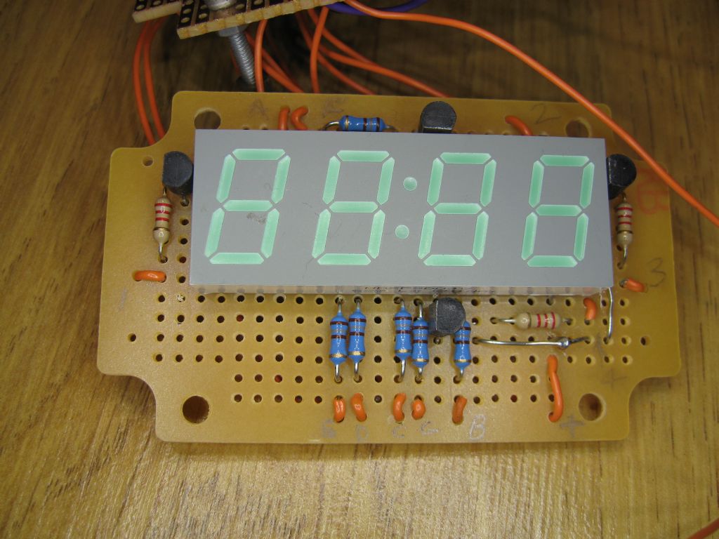 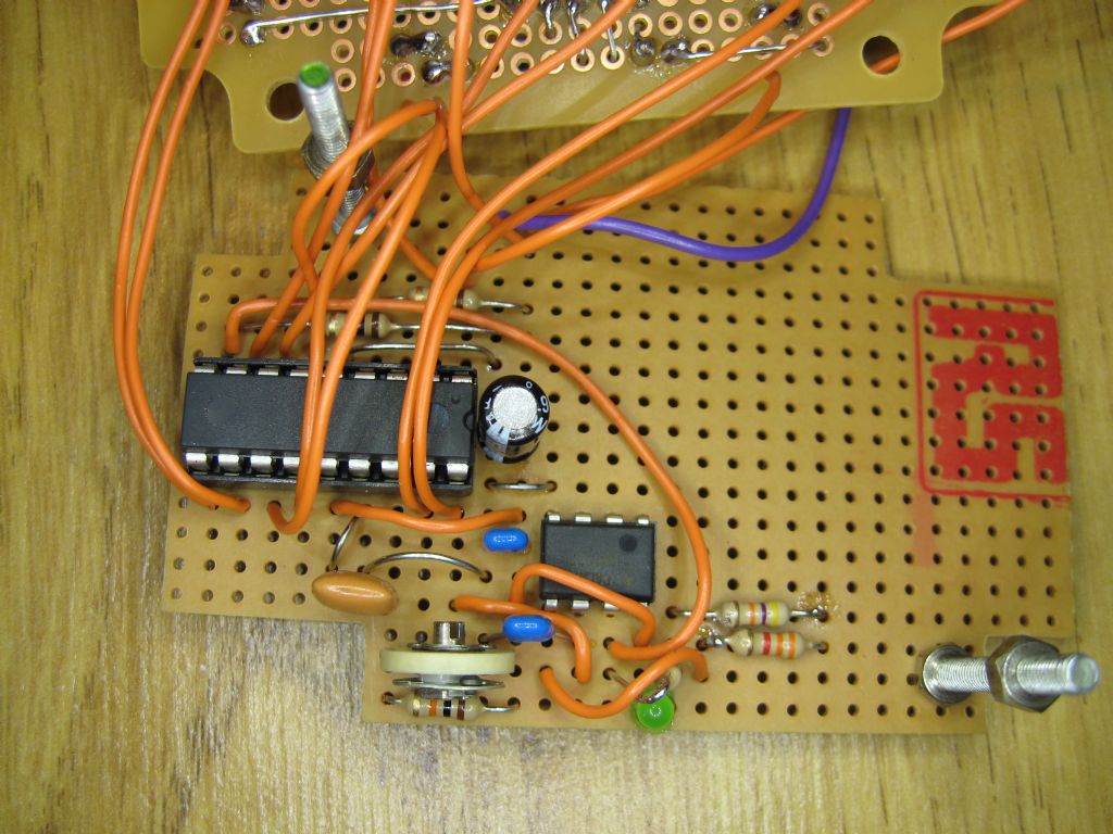 I do not think the schematic is readable but it should give an idea of how simple the circuit is. Les. |
| 16/01/2010 15:08:33 |
Hi Martin, I have put the design that this tach will be based on on one of the Yahoo technical forums (X series mills I think) That one is for one pulse per rev. It basically measures the time of one revolution and then calculates the RPM from that. All I plan to do is to add a single push button to enable the number of pulses per rev to be set. The plan is this. To enter setup mode power up the unit with the push button pressed. When it is released it will be in setup mode and will display the current pulses per rev value. Pressing the button again will cause this value to increment at a rate of about one per second. when the required setting is reached the button will be released. About 5 seconds after the button is released this value will be stored to EEPROM. (Non volatile memory.) The unit is then powered off to get out of setup mode. When it is next powered on the new value in EEPROM will be used in the calculation. The circuit is very simple using a PIC16F628A, a four digit LED display, a 20 Mhz crystal, four transistors and a few resistors and capacitors. Having to building a programmer I think would put people off which is why I thought of the electronics magazine route. I was not thinking of the payment side just a way of making it easy for a non electronics person to build. I just built mine on stripboard. (Or Veroboard as it used to be called.) I will wait and see what others think before deciding which way to proceed. Regards Les (Ormskirk Lancs.) |
| 16/01/2010 12:45:14 |
| Hi All, I have built tachometers for my lathe mill and drill press in the past. The design was governed by an easy way to sense the rotation and what bits I had lying around at the time. I was wondering if there would be any interest in a tachometer that could cope with between 1 and 99 pulses per rev. If there was I do not know if it would be best to try to get the design published in "Model Engineers Workshop" (Where it would more likely interest readers.) or in "EPE" electronics magazine who are more set up to provide printed circuit boards and programmed PIC's One pulse per rev is useful if there are no gears in the drive train. One pulse per rev can be sensed easily with a reflective marker and optical sensor. If there are gears in the drive train a hall effect gear tooth sensor is easy to use. The display would be a four digit LED display reading from about 30 RPM to 9999 RPM Regards Les (Ormskirk Lancs.) |
Magazine Locator
Want the latest issue of Model Engineer or Model Engineers' Workshop? Use our magazine locator links to find your nearest stockist!
Sign up to our Newsletter
Sign up to our newsletter and get a free digital issue.
You can unsubscribe at anytime. View our privacy policy at www.mortons.co.uk/privacy
Latest Forum Posts
- *Oct 2023: FORUM MIGRATION TIMELINE*
05/10/2023 07:57:11 - Making ER11 collet chuck
05/10/2023 07:56:24 - What did you do today? 2023
05/10/2023 07:25:01 - Orrery
05/10/2023 06:00:41 - Wera hand-tools
05/10/2023 05:47:07 - New member
05/10/2023 04:40:11 - Problems with external pot on at1 vfd
05/10/2023 00:06:32 - Drain plug
04/10/2023 23:36:17 - digi phase converter for 10 machines.....
04/10/2023 23:13:48 - Winter Storage Of Locomotives
04/10/2023 21:02:11 - More Latest Posts...
- View All Topics
Support Our Partners


Shopping Partners
Subscription Offer

Latest "For Sale" Ads
- Reeves** - Rebuilt Royal Scot by Martin Evans
by John Broughton
£300.00 - BRITANNIA 5" GAUGE James Perrier
by Jon Seabright 1
£2,500.00 - Drill Grinder - for restoration
by Nigel Graham 2
£0.00 - WARCO WM18 MILLING MACHINE
by Alex Chudley
£1,200.00 - MYFORD SUPER 7 LATHE
by Alex Chudley
£2,000.00 - More "For Sale" Ads...
Latest "Wanted" Ads
- D1-3 backplate
by Michael Horley
Price Not Specified - fixed steady for a Colchester bantam mark1 800
by George Jervis
Price Not Specified - lbsc pansy
by JACK SIDEBOTHAM
Price Not Specified - Pratt Burnerd multifit chuck key.
by Tim Riome
Price Not Specified - BANDSAW BLADE WELDER
by HUGH
Price Not Specified - More "Wanted" Ads...
Get In Touch!
Do you want to contact the Model Engineer and Model Engineers' Workshop team?
You can contact us by phone, mail or email about the magazines including becoming a contributor, submitting reader's letters or making queries about articles. You can also get in touch about this website, advertising or other general issues.
Click THIS LINK for full contact details.
For subscription issues please see THIS LINK.
Digital Back Issues


Donate

 Register
 Log-in
Model Engineer Magazine
- Percival Marshall
- M.E. History
- LittleLEC
- M.E. Clock

ME Workshop
- An Adcock
- & Shipley
- Horizontal
- Mill

Subscribe Now
- Great savings
- Delivered to your door

Pre-order your copy!
- Delivered to your doorstep!
- Free UK delivery!