Member postings for Ramon Wilson
Here is a list of all the postings Ramon Wilson has made in our forums. Click on a thread name to jump to the thread.
| Thread: Stuart Twin Victoria (Princess Royal) Mill Engine |
| 13/07/2022 22:10:19 |
No, that's new to me Jason but yes just the kind of mod I had in mind. I often wished that I'd also taken the time to make the cylinders with feet rather than the original method too - agh, hindsight is twenty twenty vision don't they say? Just a thought Doc but somewhere I'm pretty certain I still have the form tools I made for the cross head spacers - HSS and form ground they're yours if you'd like them. |
| 13/07/2022 21:32:08 |
Doc, I made my Twin Vic many years ago. Apart from a small twin oscillator it was my first engine built and successfully finished - the first, a ST Compound Launch engine, was doomed from the outset due to lack of knowledge and skill at the time. The exact date I'm unsure of but I do know I bought basic Twin Vic castings along with the drawing (which I still have somewhere I think ) when Stuart Turner traded from Henley and before they had the big hike in prices. Late seventies/early eighties perhaps? I only bought the minimum of cast iron parts and not all of them at that - as best I can recall just the bed plates, cylinder blocks, piston rod end cover and valve chest and of course two flywheels. Everything else was made from scratch including those bearing pedestals which I'm pretty sure I made from mild steel. The bearings were from bronze and split. I always thought that the bearing housing make up was too 'thin' and were I to do another would bond on a plate to the sides of the bed plates to increase the potential width to mount wider bearing housings. I have no recollection of changing the design height of the bearing. The original model engine was based on a quite small industrial engine that was found in an old premises I believe. Stuarts twin version was their idea of a potential engine that may have been offered by the manufacturer. Indeed quite a few did do this and I have a few reprints of old catalogues that support this possibility. To use the parts to make a representation of a larger, heavier (full size) engine however there are areas that have to be improved not least in stature - the bearing supports are one. I often looked at the engine in hindsight and wished I had done that. I've already mentioned to you the flywheel grooves - if done to print they are well over size for the size of engine but if done smaller and too many are put in then you increase the scale proportionally to the rest of the engine too - the engine becomes much larger and some areas are then truly undersized. As Jason suggests, personally I would write the castings off at this stage - keep them for something else perhaps. Make new pedestals/housings from mild steel or the bit of cast you have left from the covers and make the bearings from bronze - even brass will do but bronze would be better. Using the yellow coloured cast bronze and not the pinkish drawn bronze will ease manufacture considerably. Without looking I'm not sure what those drawings say about the crank relationship but I know I initially made it with the cranks at 180 degrees. Why I do not recall. When I first exhibited it at the Forncett Industrial steam museum however the owner commented on that irregularity immediately. Suitably chastised, once home it was immediately stripped it down and the crank shaft changed to the correct 90 degree relationship. In the builds since that time then I have tried to incorporate full size characteristics where possible. Hope that helps ease the confusion Regards - Ramon Edited By Ramon Wilson on 13/07/2022 21:36:05 Edited By Ramon Wilson on 13/07/2022 21:36:19 |
| 13/07/2022 17:27:10 |
Posted by JasonB on 13/07/2022 17:09:35:
Put them in a cupboard and start from scratch, those look to be 7/8" ctr height ones not 5/8" that you want. It will be easier than trying to cut down and reassemble what you have.
Well yes, can't disagree with that but you did ask about the castings! Much easier to make two pedestals and caps from scratch in mild steel or cast and then make split bearings to suit, fundamentally as described above. I have quite a few images covering the latter from a previous thread if you want Here's my version on the Twin Vic
|
| 13/07/2022 17:13:14 |
Hi Doc, good to see you moving forward.
First thought is a note of caution as after the cast iron the gunmetal is a considerably softer material and can distort and will easily with little pressure. It's important to bear in mind good firm 'clamping' - chuck, clamps or vise with minimum pressure. Personally I would do near as you suggest for the initial ops but only skimming the top and lower surfaces of the pedestals the absolute minimum to clean up bringing them as near parallel as you can Do the same with the mating surface of the top cap. Accurately measure the distance of the pedestal top face from the lower face on both parts and make a note of it. Tin each part with soft solder and solder the two parts together. Set in the mill vise with the lower face to the fixed jaw and hole face pointing upwards. Move to the solder line (the dimension you noted down) and the sideways centre of the casting by eye. Drill, bore and ream the holes for the crankshaft. Ignore all other faces at this stage. Make up an expanding mandrel in the lathe and mount gently to face the two outer bearing boss faces. Don't be tempted to do any other turning at this stage as you may spring the joint apart. Transfer to the mill and still on the mandrel gently mill the lower face relative to the mandrel at the same setting for both blocks. Rotate 180 degrees and drill and tap for the bolts on the centre line - take the tapping drill just into the lower bearing pedestal. You can now handle this with more firmness ref clamping pressure so- Fit bolts and back in the lathe do the remaining turning to bring the bosses true then hold in the mill vise lower face uppermost to drill the main hold down bolt holes. Do the oil hole etc and finally heat to break apart. Gently lap the solder off on some wet and dry on a flat surface. Gunmetal needs really freshly ground edges on any tooling as it is easily 'pushed' rather than cut by even the slightest dull cutter ie one previously used on steel. By milling the faces to the bore it's much easier to measure to the mandrel and as all ops are done from the mandrel everything thing will be square. The one thing I would not do - under any circumstance is bore this component using a four jaw chuck to previously machine faces. The potential for distortion is high, the accuracy of chucking two parts the same doubtful at best.
That's my take - no doubt others will differ so listen to all before you make your mind up but my caution on machining gunmetal stands - very easily spoilt in a split second
Good luck with it
Ramon Edited By Ramon Wilson on 13/07/2022 17:15:11 |
| Thread: Boll-Aero .49 Glow Engine |
| 12/07/2022 16:03:06 |
Wow Keith, that's come out well Really looks the part. I can well imagine the noise - takes me back to when we flew with 35's on open exhaust all the time. Lovely result indeed. Hope you are well Tug PS as an aside I used oil filled nylon for my first rotor in the Racer only to find out it can distort under rotational/centrifugal loads! Made all others following from Tufnol which is a much better material for a rotor but the nylon one remains and still works |
| Thread: Filing rest - hardened guides ruining files |
| 12/07/2022 07:55:18 |
Posted by JasonB on 12/07/2022 07:17:43:
I don't use a rest but do leave filing buttons soft. Question for the Hardened side of the fence, what colour do you temper them to as I don't see this being mentioned just "hardened" Hardened buttons should be fixed - soft should be free to roll, if they don't, and without a degree of caution the file can do its work on the button too and the part can easily be spoilt. If hardened rollers/buttons roll then the file will wear quickly as opposed to skating across the surface when fixed. Very easy to tell when the two faces contact. I have made them soft but ensuring they roll freely is often more time consuming than hardening Like Bernard been using hardened buttons for far longer than I care to think but never bother to temper them - a quick quench and use straight away - their purpose is usually a one off and simply not worth doing. Never throw them away of course - they might get a second or more go in the future. I made a small filing rest with hardened (rolling) rollers many years ago - spoilt a couple of files before loctiting them in place. Don't use it often I agree but it works well when I do.
Tug
|
| Thread: turning small square stock |
| 10/07/2022 21:56:07 |
Steve - quite late in my model engineering days I bought myself a self centering 4 Jaw chuck more at the time as 'something to buy' at a show rather than an actual direct need as I had both 4" and 6" 4 jaw ind. chucks. It very quickly became my first choice chuck and has replaced the years old but still serviceable 3 jaw Myford as permanent chuck in use. Round, square and hex it's something that makes the kind of op you are doing a doddle and, had I realised it's versatility and usefulness, is something I would have bought, many years before I did, . Though not an alternative for an independent jaw it's a very useful additional bit of kit that will see much use. Maybe worth considering?
Tug |
| Thread: Stuart Twin Victoria (Princess Royal) Mill Engine |
| 10/07/2022 14:19:40 |
Hate to put my safety hat on Doc but that's exactly what I meant too - you'd have found it had it hit you in the face The idea that the video shows is indeed a quick way to ensure 5 sides of a square or rectangular block are true to each other and is one tried and endorsed but both Jason and I are trying to get you to see that no matter how good the surfaces look when sawn the chances of them being parallel are pretty slim. Had you have taken a skim over all side faces of the block beforehand the next time you pick it up it will pop straight in the vise - to my mind it's a bad habit to get into and one which will eventually lead to a decision 'not to do that again' but then of course by then something will be truly spoilt - workpiece, machine or flesh - potentially all three together. Each time you grip something like that in the vise - packing or not - you will be straining the vise beyond it's design parameters at the very least. Just saying!
Best - R
Edited By Ramon Wilson on 10/07/2022 14:20:41 |
| 10/07/2022 09:05:32 |
Posted by Dr_GMJN on 09/07/2022 23:28:39:
Thanks Ramon. By the way, rewinding a bit, this was the basic principle I was using to square the block (although obviously my technique to grip the sawn faces was wrong): And to be fair in the end it worked ok. I agree but your crab could have been much worse and caused more damage than it did. I was made aware of this method to quickly and initially square a block only recently and yes it's an excellent way to do it, when the work design warrants it, but as you've found, the block needs to be faced first in order to be held securely to do it. 'Blocking out' - to my mind is something that should always be considered as a first op before machining to dimension begins - once again you 'know' it's square if you do. I would think that virtually everything that I've made from scratch has always begun life as such. Here's an example - this could have begun from a sawn off block straight in the lathe but blocking first gave firm reference faces - the turned face and bores the first datum finished to dimension from which all else is referenced to - much more difficult to create if if the block was still sawn
Here's the result
I'm now off to put some more into the F4 - enjoy your day Best - R |
| 09/07/2022 18:40:04 |
Posted by Dr_GMJN on 09/07/2022 18:31:38:
Ramon, the oilers will have sealed caps, so remove the cap, add oil, replace the cap. They won’t be open ‘drip’ oilers. Alternatively, a short bolt could be used (but wouldn’t look as nice). The throttles will be as per the plans - butterfly valves. I suppose the advantage of these is that they are to a degree balanced. The oiler on mine is that point on the top of the central manifold. I had originally intended to fit a working oiler plumbed to that point but that never happened. The engine was displayed a lot, originally on steam then on air. Oiling was carried out by removing the plug, squeezing a slug of steam oil in from a syringe and replacing the plug. On steam that would last quite a while but virtually all day on air. When I have run my other engines as such I just squeeze the oil in to where the airline enters. I always use steam oil even on air - works well without emulsifying.
|
| 09/07/2022 18:32:45 |
I used reduced spindle speeds today, and had a much better experience! Ill carry on with this I think, and fit the Vulcan in when I can. Problem is I airbrush in the same vicinity as machining, so I have to vacuum/degrease everything before risking a spraying session. Yes, I was referring to your previous images and not those on the covers. The main time I use paper is for when a part has minimal clamping pressure either due to its set up up or when I don't want to use to much pressure on a weak part. The increase in grip per se can be eased as it makes a considerable difference - relative to the clamping pressure - in such a situation I'm fortunate in having two spaces to keep the two separate but often that in itself raises 'conflict' - which one to be in!
Which ever way you go - enjoy it |
| 09/07/2022 18:23:52 |
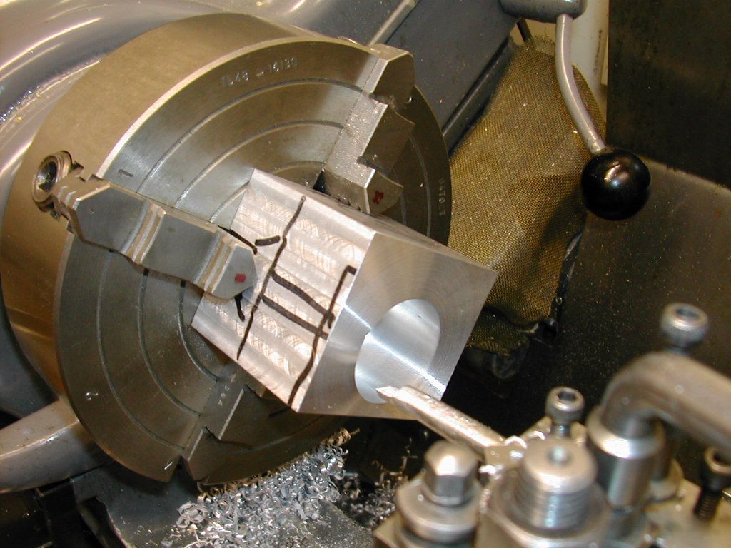
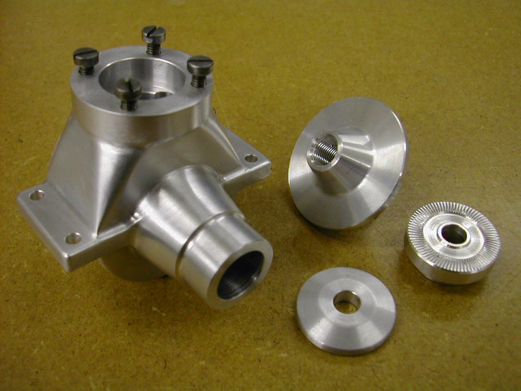
As an aside Doc - how are you going to bring the 'steam' (air) in if you are mounting oilers on the steam chest. Do you have an inlet in the side of the valve chest that's out of sight in those images Most large stationary engines had steam directly into the top face of the cylinder where a larger surface are allowed for a bigger inlet valve Whilst there would no doubt be oilers mounted on the steam chest the steam inlet would usually be there too. This is how I did mine if it's of use The throttles for the governor are within the blocks. I didn't make butterfly types but rotary ones similar to a model aircraft engine carb. Obviously if it's a twin set up unlike a compound the governor should control both cylinders
Hope that's of use |
| 09/07/2022 18:09:59 |
Hah! looks like our posts crossed! Very nice result Doc, I can well appreciate the work and effort you have put in to get there, they certainly look the business Regards - R |
| 09/07/2022 18:05:47 |
Well you got there in the end Doc and that's what matters but I will say you would have been a difficult apprentice to teach Holding directly on sawn surfaces in a vice for milling even with paper is an accident or a ruined part waiting to happen. It's not just the part either, self safety and the damage to the machine and cutter needs bearing in mind too. 'Catching a crab' as we refer to it around here when you least expect it is one thing (and yes I've had a few over the years) but working in a manner likely to create the situation is not really good practice. Your enthusiasm to get on reflects my own in early days but the best advice I had from a sage old machinist at the time was "You need to slow down to speed up" I guess that's you near back on the Vulcan now then. The Phantom is going well but a trip to Hannants is called for before the next phase can get going Stay well
Best - R |
| 09/07/2022 14:08:37 |
Good post Jason and yes that was a long time ago. The terminology has changed some too but to this old 'dino-sore' a centre cutting 'endmill' is still a 'slot drill' - three flutes or more Regarding actual cutter size and method I would hazard a good guess that 90% of my machining is done as you say - with a slightly higher RPM, lighter cuts and a high-ish hand fed feed rate but not, I stress, on cast iron. To boot most of it is done with HSS 6mm FC3 throwaway cutters too. This puts much less strain on the Linley mill though it's sturdy enough to take more of course. Coatings are another matter but again I don't think the benefits - on home based basic kit - outweigh the extra cost. That said one of the best wearing cutters I used both at work and home was a Presto 6mm TiN coated FC3. At work we would only use Clarkson, Dormer or (agh! name escapes me - sign of the times I'm afraid **) throw away cutters but I was convinced by a sales rep to try this Presto brand. Well the small diameters lived up to 'expectation' and had but a short life but the 6mm' s just went on and on, far in excess of anything we got out of Clarkson and others. The only coated cutter, I would say, that I used personally to have shown any benefit over non coated. This is long before CNC appeared in our workshop so Bridgeports only! I guess the problem is now, one of manufacture. I bought some TiN coated cutters some time back from ARC but they do not perform as well as I'd hoped for I'm afraid to say - they very quickly wear and soon begin to rub. One thing that soon became apparent - there are always easier ways to do most things but it's best to assume there are few shortcuts! They virtually always end in disaster . Best - R
** Osborne? Edited By Ramon Wilson on 09/07/2022 14:09:42 |
| 09/07/2022 12:48:20 |
Yes Hopper, the ready availability of carbide tooling has certainly brought a new dimension to the home workshop though perhaps not always for the best. Though I have various carbide cutters to use they only get used on rare occasions when the task really demands it. HSS tooling is a much more versatile material to use in the home work shop as once past their useful life they can be reclaimed even by hand far more easily than carbide can - not to mention being easily converted into further useful tooling if broken. I'm at the end of my machining days now and whilst I do appreciate that things have moved on (considerably) as you say 'basics are basics'. I've always offered my thoughts on being the best (as in easiest) way to achieve something bearing firmly in mind the limited kit that's at the disposal of most home users. Yes they are those with some lovely kit - even industrial quality - to call on but I'm not one of them so have always 'cut my cloth' etc to what I have in my workshop and even my limited resource can be a lot more than most for some. I'm not saying that available information should be ignored, just that it isn't always necessary to get the job done to a satisfactory outcome.
Best R
|
| 09/07/2022 11:39:57 |
Doc - not wishing to pre-empt Jason but like you I began my engineering life as an amateur (1972 ish) And like you I struggled with feeds and speeds but around 1980 I gave up my offshore career and retrained as a milling machinist. The first thing I was taught was how to square a block in a vise - just as Jason shows. Cut surfaces cannot be regarded as ideal to be gripped in a vice and as someone else has said copy paper is all that's required behind one face - next to the fixed jaw. Card, even thin card will compress and is not advisable. The second thing that really was a game changer was to be taught about the varying cutting speeds of various materials. At the time I wrote this down in a little note book - it's still on my shelf and occasionally still gets referred to. It might not be 'au fait' with modern thinking and advise but it works and works well - not only for industrial use (at that time) but now - in the home workshop on the small kit most of us have at our disposal
The formula can be reduced to CS x 4 over dia of cutter (or work if on a lathe) which will give the near enough optimum speed Now I realise much has moved on over the last forty plus years but this has stood me for all of that time - yes I do possess several of the 'posey' manufacturers booklets that show optimum speeds and feeds all of which are the optimum for industrial machines in an industrial environment. I have spent many years in front of a lathe, mill or grinder at work but never felt the need to bring that 'pace' into my home workshop. Most newbies to the hobby make two fundamental mistakes because of lack of knowledge - either they run largish cutters - say 6mm upwards - too fast and small cutters far too slow. The info on the page above sorts that out immediately. Finally good cast iron will machine with ease if the speed of the cutter is right - much better to start slow and move up than the other way round. If the machined surface has a shiny glaze to it it's too fast, a nice uniform matt is when you have it right.
Hope that helps a little more.
Edited By Ramon Wilson on 09/07/2022 11:42:18 |
| 01/07/2022 07:28:02 |
'Hyper detailing' eh Doc? A very nice result indeed It will be a few months yet before I follow your lead but the Phantom grows steadily. Keep it coming Best - R
|
| 24/06/2022 07:33:14 |
Nice result and plus one for the fillet. It looks like you were using a carbide EM which precludes the idea but if you use a HSS cutter you can radius the teeth by hand on a bench grinder to give a radius. I have a tin of several such modified cutters - very useful at times All looking good Doc - hope that second one goes as well |
| Thread: Amadeal VM25L R8 Milling Machine |
| 23/06/2022 19:09:05 |
I have an Amadeal too - very satisfied. You will soon learn it's capabilities but 'start easy and work up' rather than down! Strongly advise you follow the advise of all the comments but contrary to Jim Nic I would say that if you do get a vise with a rotating base then you have an 'attachment' that when wanted is an absolute godsend. I agree - it's not used very often but when you want to swivel your vise you can guarantee the bolt holes wont align with the tee slots at the angle required. Yep you can clamp the vise down but if you have the base that's so much simpler. Remove it as soon as you get it and store it under the bench - the vise will be much more rigid without it and less high Enjoy yourself Tug |


.jpg")
Magazine Locator
Want the latest issue of Model Engineer or Model Engineers' Workshop? Use our magazine locator links to find your nearest stockist!
Sign up to our Newsletter
Sign up to our newsletter and get a free digital issue.
You can unsubscribe at anytime. View our privacy policy at www.mortons.co.uk/privacy
Latest Forum Posts
- *Oct 2023: FORUM MIGRATION TIMELINE*
05/10/2023 07:57:11 - Making ER11 collet chuck
05/10/2023 07:56:24 - What did you do today? 2023
05/10/2023 07:25:01 - Orrery
05/10/2023 06:00:41 - Wera hand-tools
05/10/2023 05:47:07 - New member
05/10/2023 04:40:11 - Problems with external pot on at1 vfd
05/10/2023 00:06:32 - Drain plug
04/10/2023 23:36:17 - digi phase converter for 10 machines.....
04/10/2023 23:13:48 - Winter Storage Of Locomotives
04/10/2023 21:02:11 - More Latest Posts...
- View All Topics
Support Our Partners


Shopping Partners
Subscription Offer

Latest "For Sale" Ads
- Reeves** - Rebuilt Royal Scot by Martin Evans
by John Broughton
£300.00 - BRITANNIA 5" GAUGE James Perrier
by Jon Seabright 1
£2,500.00 - Drill Grinder - for restoration
by Nigel Graham 2
£0.00 - WARCO WM18 MILLING MACHINE
by Alex Chudley
£1,200.00 - MYFORD SUPER 7 LATHE
by Alex Chudley
£2,000.00 - More "For Sale" Ads...
Latest "Wanted" Ads
- D1-3 backplate
by Michael Horley
Price Not Specified - fixed steady for a Colchester bantam mark1 800
by George Jervis
Price Not Specified - lbsc pansy
by JACK SIDEBOTHAM
Price Not Specified - Pratt Burnerd multifit chuck key.
by Tim Riome
Price Not Specified - BANDSAW BLADE WELDER
by HUGH
Price Not Specified - More "Wanted" Ads...
Get In Touch!
Do you want to contact the Model Engineer and Model Engineers' Workshop team?
You can contact us by phone, mail or email about the magazines including becoming a contributor, submitting reader's letters or making queries about articles. You can also get in touch about this website, advertising or other general issues.
Click THIS LINK for full contact details.
For subscription issues please see THIS LINK.
Digital Back Issues


Donate

 Register
 Log-in
Model Engineer Magazine
- Percival Marshall
- M.E. History
- LittleLEC
- M.E. Clock

ME Workshop
- An Adcock
- & Shipley
- Horizontal
- Mill

Subscribe Now
- Great savings
- Delivered to your door

Pre-order your copy!
- Delivered to your doorstep!
- Free UK delivery!