Member postings for Raymond Griffin
Here is a list of all the postings Raymond Griffin has made in our forums. Click on a thread name to jump to the thread.
| Thread: PGK's 1" Minnie |
| 10/04/2016 18:14:26 |
Addendum to my recent post. I made a real faux pas with my Minnie boiler. Once it was completed, but before the side stays were in place I did a hydraulic pressure test for leaks, as recommended by Mr Mason. He suggests 10lb/sq. in. Me, being clever, thought that a bit more pressure could be more revealing. So I took mine to about 15lb/sq.in: lo and behold, the internal and external side panels of the fire box puffed out, like trumpeters cheeks. It was a miserable job getting them back to parallel and straight using clamps. I think that this intermediate test could be left out, as there is a full pressure test when the stays are in place. Leaks can be rectified at this stage. |
| 10/04/2016 16:39:37 |
So good to see the work of other Minnie builders. Pgk, I have made other boilers over the years, but none as complex as this one. My previous efforts have been in water tube boilers for model boats and stationary engines. I followed the guidelines in the book by Mr Mason for much of the construction of this boiler; with a few strategically placed copper rivets to hold assemblies together. My silver soldering is based on much of the existing literature. There is a helpful series written by Keith Hale of CUP alloys called “Overcoming difficulties in silver soldering” in the “Model Engineering in Miniature” magazines of November, December 2015 and January 2016. 1. I try to get joints that are not too tight or too large. Too tight restricts capillary flow: too large, hard to fill with expensive silver solder 2. I clean all my copper pieces in acid before each heating cycle. I use nitric acid, diluted to about 5% from the 25% stock sold by our local hardware shop: adding acid to water, of course. Copper immersed in the dilute nitric acid will become clean in seconds. I learnt to use nitric acid for silver soldering in metalwork classes, at school in the 1950’s. However, all the safety precautions for using strong acids must be followed rigorously. I clean mine in the open air as obnoxious/toxic fumes can be evolved if care is not taken. Nitric acid will not normally be available in the UK, so dilute sulphuric acid or citric acid can also be used. I do wonder if the acid treatment is a bit over the top, as in reality only the areas to be soldered need to be bright copper. This can easily be done with wire wool. The flux should take care of any local oxidation from heating. 3. The size of torch used is important even in a small boiler such as this. I found that the Sievert 3491 (3.1Kw) burner normally used for heating smaller jobs could not provide sufficient heat quickly. So changed to a 2942 (26Kw) burner used with an extension tube, as it gets very hot. The larger burner did the trick for me; it brings the job up to temperature quickly and easily. 4. I used silver solder with two melting points as normally recommended for work of this nature. I used No. 438 (650°-720° 5. I find some form of insulation around the work essential when heating. Coke is mentioned a lot in older literature; but I don’t know where you would get it. Anyway, the fumes from the hot coke could be a bit daunting. I have two insulation blankets from CuP alloys at £10.80 each they are cheap and for me, indispensable. One is kept whole and wrapped around the boiler; the other is torn into pieces and stuffed into large orifices to prevent the circulation of cooling air through the boiler. Good luck with your soldering. Brian, your gears look really nice. Do you have any tips on getting them to mesh nicely? I am just starting on the bearings for the shafts. Bonne courage, to all Ray |
| 09/04/2016 16:51:29 |
Hi, it looks as though there are a number of us making the 1” Minnie. I seem to be a little ahead of pgk pgk, in that my boiler is completed, and I have pressure tested it to my satisfaction. I have a similar problem of boiler inspection. I live in the South of France, so access to a boiler inspector is out of the question. I belong to my local Model Club, but am the only constructor in steam. I find boiler making irksome, and can fully understand anyone buying one. I wonder what percentage of these models are made just for the pleasure of construction, and in fact never envisaged for fires and steaming. I have just fitted the horn, spectacle, and back plates, and was pleased to be able to purchase them as laser cuts from Blackgates. Laser cut material is a great saving in precious workshop time. Shafts placed in the pre-cut bearing holes are parallel, so no fear of misalignment. My only worry is that the centres may not be perfect for the gears. Mr Mason emphasises clock making methods to ensure correct meshing of the gears. I will cross that bridge when I get there. Three photos of work so far. Happy constructing, to pgk, and other Minnie builders.
|
| Thread: Brian's 1" Minnie Traction Engine |
| 03/12/2015 09:03:38 |
Hello Brian, I have sent a message to your inbox. Regards Ray Griffin |
| 19/11/2015 09:36:16 |
Well that worked. Long winded though.
|
| 19/11/2015 09:28:57 |
Hi Brian, It is possible that my latest attempt at posting a photo or importing text from Word, was thwarted by my using the latest upgrade to Microsoft 10 and the Edge browser. I have now transferred to my laptop which uses Linux Ubuntu. So, will see what happens when I try to attach three photos and import text from LibreOffice. I would like to contribute, but only if the technology is helpful. Best wishes Ray Looks as though it worked for the text; but unable to add the photos. Seems as though I have to put the photos in an album?
|
| 18/11/2015 15:42:39 |
Hello Brian; I am hopefully nearing completion of my 1" Minnie boiler. My pump pad is in copper; as supplied in the kit of boiler parts purchased from Blackgates Engineering. I now need to add the firebox stays on the sides. I have so far found that the construction notes need very careful reading; for example the figure on page 30 showing the drilling template indicates "RH end" in the top right corner. I will see if my interpretation is correct! I find it easier to cut fine threads in bronze than copper. I also believe that they will be stronger. I have tried and failed (it seems very complex) to attach a photo of my boiler to date. Also found it impossible to paste my comment from a Word document. Good luck with your boiler. Ray
|
| Thread: HQS. What is it? |
| 29/11/2013 17:05:19 |
Have a look at the Tap and Die company website. They refer to HQS as Highest Quality Steel, considered a tougher and better alternative to HSS: cut even stainless steel. I’ve had some taps from them in the past and was happy with them. They are not certainly cheap: take look at the prices. Ray G |
| Thread: Perfecto Lathe set up |
| 18/09/2013 09:37:34 |
Hi NeilF, I attach a photo of my Perfecto lathe showing the motorization. The motor, pulleys and belts are held in a cradle made from aluminium angle. It came like this when I purchased it in the early 1980’s. I also have the leaflets etc. that came with it. There is also a useful chart of the gear ratios to the leadscrew. I can copy and send any of them if you wish. I learnt a lot about lathe work with mine and made some nice model steam engines. I hope that this is helpful. Ray
|
| Thread: workshop photography |
| 31/05/2013 13:48:39 |
Hello all, The useful and helpful comments above highlight the great value of these threads. Where else would you find such a breadth and depth of useful knowledge? I have a copy of the Nikon Scan programme that came with the Coolscan V. and it includes digital ICE. Over time, I have moved through Windows 7 and am now on Windows 8. For me, Win 8 is the best of the Windows series by a long way, in spite of the adverse comments in the media. Unfortunately, as noted by Nick, the Nikon software is not compatible with current Windows software. I gather that Nikon have no intention of upgrading it any further as they no longer make these instruments. I now use Vuescan software available on the Internet. There is a free version but I paid for the professional version as it is for life and cheap. It works well with my flatbed scanner and the Coolscan; a disadvantage is that it does not support digital ICE. Sam’s links to Kodachrome are interesting as my Coolscan has a “Kodachome” setting, and many of my slides are classic Kodachromes in a card mount. The book "The Permanence and Care of Color Photographs" is available from Amazon.co.uk; a new copy is a bit expensive for, but at £15 for a used version seems good value for a specialist book and not much more than the cost of a pizza. I have an old laptop in the workshop running Windows XP. It is used for my USB microscope and gets taken to local model exhibitions where Powerpoint shows demonstrate the construction of some of my steam engines. It may be useful to put the Nikon software onto that one, for the Coolscan; to make a return to digital ICE. Regards Ray |
| 29/05/2013 08:12:28 |
Hello Sam, I also know the problems of slide deterioration. I have a vast collection of histopathology slides that I used for teaching over the years. They were recorded with light and electron microscopes onto colour film, B&W film and in the early days 2X2 glass plates. I have a Nikon Coolscan negative scanner that yields amazing results. Unfortunately, they are no longer manufactured. I was keen to digitise my collection for posterity, but soon found that many if not most had dust, moulds etc. in inconvenient spots in spite of the fact that they have been kept in plastic slide holders. The task of retouching is so onerous that I have given up except on rare slides that I use from time to time. Unfortunately, it appears that the old enemies of dust, scratches and moulds win: regardless of the kit used for copying. The results that you show are most impressive and show a lot of skill and attention. Ray |
| 28/05/2013 13:31:19 |
Hi all, For me, good lighting is so important for taking photographs. A high level of light is needed so that reasonable speeds and/or small apertures that give a good depth of focus can be used. Also some form of modelling light is helpful to give an impression of depth and dimension. My best investment recently on this front is a cheap self-contained LED light source that gives plenty of illumination at the colour temperature of daylight. It is a 64 LED photographic light available from Amazon UK for £16.99. The 4 x AA batteries last a long time. It is very useful for photography as the effect of moving the light around can easily be seen on the screen of digital cameras. I use a mixture of tungsten lamps, reflected daylight and the 64 LED; letting the auto white balance of the camera find the best setting. My camera is a Canon digital Ixus 800 which copes with white balance quite well. I gather that all digital cameras are not the same in this respect. In that case it is best to set the controls to daylight, tungsten etc. and see what looks best on the screen. I also use the 64 LED as a work light on the lathe and mill. For this, the light is held on a magnetic base with swivel arms and placed near to the work. It is probably the most useful work light that I have. I use a tripod to take photographs as the level of light indoors almost always results in slow shutter speeds. I find it helpful to keep the camera mounted on a tripod in the workshop to prevent me being lazy and attempt to snatch hand held shots. For most pictures, I try to get as far away from the subject as my telephoto lens will accommodate. This helps to avoid distortion and can give a larger depth of field. If I remember correctly, “glamour” photographers use a medium telephoto some distance away from the subject for the same reason. Needless to say, sometimes the macro setting on the camera is required for small objects. This introduces some distortion with my camera so I try to avoid it if possible. I certainly agree with the positive comments on USB microscopes and perhaps some will have read my observation on the topic in Model Engineer No. 4454 pages 574-577. However, I agree that the stereo microscope gives a vastly superior image and have one set up permanently on my mill. Happy snapping Ray |
| Thread: Criteria for article in Me or MEW |
| 22/04/2013 17:20:38 |
Hello David, It was not my intention to impugn your competence; I am really surprised that you attempt to handle all that data without some form of data handling software. Can you not persuade the proprietors of the magazine to fund something? After all it is in their interest. Surely there are other magazines in their portfolio that have something that you can share or use. From what I read above, the sticky pin has merits. Ray |
| 22/04/2013 13:18:31 |
Hi all, As author of this article, I would like to add some “perhaps final” comments. I wrote this piece with the aim of comparing traditional and a newer method of centre finding. Hence the title “Any advance on the man with the sticky pin?” The safety of lasers obviously needs consideration as indicated in the article. However, my main thought was to indicate how useful to me these devices are compared to metal points. I rank my Laser Centre finder alongside the height gauge, surface plate and digital calipers as essential aids. I may be wrong, but as I see it devices such as sticky pins and wrigglers can only be accurate when the point of the tool is coincident with the centre of the shaft. True concentricity can only be formed and maintained by the accurate grinding of hardened metal. This sounds expensive to me and far above the cost of the average device. However, perhaps the results meet expectations or requirements. On the other hand, once my laser is centred on the axis of the spindle of the machine, the spot indicated on the work is accurately centred. Any views on this? Who makes the choice of articles for ME and MEW? My comment earlier in this thread was to counteract the impression given in the thread by David Clark that he would not have published articles on laser centre finders. Subsequently, he changed to any more articles on laser centre finders; as an article on making a laser centre finder published in issuer 186 (Feb. 2012) was brought to his attention. My dissatisfaction in this arena arises from the fact that I submitted my article to David in May 2012 and on an enquiry in August was informed that he had the article and that it was destined for publication in MEW. So he had no objection to publication at that stage. On my second enquiry in February 2012, the article appears to have disappeared and he asked if he had acknowledged receipt. I keep all e-mails so could answer in the affirmative. To my mind this is a very cavalier approach by an editor to the intellectual property and work offered by contributors. Articles take a lot of time and effort to write and it is disheartening when they just disappear. There are a number of computer programmes that handle and sort references. Fortunately, the choice of MEW or ME is now in the hands of contributors as there is no longer one editor for both magazines. My earlier comment on the care, efficiency and professional approach shown by Dianne to my recent offerings to Model Engineer gives a clue to the destination of any future work that I manage to put together. Ah well, back to the workshop. I am just finishing my model of the Ransome and May mill engine and hope to show it at an exhibition at Hyères in October. Ray Griffin |
| 20/04/2013 17:43:21 |
Hi all, As author of this article, I would like to add comments. I submitted the article for publication in ME or MEW in May 2012; leaving the choice of magazine to the discretion of the Editor. However, nothing happened for months. I enquired in August and it appeared that the piece was in the files of the Editor and en route for publication. My second enquiry in February this year left me with the notion that the article had been lost. At that stage I considered offering the article elsewhere. Then we gained a new Editor of Model Engineer. I sent the article to Dianne; receipt was rapidly acknowledges together with an approximate date for publication. It is now in print. I call that excellent service. As to the content of the article. It is a topic that I found interesting to write about and hope that others will find it thought-provoking to read and/or useful. As to the choice of ME or MEW; I imagine that many readers of both magazines have cause to centre objects on a milling machine. Ray Griffin |
| Thread: Emco |
| 06/12/2012 09:00:36 |
Hello Les,
I also have an Emco FB2 but mine was made in the “East”. Taiwan was mentioned by the supplier. It developed an oil leak from the quill after a couple of years. There was also some play in the bearing. I dismantled the quill. The roller bearing surface was pitted and rough. I tried replacing the cage of rollers but there was still play. I then decided get the hardened bearing surface of the spindle as smooth as I could and replace the rollers with a bronze bush. It was not too difficult and I ended up with a free running bearing that has been going now for at least 10 years and shows no sign of play.
Sorry about this saga, but in answer to your question there is an O ring on the spindle that should stop oil leaking from the spindle/quill junction. At the time that I was doing this the quill assembly was dismantled and reassembled several times. Each time I replaced the O ring with a new one but still ended up with a small leak. It still leaks but as mentioned above the leak is so small that I now live with it. I have owned my FB2 for 15 years now and it is still a nice accurate machine.
I obtained my spares from Pro machine tools Ltd in the UK. They were very helpful and gave good service.
I hope that this helps.
Ray |
| Thread: Centreing a rotery table |
| 18/08/2012 08:45:13 |
Dear all I have found the comments contained in this thread both interesting and useful. In the past I also had great difficulty in getting the centre of a rotary table in line with with the spindle of my mill. For me the solution relies on alignment of a laser centre edge finder held in the chuck with a centre in the rotary table. I submitted an article showing my approach to this problem to MEW. It could be useful to someone when it appears. Ray |
| Thread: Log in time |
| 15/06/2012 10:09:09 |
Hello all I find it easier to compose answers to any online work such as e-mails or this site in Word then do a copy and paste. Many reply boxes do not have a spell and grammar checker and the lack of pressure from timeouts or broken internet connections allows me to be more reflective on content. Ray |
| Thread: Jung Rotary Microtome |
| 15/06/2012 09:17:45 |
Hello Michael, The mention of Reichert-Jung microtomes conjures up fond memories of my career in histopathology. I used a Reichert-Jung rotary microtome in the late 1950’s early 60’s. I do not remember seeing an instruction manual. The instruments were very sturdy and seemed to require little attention from the user, apart from a regular clean and oil session. Getting the large steel knives to a sufficient level of sharpness to cut good sections of tissue in paraffin wax was a different matter until the advent of sharpening machines. I am unable to open the link showing the photo of your machine. The early ones were finished in black. A latter version of the Reichert-Jung rotary microtome appeared in the 1980’s for cutting sections of tissues embedded in polyester resin. These were a firmer and more accurate version of the standard models and could easily cut sections (in the right hands) for the light microscope that were 0.5 to 1micron thick. Knives made from broken glass were used for this. A latter refinement was the Reichert Jung ultramicrotome used to cut section for examination in the transmission electron microscope. These can cut sections in the region of 60nm thick using knives made from broken glass or sharpened diamonds. Reichert-Jung made/make scientific equipment of the very highest quality. The last instrument that I purchased from them was a Polyvar light microscope that seemed to me better in several respects than any other on the market. I retired from histopathology in 2000 but have lots of detail and photos on histopathology if you require it and still have some interesting bits and pieces. The fact that you purchased this instrument suggests that you may have an interest in the topic. Do you intend to use it? Ray |
| Thread: Emco Mill bent spindle mystery |
| 30/05/2012 16:50:09 |
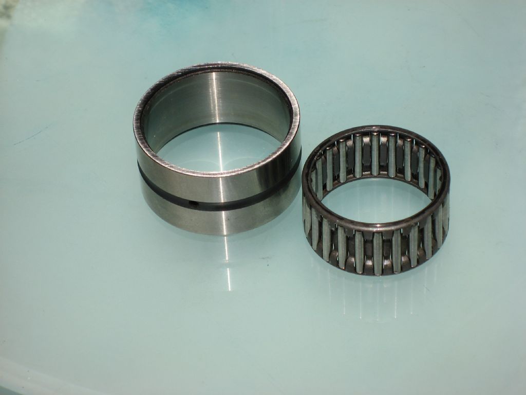
Hello Gray, Sorry for the tardy reply, but we took a few (sunny) days in Cardiff on family business, without the laptop. I must complement you on the excellence of your pictures. The super machining and the high quality photos are a joy to the eye. I attach a photo of the old roller assembly take from my FB2.
Ray |
 and No.455 (630°-660°


Magazine Locator
Want the latest issue of Model Engineer or Model Engineers' Workshop? Use our magazine locator links to find your nearest stockist!
Sign up to our Newsletter
Sign up to our newsletter and get a free digital issue.
You can unsubscribe at anytime. View our privacy policy at www.mortons.co.uk/privacy
Latest Forum Posts
- hemingway ball turner
04/07/2025 14:40:26 - *Oct 2023: FORUM MIGRATION TIMELINE*
05/10/2023 07:57:11 - Making ER11 collet chuck
05/10/2023 07:56:24 - What did you do today? 2023
05/10/2023 07:25:01 - Orrery
05/10/2023 06:00:41 - Wera hand-tools
05/10/2023 05:47:07 - New member
05/10/2023 04:40:11 - Problems with external pot on at1 vfd
05/10/2023 00:06:32 - Drain plug
04/10/2023 23:36:17 - digi phase converter for 10 machines.....
04/10/2023 23:13:48 - More Latest Posts...
- View All Topics
Support Our Partners


Shopping Partners
Subscription Offer

Latest "For Sale" Ads
- Reeves** - Rebuilt Royal Scot by Martin Evans
by John Broughton
£300.00 - BRITANNIA 5" GAUGE James Perrier
by Jon Seabright 1
£2,500.00 - Drill Grinder - for restoration
by Nigel Graham 2
£0.00 - WARCO WM18 MILLING MACHINE
by Alex Chudley
£1,200.00 - MYFORD SUPER 7 LATHE
by Alex Chudley
£2,000.00 - More "For Sale" Ads...
Latest "Wanted" Ads
- D1-3 backplate
by Michael Horley
Price Not Specified - fixed steady for a Colchester bantam mark1 800
by George Jervis
Price Not Specified - lbsc pansy
by JACK SIDEBOTHAM
Price Not Specified - Pratt Burnerd multifit chuck key.
by Tim Riome
Price Not Specified - BANDSAW BLADE WELDER
by HUGH
Price Not Specified - More "Wanted" Ads...
Get In Touch!
Do you want to contact the Model Engineer and Model Engineers' Workshop team?
You can contact us by phone, mail or email about the magazines including becoming a contributor, submitting reader's letters or making queries about articles. You can also get in touch about this website, advertising or other general issues.
Click THIS LINK for full contact details.
For subscription issues please see THIS LINK.
Digital Back Issues


Donate

 Register
 Log-in
Model Engineer Magazine
- Percival Marshall
- M.E. History
- LittleLEC
- M.E. Clock

ME Workshop
- An Adcock
- & Shipley
- Horizontal
- Mill

Subscribe Now
- Great savings
- Delivered to your door

Pre-order your copy!
- Delivered to your doorstep!
- Free UK delivery!