Member postings for Mark Smith 3
Here is a list of all the postings Mark Smith 3 has made in our forums. Click on a thread name to jump to the thread.
| Thread: Old lathe, chuck accuracy |
| 25/01/2010 04:43:52 |
Hi I am new to engineering and I have a very old lathe. My problem is the 3 jaw chuck has always been inaccurate, as anything I put in it wobbles visibly. I got sick of this and decided to check the runout (without a DTI) and it was about 1/32" out. I removed the chuck from its back plate and checked that and it was bad. I took a skim off it and got it running true and reassembled the chuck. Things are better but not perfect - if it is ever possible to get a perfect 3 jaw. My question is what else, besides a new lathe, can I do to improve matters? Shims? there are no marks that I can see that register the chuck with the back plate.
Mark |
| Thread: Hot air and stirling engines |
| 22/01/2010 19:13:57 |
That's impressive, Ian. Did you just use a counterweight on the crank? My ross yoke engine is about the same stage. The weather is foul today so I should get plenty done on it.
Mark |
| Thread: Stirling engines |
| 18/01/2010 04:41:07 |
In my experience, such as it is, besides leaks and friction, timing is another big factor. Some engines are happy at 90 degrees and others somewhat either side of that magic number. Also I have found that a minimal clearance of the displacer from the top of the hot cap is very critical. Are you able to alter the timing? Oh, I have just looked at the plans and I see it is a bell crank rocker driving the displacer, very difficult to alter as it is driven off the main crank. I tend to use offset cranks that are easily changed to advance or retard the timing. My latest engine the "Devon" was a difficult engine to get going but after a lot of adjustments to the cylinder position and the timing it went and now starts after a short warm up with one flick. On the Stirling II there appears to be some adjustment on the displacer tube as the big end screws into the tube. You could try adjusting that until the displacer just touches the top of the hot cap and back off to just clear. Hope this helps.
Mark Edited By Mark Smith 3 on 18/01/2010 05:20:36 |
| Thread: Drill Chuck, Dismantle |
| 17/01/2010 06:27:48 |
No,Ian much bigger about 18mm dia. anyway problem solved. |
| 17/01/2010 03:02:55 |
Thanks, Chris, I took the bull by the horns and went to the jacobs web site it said to chuck a large allen key in the chuck and whack it. Well it worked. The chuck unscrewed after several whacks. It dismantles easily with a slipring at the back of the chuck. I have stripped and oiled it; it works better now.
Mark |
| 16/01/2010 19:21:30 |
I have a Hawkins drill press you probably won't have heard of as it was made in Christchurch NZ many years ago. My problem is that the chuck needs servicing as it is stiff to operate and doesn't hold the drills securely. It also won't hold drills below 1/8'. I think it is a screw on chuck as there is no slot in the quill and a shaft runs through the pulleys with a long keyway. How do I get it out without breaking something. Once out I should be able to strip it after reading the previous posts.
Mark |
| Thread: Simpler the Better -what do you use? |
| 12/01/2010 06:14:11 |
Thanks Colin I have down loaded Solid edge. It does everything I need in the 2D Environment. Very intuitive and a clear tutorial. There is so much to learn about this program, it is a "learn as you go" after the tutorials which give you the basics. There is also a comprehensive help section and a hint bar at the bottom as you access each feature. I had tried A9CAD but nothing seemed to work as expected and there is no real help section.
Mark |
| Thread: Hot air and stirling engines |
| 11/01/2010 06:44:37 |
No, I haven't seen a Manson engine but I have heard of it. I'd be interested to hear how you get on with it and see some pics. By the by I don't claim to be an expert just a student of stirling engines and a tyro at model engineering. I too am searching for that ellusive missing power and efficiency that these engines promise without the huge expense and time Phillips has invested - probably pie in the sky but you never know unless you try.
Pressurisation, it is claimed to be the single best thing we can do to increase the power, but, as Ian has pointed out in a previous post, there is a limit to how much pressure a given engine can stand and that depends on the fluid used and how efficient the cooler and heaters are. So you are right to say that the greater the diffference in temperature excursion the more efficient and powerful the engine but it all depends on so many other factors; pressurisation is just one of them. However, having said that, Andy Ross has made a 35cc engine that produced 44 watts at 2,750 RPM at atmospheric pressure. That shows there is a lot to be learned before we get to adding any extra pressure - given that most model engines are measured in fractions of watts.
How are you holding up with all the snow. I hesitate to say the tempertatures here in Christchurch are usually in the mid twenties. I see the snow is causing problems right across europe at the moment. |
| 09/01/2010 18:37:05 |
Hi Ian,
the stroke is 30mm and the pin dia. is 5mm. I made it out of brass built up and brazed together as I don't have access to a mill at present. I thought it seemed smooth and even but it jammed at the extremites. Maybe too much flex in the displacer shaft which is 3/16".
Mark |
| 08/01/2010 18:58:53 |
Hi Gordon,
I can't quote actual figures for a given engine but in my reading I seem to notice that the hot end is around 700C and the cold end ideally should be 100C, but that depends on many factors including: heat source, hotcap material, length of cylinder, whether a regenerator is present and how efficient the cooling system is. Ian SC might be able to tell you more about specific engines and their operating temperatures.
Another very good book by Read and Hooper Stirling Engines has a weath of information and while there are sections that deal with thermodynamics and associated formulae, most of the book is highly readable. It may be out of print now but your library should be able to source it from a University or National library.
My pressurised engine is still giving me trouble as the crank is closer to the piston than is ideal and the crank angle driving the displacer is too great and causes side thrust on the shaft therefore friction. I tried a scotch yoke but that failed too. Now the plan is to fit a small bell crank in the bottom right side of the crankcase; this looks promising as the displacer shaft is only subject to small side forces. I hope to make this in the next day or two- but not today as the wife wants to go fishing!
 Mark |
| 04/01/2010 19:38:29 |
HI Gordon, I see your point as I made a displacer that was peppered wth holes at each end and filled with poly pads, yet the engine ran. I want to try it on my reliable old engine to see if that still holds good because that engine refused to run with a small crack at the hot end of its displacer. Sealed displacers raises the question about moving regenerators that are tolally unsealed. Most of the books I have read on this subject say that if the displacer is made from thin aluminium or very thin steel, a tiny hole may be drilled in the base to allow some pressure inside stopping the walls collapsing.
All very confusing but it shows there are things about these engines that are yet to be discovered. That's what is so good about this forum, we can all try things out and report our results - even if not very scientifically - to our fellow postees.
See if you can get an Artlcle by David Urwick ("Stirling Engines" More research and development). from ME18 Feb 1977 it makes for interesting reading on the subject of moving regenerators - in other words open displacers - and dead space volumes.
Just as an after thought, I wonder if all has something to do with total swept volumes. The magic numbers I've seen are 1:1.5 power cylinder to working cylinder ratio. Yet a rider has in most cases a 1:1 swept ratio. It would be interesting to see if a hole in the displacer-like extension to the hot piston made a difference.
Ian, can you post a link to that site you were looking regarding balancing yokes.
Mark
Edited By Mark Smith 3 on 04/01/2010 19:42:34 Edited By Mark Smith 3 on 04/01/2010 19:44:55 |
| 04/01/2010 04:58:07 |
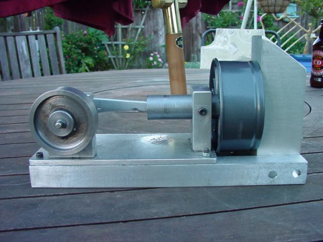
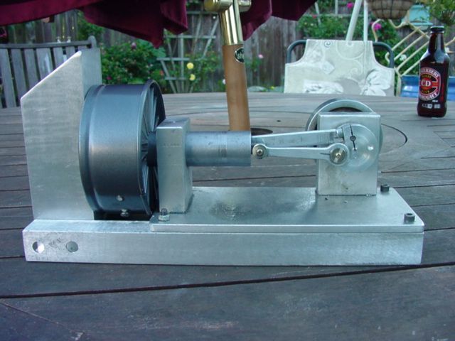
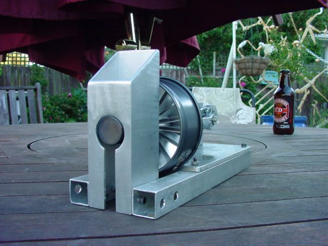
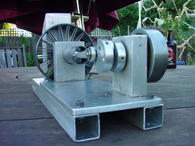
I have completed the Ross yoke mechanism today. It is tricky to get right but worthwhile. I now know why a balancing system is needed as, without the reciprocating pistons, just its own action causes a lot of vibration. I'm not sure how I will balance it at this stage maybe solve that when I get the rest of the engine finished. Andy Ross's solution was a counter rotating balance wheel driven from gears and mounted above the crankcase. I would like to do away with the gears somehow and mount it in line with the crankshaft.
The great thing about this drive is how variable it is from choice of the phase angle to unequal strokes if that's what your design calls for. One of James Rizzo's books (can't recall the title) volume II has an apendix that shows a way to vary the phase angle at will while the engine is running as a form of speed control.
Ian, did you get my text? your email address still won't work, There is something wrong with it. |
| 01/01/2010 18:43:10 |
Yes,Ian your email came through but when I sent you a reply it bounced back, very odd.
I do have some plastic rod as you suggest, might look at resurrecting that LTD when I have cleared my bench of other projects. Still have to sort out the pressurised engine yet but you have side tracked me with Andy Ross's artlicle and your little wooden model,so I have made the yoke to go in a new engine maybe for another nephew. I think it might be possible to drive a counter rotating balance from the rocking lever; it would be simple enough to try just need another bearing on the opposite side to the crank, and a shaft with the weight and drive pin.
This engine will be a Rider and I have most of the bits I need already, just have to buy a length of AL bar 20mmx50mm to house the two cylinders. Is your engine a Rider?
I got a Mitre 10 gift voucher for Christmas and bought a digital caliper; Magic! It reads imperial and metric, measures inside outside and depth. no more fiddling with micrometers.
Thinking of coming out to you for a visit if that's alright, but I will ring to confirm.
Mark Edited By Mark Smith 3 on 01/01/2010 18:44:46 |
| 30/12/2009 07:49:43 |
Ian can you send me an email as the last one I sent you got bounced back address wrong which I don't understand as I have sent you mail before.
I have an LTD that I started a couple of years ago but got sidetracked. The frame with the bearing and crank arangement are complete as are the two aluminium plates, machined and drilled. I found the clear plastic cylinder at the supershed, some sort of jug i think. I just need to make a suitable piston and a foam displacer to finish it. I will look into nylon screws as you say.
Mark |
| 30/12/2009 02:50:17 |
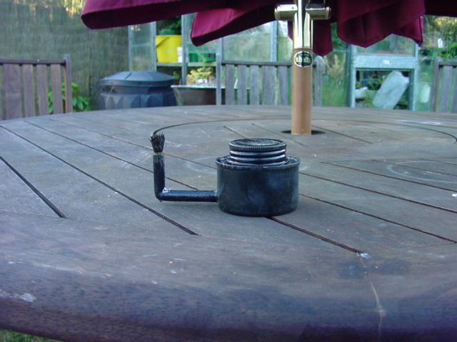
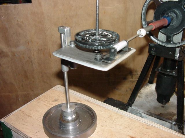
I might be wrong here but I assume by Delta we mean the configuration of the low temp deltaT engines.
I have made my rev counter today. It is made from bits I found around my shed, namely: sewing machine parts, 95 tooth gear and worm from a VHS recorder, and a base made from a flywheel I had turned but wasn't happy with.
My latest engine, The Devon runs at 820rpm while the engine you see was doing 980rpm. Next thing is a torque arm to measure the watts or part thereof.
By the by you said you found a bearing in part of a VHS recorder, well there are two more very nice bearings in the head rotor. Mark
Edited By Mark Smith 3 on 30/12/2009 02:55:07 Edited By Mark Smith 3 on 30/12/2009 02:56:58 |
| 29/12/2009 18:58:09 |
Ian, Is your high temp delta working? How hot do you get the hot side and what do you use for the cold side? |
| 26/12/2009 18:17:38 |
Sorry Pete,
The designs looked ok I didn't realiise they were junky and plastic. To save you some time have a dekko at Wheeltappers little engine on page 5. It would look very nice with brass parts.
Mark |
| 25/12/2009 19:47:00 |
Hi Pete try this site http://cgi.ebay.co.uk/ws/eBayISAPI.dll?ViewItem&item=160380845916 it has lots of brass, a beam, and spoked flywheel by the look of the pic.
Or try this one http://www.ministeam.com/acatalog/Bohm_Stirling_Engines_and_Kits.html it looks a bit scientific but has all the elements you want. Mark Edited By Mark Smith 3 on 25/12/2009 19:54:19 |
| Thread: Washers |
| 21/12/2009 05:44:18 |
Gordon, You poor bugger...2cv? I drive a VW kombi I must be as sick as you.
Mark |
| Thread: Hot air and stirling engines |
| 19/12/2009 18:48:36 |
Here are a couple of pics of The Devon, my grand nephews engine, nearly finished. I just need to make a base, fit a generator, and a safe box to house it. As you can see it is a Beta and features a cooling unit made from junk parts namely, a heat sink from a computer joined and bent round into a fan. The shroud is a baking ring for pavlova. I got the idea for the stack from one of Roy Darlington's marine engines. Specs are 25mm bore, 20mm stroke, displacer stroke 30mm. The cylinder is one piece held in the frame with a cap screw, this makes adjustments easy as well as simple to disassemble if required. All the rods and shafts have ball bearings from hard drives and features an aluminium piston with my usual leather cup seal and teflon stuffing box to seal the displacer shaft. It starts easily once warm and runs at a good speed ( can't measure that yet).
Maybe I can now get on with solving the problems with my big pressurised engine...unless another nephew or grandson..........
     |
Magazine Locator
Want the latest issue of Model Engineer or Model Engineers' Workshop? Use our magazine locator links to find your nearest stockist!
Sign up to our Newsletter
Sign up to our newsletter and get a free digital issue.
You can unsubscribe at anytime. View our privacy policy at www.mortons.co.uk/privacy
Latest Forum Posts
- *Oct 2023: FORUM MIGRATION TIMELINE*
05/10/2023 07:57:11 - Making ER11 collet chuck
05/10/2023 07:56:24 - What did you do today? 2023
05/10/2023 07:25:01 - Orrery
05/10/2023 06:00:41 - Wera hand-tools
05/10/2023 05:47:07 - New member
05/10/2023 04:40:11 - Problems with external pot on at1 vfd
05/10/2023 00:06:32 - Drain plug
04/10/2023 23:36:17 - digi phase converter for 10 machines.....
04/10/2023 23:13:48 - Winter Storage Of Locomotives
04/10/2023 21:02:11 - More Latest Posts...
- View All Topics
Support Our Partners


Shopping Partners
Subscription Offer

Latest "For Sale" Ads
- Reeves** - Rebuilt Royal Scot by Martin Evans
by John Broughton
£300.00 - BRITANNIA 5" GAUGE James Perrier
by Jon Seabright 1
£2,500.00 - Drill Grinder - for restoration
by Nigel Graham 2
£0.00 - WARCO WM18 MILLING MACHINE
by Alex Chudley
£1,200.00 - MYFORD SUPER 7 LATHE
by Alex Chudley
£2,000.00 - More "For Sale" Ads...
Latest "Wanted" Ads
- D1-3 backplate
by Michael Horley
Price Not Specified - fixed steady for a Colchester bantam mark1 800
by George Jervis
Price Not Specified - lbsc pansy
by JACK SIDEBOTHAM
Price Not Specified - Pratt Burnerd multifit chuck key.
by Tim Riome
Price Not Specified - BANDSAW BLADE WELDER
by HUGH
Price Not Specified - More "Wanted" Ads...
Get In Touch!
Do you want to contact the Model Engineer and Model Engineers' Workshop team?
You can contact us by phone, mail or email about the magazines including becoming a contributor, submitting reader's letters or making queries about articles. You can also get in touch about this website, advertising or other general issues.
Click THIS LINK for full contact details.
For subscription issues please see THIS LINK.
Digital Back Issues


Donate

 Register
 Log-in
Model Engineer Magazine
- Percival Marshall
- M.E. History
- LittleLEC
- M.E. Clock

ME Workshop
- An Adcock
- & Shipley
- Horizontal
- Mill

Subscribe Now
- Great savings
- Delivered to your door

Pre-order your copy!
- Delivered to your doorstep!
- Free UK delivery!