Member postings for Clive Farrar
Here is a list of all the postings Clive Farrar has made in our forums. Click on a thread name to jump to the thread.
| Thread: Which Cutter Grinder? |
| 03/01/2011 20:00:30 |
I have made the more sophisticated one from WSP 35.
It was a good beginers project and can deliver some very good results.
I also made the mounting board with angle iron and ipcked up a 125w bench grinder from B&Q for a tenner. Diamond cup wheel fron RDG.
Grinder sheft was trued up as Harold states at the end of the book. An accurate spacer was then made to fit the cup wheel.
I have mainly done lathe tools. I rough grind, off hand on the othe 6" grinder to get them some where near. Then I set up the grinding jig with the alloy angle gauges and polish the cutting edges up with the diamond wheel using the vernier feeds. I make the simple square bolck holders for doing a few milling cutters. I only intend ever doing the tips so i do not need the rotary collets jig he also lists drawings for.
The diamond wheel can not take lots of material off so you either need to use a grit wheel at the other end or a separate one like I do.
It is a bit of a faff swapping the angle iron around the base board.
Final point in the last MEW Harold states that he has made new 3mm side arms for his insead of the original 8mm. A good move if you ask me and I will be changing mine in due course. I have skinned my knuckles a couple of times getting the thick ones tight enough.
Regards Clive |
| Thread: Pprojecting a circle onto a boiler barrel |
| 10/12/2010 15:08:02 |
John and All as stated I realised my original drawing was not the full story.
And yes it does look like a tangent application but it was the only way i could get the template profile that would need to laid over , curved round the boiler to scibe a line that when cut would be the circular hole required.
Rather than fiddle about and misslead some more i had a quick look on the web and came up witht he following link.
about half way through it does the intersection of two cyinders. That is what i was trying to convey but failed to do so correctly. I was close though
 Regards Clive |
| 09/12/2010 21:19:32 |
Hi Vincent,
its been bugging me all day that my diagram may NOT correct. As its 30 odd years since i last did this sort of thing I have missed a bit out.
So I think if you use this method you need to test it out on something unimportant like a toilet role core.
So what have i done wrong? the red dot blue dot on the circle is the boiler diameter but when you develop that out into the flat it becomes half the circumference i.e 3.142 times longer.
Some how there needs to be an intersect line intersposed between the boiler circle and boiler development such that as you transfer the lines across they correct the positioning by a factor of Pi but at the moment I can not remember how.
Not sure if I have made that better or worse but it gives you a starting point for a net search.
If you give me diameters and aproximate location I will try and get some time to do it properly but with work at the moment i can not promise.
Regards Clive |
| 08/12/2010 15:15:15 |
There are two ways of doing it. on the centre line of the boiler where you want the flange to go mark the true OD of the flange on the line. Then using a circular object or hole and a very stong light project a shaddow onto the line on the boiler, at 90 degrees to the line on the boiler. Adjust the distance of the object untill its shaddow touches both of your marked points on the centre line. Then draw in the rest of the shaddow out line and that is the development of you pipe projected onto the boiler. If you want a paper template to follow have a look at the attached diagram. It should be easy to see how the pipe has been divided up into sections and then those lines are projected in two directions to get points of intersection on the boiler, the brown dots in the diargam. Link the dots and that is your outline. The diagram is basic so you dont get a good set of points to join up. Easily solved just add more lines and intersections to fill in the blank bits. I hope that helps regards Clive 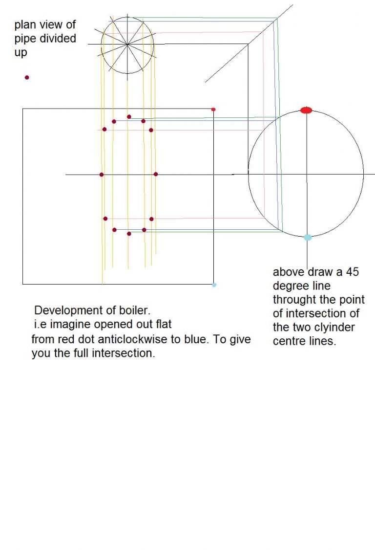 |
| Thread: Band saw conversion |
| 04/12/2010 09:04:05 |
Hi Robert,
I have had a look at our works machine and I see what you mean about the small pulley. I was surprised to find that the drive pulley is just a single flat flange.
Using wonderfull excel the standard speeds check out and so with the standard drive pully the lowest speed I think you can get on this machine is 267 m / minute and that would be by building up the band drive flange to 320 mm OD , i.e. the same is the tyred band drive wheel. There is probably not that much adjustment on the motor mount.
To get to the speed you want from the standard motor pulley would need a 2 m diamater on the band drive flange. err NO!
So if you turn that on its head you could look to make a smaller tyred drive wheel but to get down to 83 m /min would need the drive flange at 320mm and the tyre drive band at 100 mm dia, which is too small the blade would fatigue too quickly.
So I would say you either have to reduce the motor speed or accept that you can not cut metal at your desired speed on this machine and take one of the alternative routes suggested.
regards Clive |
| 04/12/2010 09:01:40 |
Hi Robert,
I have had a look at our works machine and I see what you mean about the small pulley. I was surprised to find that the drive pulley is just a single flat flange.
Using wonderfull excel the standard speeds check out and so with the standard drive pully the lowest speed I think you can get on this machine is 267 m / minute and that would be by building up the band drive flange to 320 mm OD , i.e. the same is the tyred band drive wheel. There is probably not that much adjustment on the motor mount.
To get to the speed you want from the standard motor pulley would need a 2 m diamater on the band drive flange. err NO!
So if you turn that on its head you could look to make a smaller tyred drive wheel but to get down to 83 m /min would need the drive flange at 320mm and the tyre drive band at 100 mm dia, which is too small the blade would fatigue too quickly.
So I would say you either have to reduce the motor speed or accept that you can not cut metal at your desired speed on this machine and take one of the alternative routes suggested.
regards Clive |
| 04/12/2010 09:00:52 |
Hi Robert,
I have had a look at our works machine and I see what you mean about the small pulley. I was surprised to find that the drive pulley is just a single flat flange.
Using wonderfull excel the standard speeds check out and so with the standard drive pully the lowest speed I think you can get on this machine is 267 m / minute and that would be by building up the band drive flange to 320 mm OD , i.e. the same is the tyred band drive wheel. There is probably not that much adjustment on the motor mount.
To get to the speed you want from the standard motor pulley would need a 2 m diamater on the band drive flange. err NO!
So if you turn that on its head you could look to make a smaller tyred drive wheel but to get down to 83 m /min would need the drive flange at 320mm and the tyre drive band at 100 mm dia, which is too small the blade would fatigue too quickly.
So I would say you either have to reduce the motor speed or accept that you can not cut metal at your desired speed on this machine and take one of the alternative routes suggested.
regards Clive |
| 01/12/2010 12:28:28 |
you say you can not speed control it but I would have thought you could use a dimmer switch to provide a variable voltage.
I guess the big problem would be that it would drop the torque to much and make cutting a very slow process.
Nowt to stop you trying it though.
regards Clive |
| 01/12/2010 12:24:44 |
See what you mean there is not much depth to one of these,we have one at work.
As i see it the only way to get down to the speed you want is to sort out pully changes.
I have an old Burgess one that has a roundthane drive belt 6mm dia and a pair of three step pulleys that give me metal wood and sanding speeds. they are about 40 mm thick and probalby 120 mm od max.
Do you think you could replace yours with something similar? I can take a photo if you want.
Regards Clive |
| Thread: Disassembling of Minimill / X2-clone / XJ-12 Ballbearings |
| 07/08/2010 20:50:38 |
Ian I can not say for sure as the only rev counter i have is for model aircraft and works in steps of 100.
It flickers on 1 but the tippex marks are going round too quick to count so I think it is fairly close to 100. It does not take much of an increase on the speed pot for it to steady at 1.
I have not tried cutting anything at that speed but I suspect it will only do very fine cuts when going that slow.
Mind you the pullys were easy enough to turn up so a slightly bigger one, 90 mm ?, would probably get you down to the speed you need.
Regards Clive |
| 06/08/2010 22:57:27 |
Well chaps my belt drive conversion is now finished.
To suit my machine I had to make several small dimensional modifications to the drawings I was working from. Mainly because my motor is totally different to that drawn.
Once I had sorted out the excessive bearing pre load that meant top speed was about 60 rpm it is running great.
It is much quieter than the gear drive.
Hi low top speeds have gone from 1100 to 1700 , 2500 to 3200 a good range and a good increase. Although for me I susspect it will rarely be out of low gear.
Very very pleased with the result and I would recommend the job to anyone who smashes their gears.
regards Clive |
| 21/06/2010 21:54:19 |
Mine is a WARCO mini mill and the switch box gets in the way of both mode I have seen and leaves no space to dog leg round the back of it.
After a bit of measuring and ponderingI worked out that I could move it down so the top was level with the head thus giving me space fot the T shaped mounting plate.
The draw back is that it is now below the bottom of the head. The just acceptable news is that that bottom edge is level with the morse taper mouse.
that should not be a problem for me as I nearly allways use an ER32 collet chuck which drops the cutter some 50 mm + below that point.
Now to start on the metal.
Regards Clive |
| Thread: BallBearings and gears on miniMill XJ9512(aka xj12 / fervi-t058 /...) |
| 13/06/2010 21:09:57 |
please see the dissassembling the x2 mill thread for the bearings I have used.
They are open and were only £6 each
regards Clive |
| Thread: Disassembling of Minimill / X2-clone / XJ-12 Ballbearings |
| 13/06/2010 21:06:23 |
Well chaps I have just started to convert mine to belt drive.
I have the drawings and info from John Rudd I will need some carefull thought to mod these to suit my WARCO due to the spped controller box location.
I have stripped it all down today and after extracting the small gear that had broken into about 20 bits and removed 4 teath from the other gear.
The first job was to replace the bearings with taper rollers.
My bottom ball bearing also fell apart when removing the shaft from the head. The inner race was a VERY tight fit on the shaft. If I did not have a No3 broach press I would not have got it apart.
They have been replaced with Nachi H-E30206J bearings from ARC Eurotrade. These are exactly the same as those used in the mini lathe, as mentioned above.
I also needed the press to get them back on. Fitting these has reduced the length of shaft above the bearing by approx 4 mm.
As I have no intention of using gears ever again I have removed the layshaft from the head.
I have left the small bearing in the head and blanked the centres with grommets.
I know the tapers are open at the bottom but so are the ball bearings and the metal fling washer and plastic collar over the bearing obviously do their job as there was NO contamination in the old ball race.
If only the rest of the mod would go as easily.
Regards Clive |
| Thread: glow plugs & fuel |
| 01/06/2010 20:24:59 |
I suggest you go to a model aircraft shop and get some model technics Forula Irvine with 5 % nitro.
I run all ( 8 ) of my FS engines on it. There is a big range of 2 stoke plugs with diferent heat ranges, but not so for four strokes.
The best in my oppinion are OS "F" plugs at abut £4.50 each.
A good second best is Just engines own brand.
Look up just engines on the web and you will find lots of good info.
regards Clive
PS were did you get you plans from are there any links you can send me. |
| Thread: Convert cheap digital calliper to height gauge? |
| 08/03/2010 19:52:29 |
Sorry for posting twice it seemd to dissapear the first time
clive |
| 08/03/2010 19:51:35 |
if you follow the MEW article please be aware that the base drawing is incorrect.
It shows the threaded hole being bisected by the mounting face.
If yo look at the little picture just up and right you will see the correct position.
i.e. CL 10.50 mm up from the face without the step.
I got a second vernier from Aldi for £8 so i can now have one mounted or in a fixed measure leaving the other free for general use.
Regards Clive |
| 08/03/2010 19:47:18 |
If you use the MEW drawings make sure you READ them thoroughly first.
The base section is incorrect as drawn. It shows the clamp thread hole going through the mounting step. Look at the photo up and right in the article and you will see where it should be. The CL is 10.50 mm from the face oposite the step.
David has been e mailed but these things take time to be published.
But it does work as I have made one from scrap bits. I am pleased with it for the amount of use it will get it is a good infill job and has saved me from "collecting" another expensive instrument just in case I might need it.
I also got a 2nd vernier from Aldi so that I can have a settign on one and the other for free measurements.
Regards Clive |
| Thread: Warco Mini Mill Drive Belt |
| 14/02/2010 20:24:34 |
JW than ks for that I was having a preliminary look last night and realised i would have to move the control box.
Not sure where to though yet as dropping it down will loose clearance.
I may look at repositioning the fixed pivot point for the motor so tha t it goes in the spare space between the back of the controler and the column.
Regards Clive
|
| Thread: Belt drive for mini mill / x2 sieg arc |
| 13/02/2010 19:29:14 |
We chaps I finally got through to M machine , who advertise on here, and picked up most of what I needed on Friday for a very reasonable price. They have loads of stuff and were very helpfull indeed, and the remaining bit is on order and should be in soon
I would reccomend them to anyone. I now need to cross check the drawing I got from John Rudd and start on my conversion.
I persisted in trying to find the Ali stock because i had heard of the problems with size missmatch from the US machines.
I am so glad i resisted the USA option. A large part of that choice was the potential duty and VAT that would be due on top of the purchase price and shipping charges.
I shall let you know how I get on.
Regards Clive |
Magazine Locator
Want the latest issue of Model Engineer or Model Engineers' Workshop? Use our magazine locator links to find your nearest stockist!
Sign up to our Newsletter
Sign up to our newsletter and get a free digital issue.
You can unsubscribe at anytime. View our privacy policy at www.mortons.co.uk/privacy
Latest Forum Posts
- *Oct 2023: FORUM MIGRATION TIMELINE*
05/10/2023 07:57:11 - Making ER11 collet chuck
05/10/2023 07:56:24 - What did you do today? 2023
05/10/2023 07:25:01 - Orrery
05/10/2023 06:00:41 - Wera hand-tools
05/10/2023 05:47:07 - New member
05/10/2023 04:40:11 - Problems with external pot on at1 vfd
05/10/2023 00:06:32 - Drain plug
04/10/2023 23:36:17 - digi phase converter for 10 machines.....
04/10/2023 23:13:48 - Winter Storage Of Locomotives
04/10/2023 21:02:11 - More Latest Posts...
- View All Topics
Support Our Partners


Shopping Partners
Subscription Offer

Latest "For Sale" Ads
- Reeves** - Rebuilt Royal Scot by Martin Evans
by John Broughton
£300.00 - BRITANNIA 5" GAUGE James Perrier
by Jon Seabright 1
£2,500.00 - Drill Grinder - for restoration
by Nigel Graham 2
£0.00 - WARCO WM18 MILLING MACHINE
by Alex Chudley
£1,200.00 - MYFORD SUPER 7 LATHE
by Alex Chudley
£2,000.00 - More "For Sale" Ads...
Latest "Wanted" Ads
- D1-3 backplate
by Michael Horley
Price Not Specified - fixed steady for a Colchester bantam mark1 800
by George Jervis
Price Not Specified - lbsc pansy
by JACK SIDEBOTHAM
Price Not Specified - Pratt Burnerd multifit chuck key.
by Tim Riome
Price Not Specified - BANDSAW BLADE WELDER
by HUGH
Price Not Specified - More "Wanted" Ads...
Get In Touch!
Do you want to contact the Model Engineer and Model Engineers' Workshop team?
You can contact us by phone, mail or email about the magazines including becoming a contributor, submitting reader's letters or making queries about articles. You can also get in touch about this website, advertising or other general issues.
Click THIS LINK for full contact details.
For subscription issues please see THIS LINK.
Digital Back Issues


Donate

 Register
 Log-in
Model Engineer Magazine
- Percival Marshall
- M.E. History
- LittleLEC
- M.E. Clock

ME Workshop
- An Adcock
- & Shipley
- Horizontal
- Mill

Subscribe Now
- Great savings
- Delivered to your door

Pre-order your copy!
- Delivered to your doorstep!
- Free UK delivery!