Member postings for Dr_GMJN
Here is a list of all the postings Dr_GMJN has made in our forums. Click on a thread name to jump to the thread.
| Thread: Clocking on a 4 Jaw indepdent |
| 21/10/2022 18:04:22 |
Posted by Hopper on 21/10/2022 04:41:27:
If you methodically use the following method, you can get it within a thou or so every time within one revolution of the chuck after the initial revolution to take the starting reading, so about a minute or two total. Chuck up your round bar as best you can by eye, using the concentric grooves on the chuck face as reference. (Or use the toolbit or toolpost almost against the job as a reference if preferred.) Set a dial indicator horizontally to bear on the job. Spin the chuck by hand until the needle is at the lowest point and set the bezel to 0 there. Spin chuck to the highest needle reading and note the reading. Spin the chuck until the needle reads half this amount and then reset the 0 to the needle. Now you can go around with your pair of small chuck keys, or "twiddlers" and set each jaw pair so the dial needle reads 0. Usually one go-around is enough to be within a thou or so. A second go around all four jaws will get it well within a thou if desired.
Once you try this and see how simple and effective it is, you will never go back to any other method. It literally takes one or two minutes to get the job running within a thou. I had done it by the usual slow old "trial and error" method with a dial indicator all my life until I read this method in a one-page MEW article by a Scandinavian chap whose name eludes me. It was a revelation in its simplicity and effectiveness. I can't recommend it enough. Note: You can often get that last thou of adjustment by tightening the jaw on the "high" side without bothering to loosen the opposing jaw first. Seems to be able to move the job a thou or so most times. This is the exact method I use. I’m no machinist, but can often get things centred to within half a thou in one go, mostly two though. With two chuck keys, it’s a doddle, and with my NOGA dti stand with fine adjustment *at the base*, I actually find the process quite therapeutic (the base mounted fine adjuster makes zeroing the dti laughably easy because you don’t actually touch it or the arm, therefore there’s no spring back). |
| 21/10/2022 18:04:18 |
Posted by Hopper on 21/10/2022 04:41:27:
If you methodically use the following method, you can get it within a thou or so every time within one revolution of the chuck after the initial revolution to take the starting reading, so about a minute or two total. Chuck up your round bar as best you can by eye, using the concentric grooves on the chuck face as reference. (Or use the toolbit or toolpost almost against the job as a reference if preferred.) Set a dial indicator horizontally to bear on the job. Spin the chuck by hand until the needle is at the lowest point and set the bezel to 0 there. Spin chuck to the highest needle reading and note the reading. Spin the chuck until the needle reads half this amount and then reset the 0 to the needle. Now you can go around with your pair of small chuck keys, or "twiddlers" and set each jaw pair so the dial needle reads 0. Usually one go-around is enough to be within a thou or so. A second go around all four jaws will get it well within a thou if desired.
Once you try this and see how simple and effective it is, you will never go back to any other method. It literally takes one or two minutes to get the job running within a thou. I had done it by the usual slow old "trial and error" method with a dial indicator all my life until I read this method in a one-page MEW article by a Scandinavian chap whose name eludes me. It was a revelation in its simplicity and effectiveness. I can't recommend it enough. Note: You can often get that last thou of adjustment by tightening the jaw on the "high" side without bothering to loosen the opposing jaw first. Seems to be able to move the job a thou or so most times. This is the exact method I use. I’m no machinist, but can often get things centred to within half a thou in one go, mostly two though. With two chuck keys, it’s a doddle, and with my NOGA dti stand with fine adjustment *at the base*, I actually find the process quite therapeutic (the base mounted fine adjuster makes zeroing the dti laughably easy because you don’t actually touch it or the arm, therefore there’s no spring back). |
| Thread: Stuart Twin Victoria (Princess Royal) Mill Engine |
| 18/10/2022 23:23:43 |
Ramon - the idea was/is to build the Proncess Royal version of the Twin Victoria, pretty much to the plans from the magazine. For a second model and with my limited experience I think it's about the right amount of scale detail; it was never going to be some kind of perfect replica. I'm all for trying to make a few minor embellishments like glass oilers etc, but I'm also fine with it being 'semi-scale', such as with the main bearings we discussed previously. I suppose that attitude might seem strange, but I think I'll be happy with it once it's complete. The parquet thing was just a whim, and since I've not seen it before on an engine model I thought I'd have a go. If it looks a bit naff I'll bin it and try something else - probably plain wood. BTW the very first thing I noticed at the Midlands show last Saturday was the Twin Victoria on the Stuart Moldels stand opposite the main entrance. I was surprised to see it fitted to two separate free-standing base blocks (at least I couldn't see that they were connected by anything other than the crankshaft). |
| 18/10/2022 15:40:54 |
Thanks guys - I'll figure something out and see what it looks like. Roy - OK, the museum isn't a working environment, but the image Jason just posted appears to be? End of the day it's not a scale model of a specific engine, so if steam engines can be mounted on wood - or at least within a wooden floor environment - then why not do something a bit different? |
| 18/10/2022 13:35:52 |
Posted by JasonB on 18/10/2022 13:16:06:
Ah but did the museum just put it on planks? It's original working enviroment may have been different
Probably, but it's a fairly large working steam engine, bolted to a wood covered floor. Good enough for me! I was thinking of pasting brick paper around the inside of the wheel well to give a bit more interest too. I'll mess about with some CAD of different options, and might even try a small section of parquet flooring to see how it looks with the various features like Ramon's concrete MDF bases etc. I suppose I could get some 1" ply and make a temporary base for setting up. After all everything will need setting up again after painting. I can't finalise & paint the beds yet until I've figured out what holes will be needed for whatever cylinder drain pipework there will be.
|
| 18/10/2022 13:08:55 |
Thanks guys. Yes, it's just a wooden base that's got a bit more interest to it that I want. Nothing lost but some time if it looks rubbish; I'd just use a plain wooden one. Here's one you must have missed Roy! Object of the week - Mill Engine - Leeds Museums & Galleries |
| Thread: Stuart 10V rebuild |
| 17/10/2022 22:05:21 |
I also made the valve chest a bit wider than the valve face on mine do that the cladding fitted flush all the way around. |
| Thread: Stuart Twin Victoria (Princess Royal) Mill Engine |
| 17/10/2022 21:27:24 |
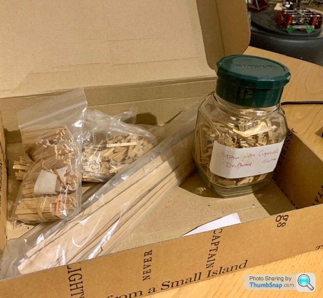
Thanks Ramon. I wasn’t aware you could activate PVA like that. It might be good to get the whole lot layer out properly, then iron it. I know some PVAs are re-dilutable with water (Formula 560 Canopy Glue for example), whereas the outdoor stuff is obviously permanent. I always use the former for models because it gives you chance to correct things. I assumed the beds wouldn’t be placed on wood, I suppose it’s a bit of modeller’s license. I guess you could say the pieces might have butted up to the bed frames? I was going to use plain wood, but then when I inherited these chips I thought it would be good to use them, otherwise they will be scrap. I’d like to make a metal jig that holds at least 10 strips at a time. Shouldn’t be too difficult. I’m also pondering whether to make the cylinder jackets out of wood, like your marine engine. I don’t really know how to fix them though. The brass band method can to my eyes look a bit “added on later”, especially the band fasteners when they screw into the cylinder casting. Anyhow first I need to finish the bearings, the with the shaft done I can at least say the two halves can be linked, and that will be a decent step forward. Cheers.
|
| 17/10/2022 08:50:09 |
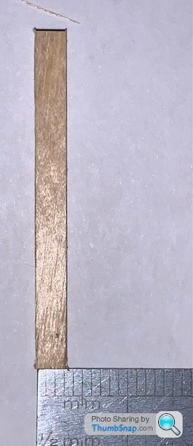
Thanks Jason. From what I found online, top rails should be a minimum of 950mm above the floor, with 1000mm being common. Of course these are modern standards. Maybe there were none back when engines like this were used, and perhaps people were shorter? Whichever scale it is, it’s only a matter of about 0.5mm difference, and since I’ve got a shed load of 4mm strips I might as well use them. I’ll have to make some kind of length trimming jig for multiple strips, and get a very sharp saw… |
| 16/10/2022 22:43:39 |
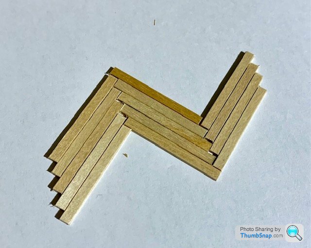
All, I think this might have been touched upon a while back, but I can't find where: I'm wanting to start the base for the model, and to do a parquet wood effect. I need to know the approximate scale of the model to get the floor looking right. |
| Thread: Engineering Shows |
| 14/10/2022 19:50:39 |
By the way are the PEC edge finders available in metric? I’m used to a 6mm diameter cylinder. |
| 14/10/2022 19:45:20 |
Thanks all - mixed reviews, but I’m sure I’ll enjoy it. |
| 14/10/2022 07:26:20 |
Yes you have to wary of assuming everything is cheaper at a show. I was gutted to miss out on a punch and die set ‘on offer’ from the manufacturer at the Telford plastic model show a few years back (they only had one left and when I decided to go back and get it, it was gone). When I checked online the exact same thing - again from the manufacturer- was around £10 cheaper even with postage. Is the model engineering hobby in decline - hence fewer display models? No idea, but people were saying that 16 years ago when I got my ML7, yet they seem just as expensive now for the same thing. I doubt many people scrap ML7s, so supply would be pretty constant. Everything seems to get worse the older people get: My Dad always said attending a Grand Prix at Silverstone was best in the ‘50’s & ‘60’s, yet I only knew it as an ‘enthusiast’ from the ‘80’s & 90’s, and thought it was awesome. These days I wouldn’t go if they paid me. Ill no doubt enjoy the show, and I’ll hopefully pick up an edge finder (I’ll check online prices first though) and some hexagon stock and some BA fasteners; the last lot I got were a nightmare to get delivered. I did buy my 10V kit from Stuart’s at Doncaster, and IIRC they did give a bit of show discount (can’t remember 100% about that though), and of course no postage to pay which made it a worthwhile purchase, plus it’s somehow nice to attend a show and come home with something. Thanks all. |
| 13/10/2022 13:44:19 |
All, I'm planning on going to the Midlands show on Saturday. I've only ever been to two engineering shows (Doncaster 2017 & 2018 IIRC) before lockdown. This was before I'd started my 10V, so I'll be looking at things with a slightly different eye now that I have an idea of what's what. I was wondering if there are any things that you can get at these events that are cheaper than online, or are you better just buying stuff like inserts from say Cutwel and be done with it? Reason I ask is that often you can find things that seem like bargains at events like this, but they turn out to be tat. So are there any suppliers that regularly attend shows that usually do good deals on inserts or tooling? I'd also like to get an electronic edge finder, but have no idea what to look for or what's a good price for what you're getting. Thanks! |
| Thread: Myford ML7 drip oilers |
| 16/09/2022 13:59:37 |
Thanks all. |
| 14/09/2022 07:37:38 |
All, one of my original Myford drip oilers has never worked properly - despite stripping and cleaning, it’s either full flow or nothing for some reason. The spring often binds on the pin or bore, giving the feeling of gouging metal when turning the knob. I’ve fiddled about with it to no avail. Years ago I bought a new pair, but they were pretty cheap and nasty and didn’t work well at all. Where can I get some original Myford oilers? EBay? Thanks.
|
| Thread: Stuart Twin Victoria (Princess Royal) Mill Engine |
| 09/09/2022 20:16:58 |
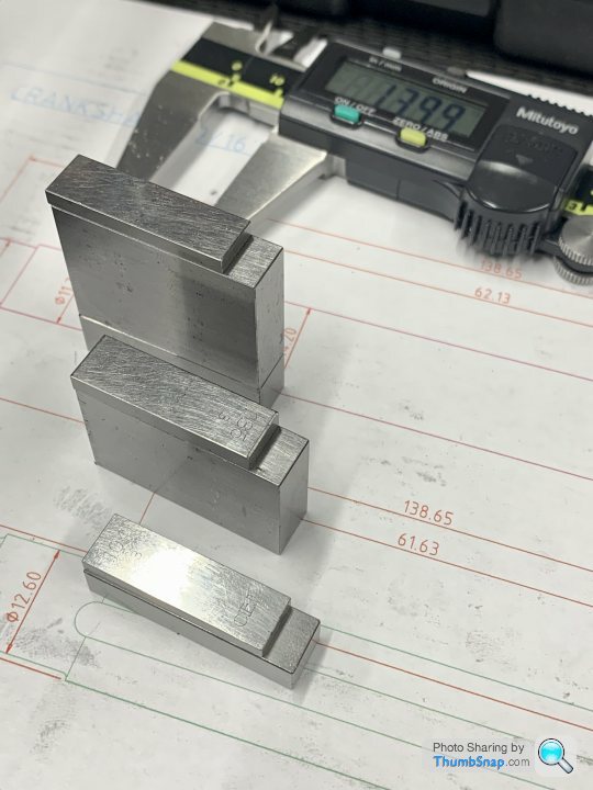
Did some length measurements: (I think I may have twitched when doing an undercut, hence the odd high readings).
|
| 09/09/2022 09:03:19 |
Ramon, if you read the summary, I mentioned I’d turned the three diameters on one end to the drawing, within the limit of my calipers, so it’s not like I’m totally inept. Using ‘my’ method just ensured the opposite ends were identical. Plus I’ve proved it works with no issue. What’s not to like apart from that some machinists wouldn’t do it that way in industry? |
| 08/09/2022 23:12:13 |
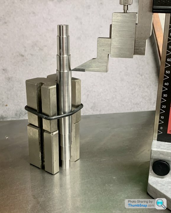
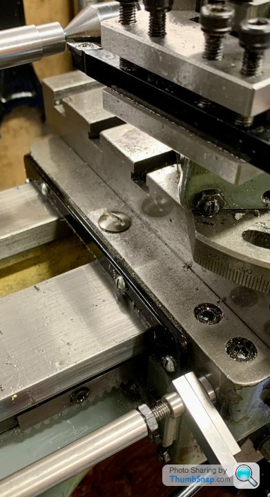
So this evening I machined the shaft using ‘my’ method. I was careful to evaluate after the first pair of diameters. I made up the three slip gauge stacks ready for the three length setups:
Removing the workpiece and swapping the carrier and re-fitting took less than 60 seconds, so it’s really a non-issue. DIAMETERS:
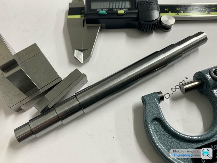
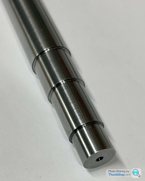
There is no way I could have got that consistency by turning individual ends. Clearly I’m relatively inexperienced and not saying for a second that others couldn’t do it, but for me, this method seemed completely legit, and the micrometer doesn’t lie. As an aside I asked one of our machinists at work about it (time served, very experienced) and he said he’d turn that particular shaft using exactly the same method; there was no reason he could think of why, if the centre setup was correct, it could ever yield different diameters (assuming no significant tool wear). I had to make at least one error, and so it proved. The middle continuous turned centre piece was supposed to be 14mm diameter, but ended up 13.9mm due to me forgetting to halve the difference to apply to the tool. Thankfully I caught it at 13.95mm due to incrementing down (I took the 0.05mm off to make final cut a fine one).
Lengths seem OK to within a few thou, but are difficult to measure. I’ll set up in the mill at some point and use the edge finder to bet a better idea of how accurate and consistent they are. Also added 0.005” undercuts, just because they seemed to look OK, and would remove any doubt as to binding in assembly. So whatever the wrongs or rights of the method, I’ve finally got the beginnings of a crankshaft! Edited By Dr_GMJN on 08/09/2022 23:19:18 |
| 08/09/2022 16:58:08 |
Jason, fair enough I’ll give it a go on the two roughing cuts for the crank webs and see what happens. If they’re identical to the limit of my micrometer I’ll crack on. If not I’ll measure and cut each end at a time. |
Magazine Locator
Want the latest issue of Model Engineer or Model Engineers' Workshop? Use our magazine locator links to find your nearest stockist!
Sign up to our Newsletter
Sign up to our newsletter and get a free digital issue.
You can unsubscribe at anytime. View our privacy policy at www.mortons.co.uk/privacy
Latest Forum Posts
- *Oct 2023: FORUM MIGRATION TIMELINE*
05/10/2023 07:57:11 - Making ER11 collet chuck
05/10/2023 07:56:24 - What did you do today? 2023
05/10/2023 07:25:01 - Orrery
05/10/2023 06:00:41 - Wera hand-tools
05/10/2023 05:47:07 - New member
05/10/2023 04:40:11 - Problems with external pot on at1 vfd
05/10/2023 00:06:32 - Drain plug
04/10/2023 23:36:17 - digi phase converter for 10 machines.....
04/10/2023 23:13:48 - Winter Storage Of Locomotives
04/10/2023 21:02:11 - More Latest Posts...
- View All Topics
Support Our Partners


Shopping Partners
Subscription Offer

Latest "For Sale" Ads
- Reeves** - Rebuilt Royal Scot by Martin Evans
by John Broughton
£300.00 - BRITANNIA 5" GAUGE James Perrier
by Jon Seabright 1
£2,500.00 - Drill Grinder - for restoration
by Nigel Graham 2
£0.00 - WARCO WM18 MILLING MACHINE
by Alex Chudley
£1,200.00 - MYFORD SUPER 7 LATHE
by Alex Chudley
£2,000.00 - More "For Sale" Ads...
Latest "Wanted" Ads
- D1-3 backplate
by Michael Horley
Price Not Specified - fixed steady for a Colchester bantam mark1 800
by George Jervis
Price Not Specified - lbsc pansy
by JACK SIDEBOTHAM
Price Not Specified - Pratt Burnerd multifit chuck key.
by Tim Riome
Price Not Specified - BANDSAW BLADE WELDER
by HUGH
Price Not Specified - More "Wanted" Ads...
Get In Touch!
Do you want to contact the Model Engineer and Model Engineers' Workshop team?
You can contact us by phone, mail or email about the magazines including becoming a contributor, submitting reader's letters or making queries about articles. You can also get in touch about this website, advertising or other general issues.
Click THIS LINK for full contact details.
For subscription issues please see THIS LINK.
Digital Back Issues


Donate

 Register
 Log-in
Model Engineer Magazine
- Percival Marshall
- M.E. History
- LittleLEC
- M.E. Clock

ME Workshop
- An Adcock
- & Shipley
- Horizontal
- Mill

Subscribe Now
- Great savings
- Delivered to your door

Pre-order your copy!
- Delivered to your doorstep!
- Free UK delivery!