Member postings for Dr_GMJN
Here is a list of all the postings Dr_GMJN has made in our forums. Click on a thread name to jump to the thread.
| Thread: Stuart Twin Victoria (Princess Royal) Mill Engine |
| 10/03/2023 22:34:08 |
Posted by Hopper on 10/03/2023 21:26:59:
Posted by Dr_GMJN on 10/03/2023 19:44:17:
The running fits seem fine, but I can't help thinking the surface finish could be better on the journals and shaft - it's pretty smooth in rotation, but if it's moved axially...I can tell it's been turned. Anyway, I think it's OK overall. If you want smoother on future jobs, try reaming the holes in the bearings for a smoother finish and use emery cloth to get the final smooth finish on the shaft. This gives you very fine control over the final shaft size for clearance too. Thanks Hopper. I don't have a 1/2" reamer, so the advice was to bore them instead. That worked OK. I did use wet and dry with some metal polish on the shaft bearings when I made the shaft. To be fair they're probably absolutely fine. It would just be nice to look at them and see a mirror finish is I guess where I'm at. |
| 10/03/2023 19:44:17 |
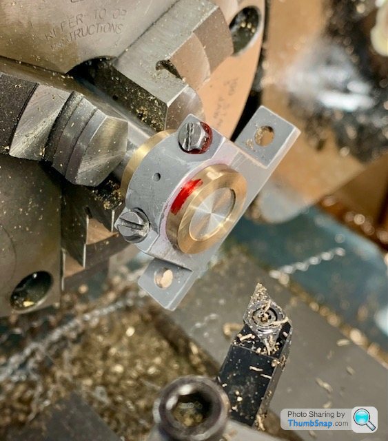
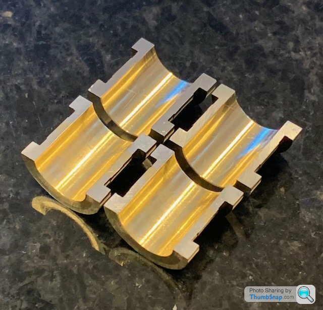
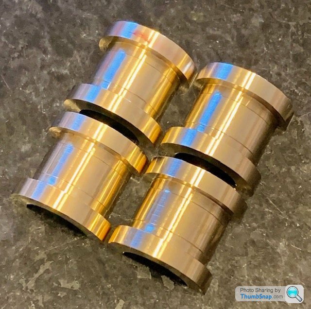
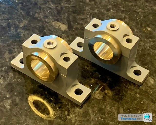
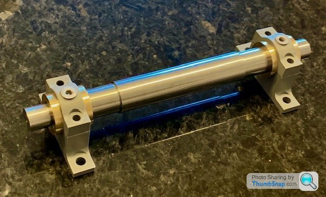
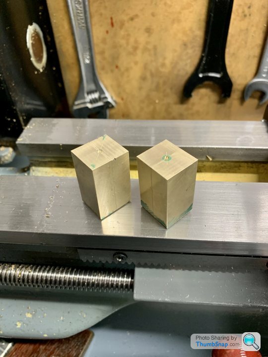
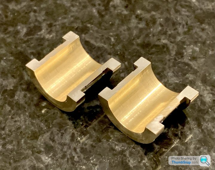
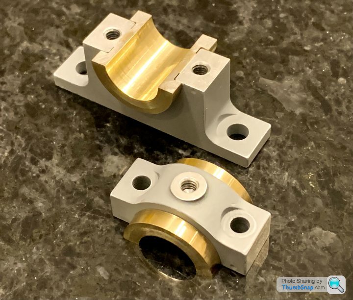
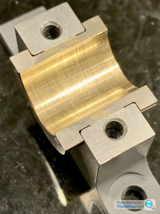
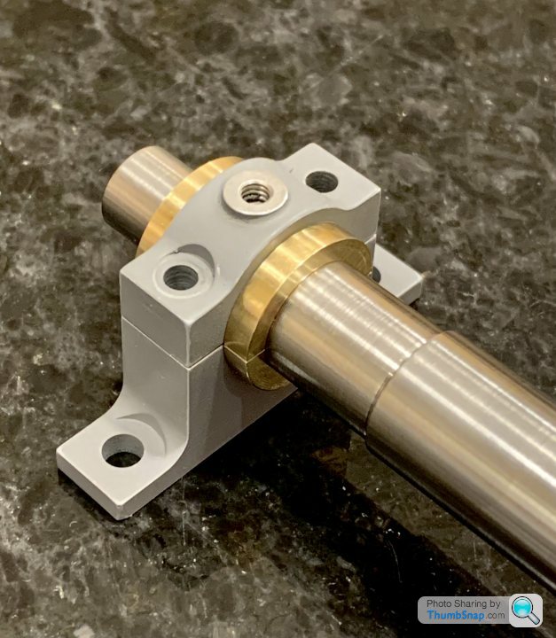
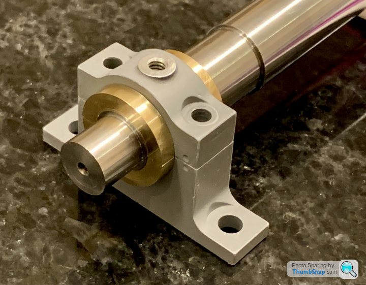
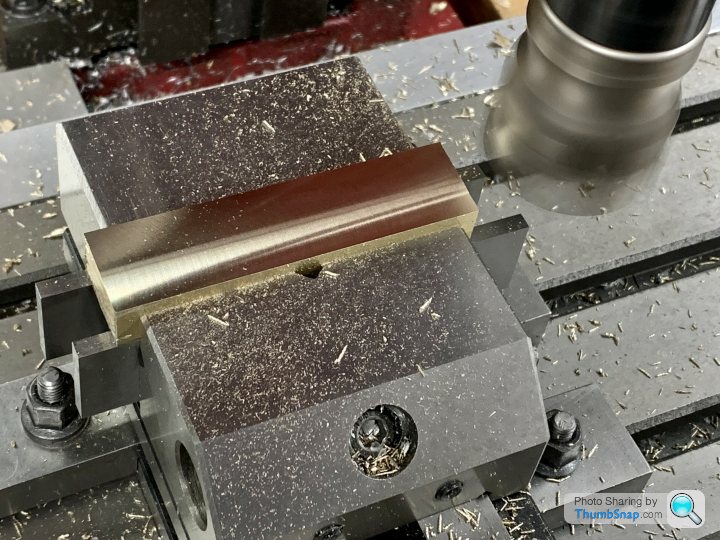
Got the other bearing made this afternoon. It was easier the second time around. I incremented the tool until it was the right fit, but this time I used the top slide dial to maintain a constant width side-to-side. I should have done that before, but I find that if I've been away from the workshop, it takes a while to get back into thinking things through properly. I also opted to make the flanges oversize in terms of width, and then faced to size on a mandrel. I did it this way becasue I found it very difficult to measure the flanges while grooving the slot and then parting off. It turned out that the first pedestal I made, which ended up scrap, was actually very useful in clamping the shells together while doing all this: So these are they:
The running fits seem fine, but I can't help thinking the surface finish could be better on the journals and shaft - it's pretty smooth in rotation, but if it's moved axially...I can tell it's been turned. Anyway, I think it's OK overall. |
| 10/03/2023 13:53:18 |
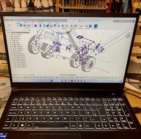
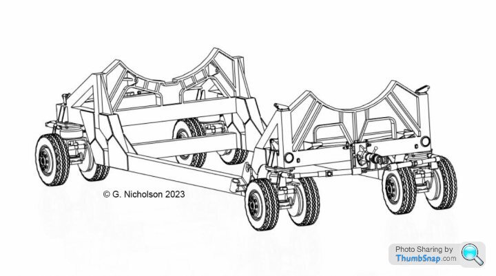
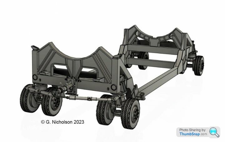
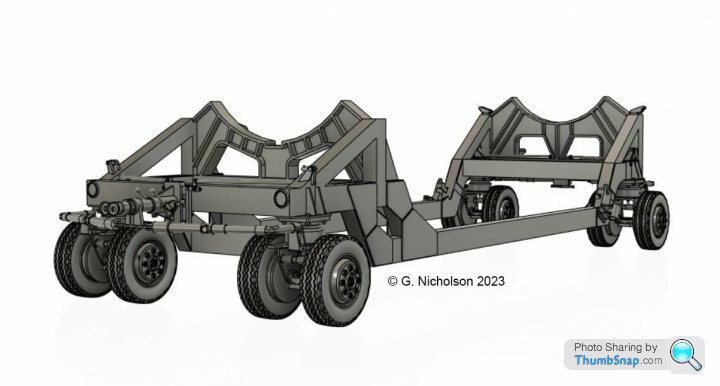
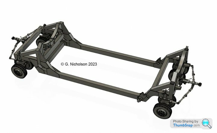
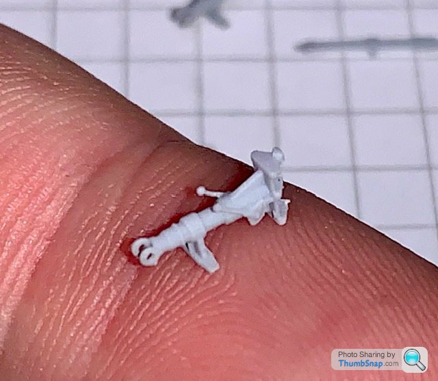
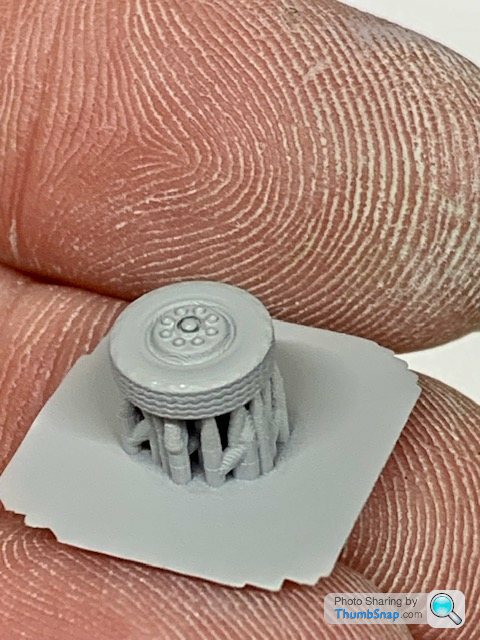
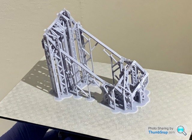
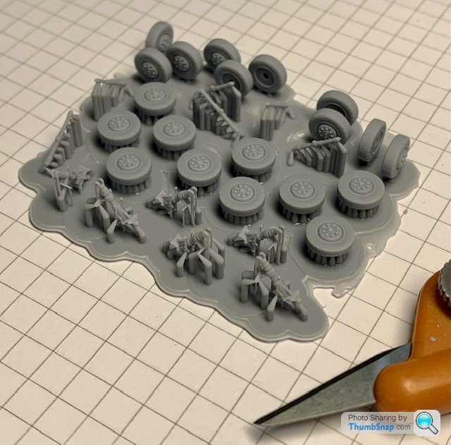
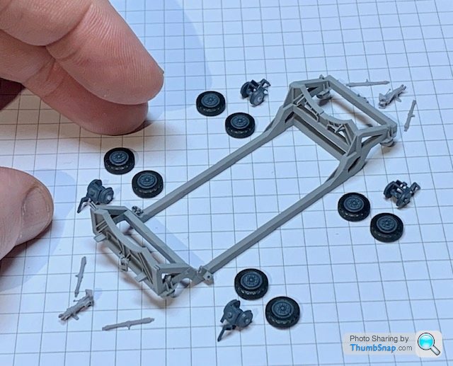
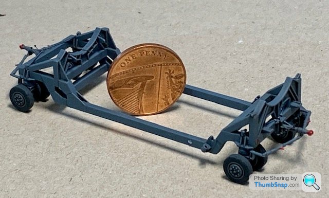
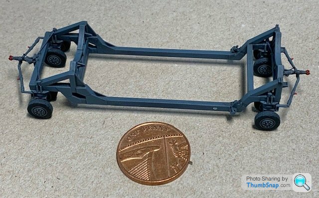
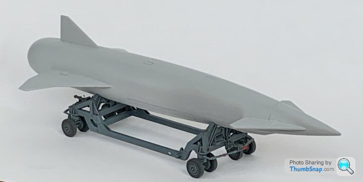
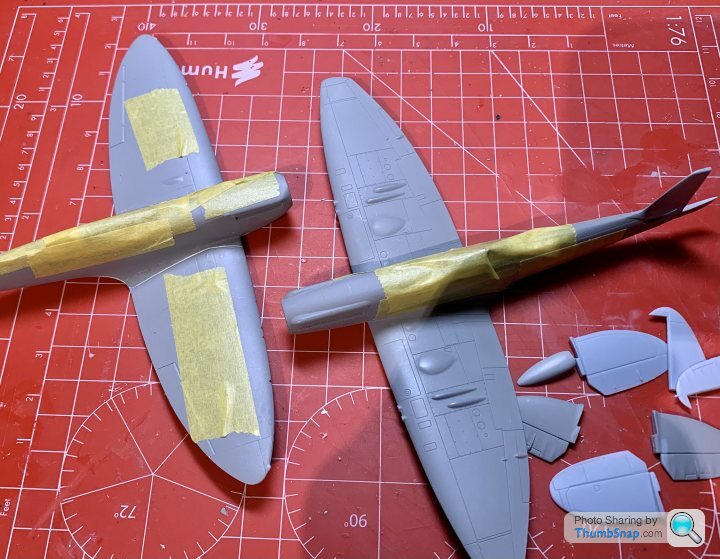
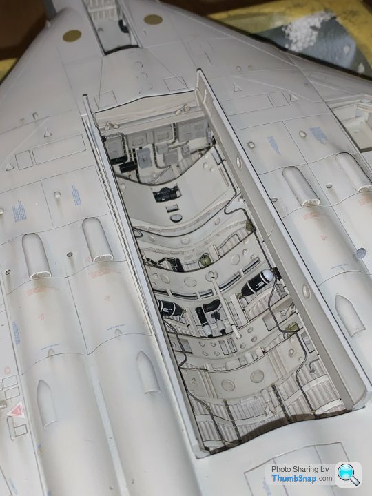
Thanks both - they are 1:72 Spitfires. The Mk1 panel lines are horribly deep, so I'm experimenting with partially filling them with surfacer. The Mk.22 has a horribly moulded nose, which required a lot of flatting, filling and re-scribing to get right. I got a resin printer for Christmas, and I CADded up a trolley for the Blue Steel missile included with the Vulcan (I also made some bomb-bay parts for the Vulcan on it). I scaled online photos and got some key dimensions from a museum. I was quite pleased for a first attempt. I was considering mounting the Vulcan vertically on a wooden base, supported by four acrylic or stainless steel rods up the jet pipes.
Edited By Dr_GMJN on 10/03/2023 13:54:02 |
| 10/03/2023 09:01:49 |
Yes, I’ll have to check what size hole is in the cap. It might be 1.5mm |
| 10/03/2023 08:25:14 |
Posted by Ramon Wilson on 10/03/2023 07:59:08:
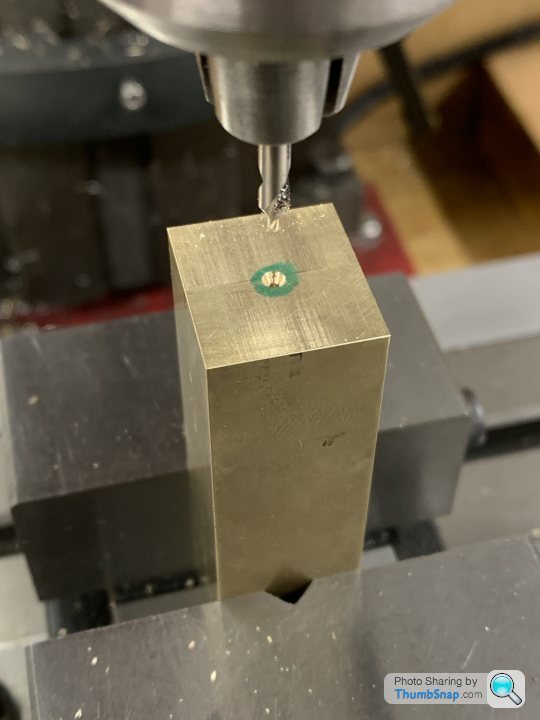
Good result Doc Thanks Ramon. I really did pick a good time to start again -3 forecast for this evening… I still need to drill the oil and anti-rotation holes. May have been discussed, but plan is to assemble, put in the mill and drill a 1mm hole through everything from the top (aligned with the existing oil hole in the cap). If the drill won’t reach the bottom I’ll have to remove the cap and then go through the bottom shell and housing with a drill appropriate for whatever brass or steel rod I can find. Then tap the rod into the housing with Loctite.
|
| 09/03/2023 23:16:12 |
So, deep breath, and try again… |
| 09/03/2023 16:21:26 |
Posted by JasonB on 09/03/2023 15:53:09:
Well if they are bored tighter than optimum they will still be tight on assembly
|
| 09/03/2023 15:46:01 |
Ramon, Jason, OK so as I see it, if I bore the bearings to be a good fit (maybe a little tighter than optimum for now), then even after separation, the bores will be cylindrical (but individually not full half cylinders), and obviously exactly the same diameter they were before separation, and will therefore still match the shaft. So on re-assembly after removing the solder, assuming the bearing was an accurate fit in the housing, no further work should be required, since the only change would be a gap between the bearing faces - the cap-pedestal gap would still be zero on tightening? If the bearings were to wear, then the cap faces could be thinned, allowing the bearings to be tightened? But, in full-size practice, the caps would be thinned by default and shimmed back to size initially, since this would simplify maintenance (no machining, just shimming)? This would make sense.
|
| 09/03/2023 13:35:03 |
Thanks Ramon. Looking back over the discussions on the shaft etc. before I had a break, I honestly can’t remember all the suggestions and pros and cons of shaft first/bearing first. The thread got rather disjointed with me going from one job to another for some reason. Anyway, somehow I ended up with shaft first. I’m happy I can bore the bearings to be a tight running fit on the shaft, ready for lapping when everything is in place on the beds. But…splitting the bearings and removing the solder will inevitably make them tighter on the shaft when re-fitted, and, effectively the mating faces will be slightly higher in the pedestals and caps. I guess I will need to flat the housing faces to suit, and as IIRC Jason and/or yourself said - use the bearing cap lock nuts to adjust? I think that’s the theory, and really the only way to maintain a true cylindrical journal on assembly (even if it’s not a complete cylinder)?
|
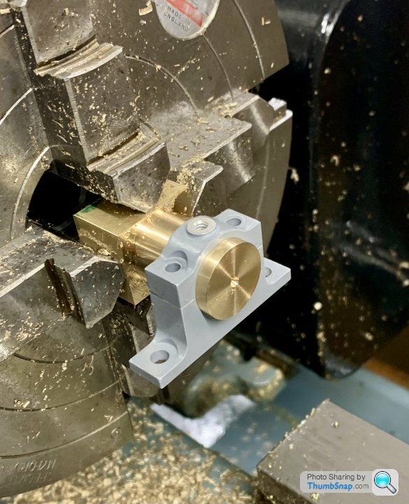
| 09/03/2023 12:18:03 |
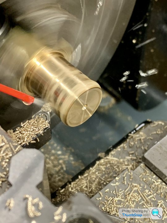
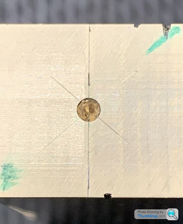
Thanks all. Firstly, I was puzzled by the off-centre drillings, so I took the part out of the chuck and checked again. I think they are fine; it must have been the angle the photo was taken at: I don’t have a boring head for the mill, but even if drilling almost to size, as mentioned, wouldn’t subsequent use of a tight fitting or expanding mandrel in the lathe then defeat the objective of retaining some radial clamping? I’d have thought using the 4-jaw for the entire process would be less risky in terms of the part coming apart? |
| 09/03/2023 08:13:18 |
Hopper - I made the previous two without much problem. IIRC the solder failed, but it was close to the jaws so turning the OD wasn’t an issue. The only problem we’re the tapered walls with the old parting tool. If I shorten the bar and do each bearing separately, the chuck would approximate a milling vice, and I’d also know the OD and ID were concentric. BTW Jason, the hole in the chuck won’t allow the bar to pass through. |
| 09/03/2023 07:43:11 |
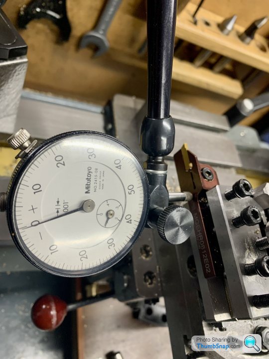
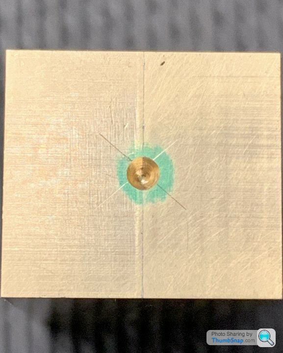
Thanks guys. Yes, looks like one of the drillings isn’t on the line. It’s odd because I used an edge finder to get the centre for drilling (the thicknesses of the bars was identical) and then a dti on a centering rod in the lathe, plus checked the faces with the dti as a double-check, and all was good. Anyway, well spotted.
|
| 08/03/2023 23:32:32 |
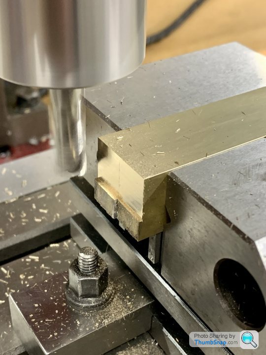
Hmm just wondering if I should saw the block in half to get less overhang, and do each bearing in separate set-ups? I centre-drilled each end to give me that option. |
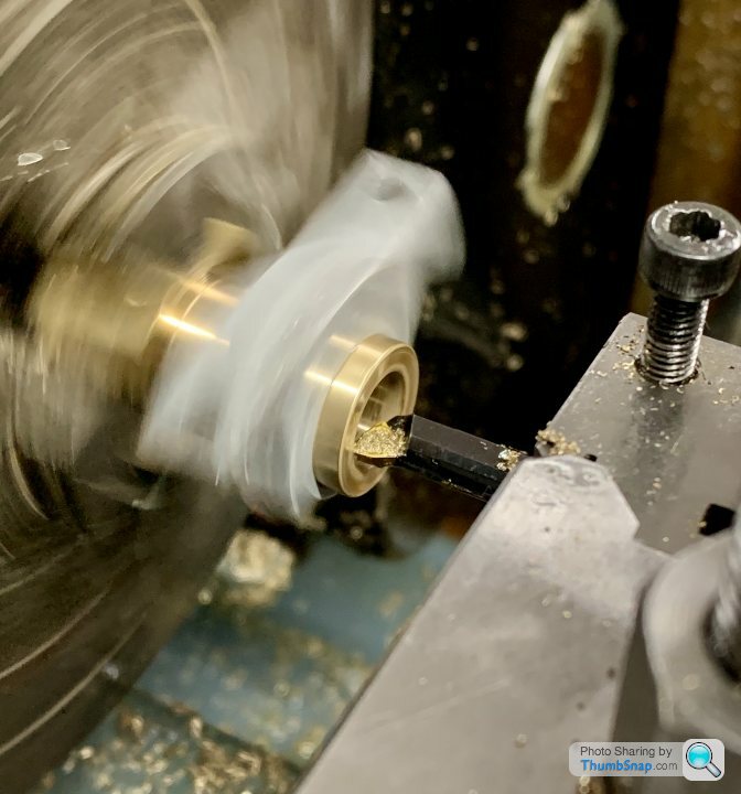
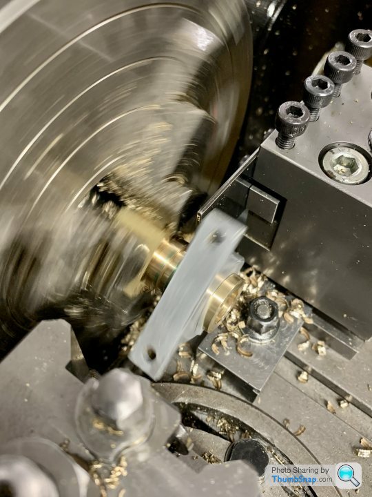
| 08/03/2023 20:14:44 |
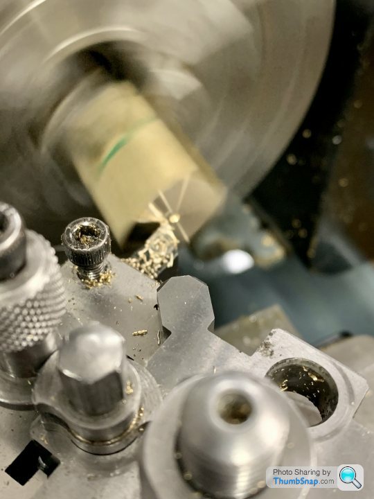
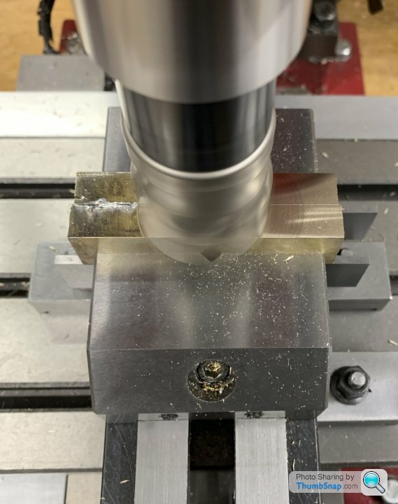
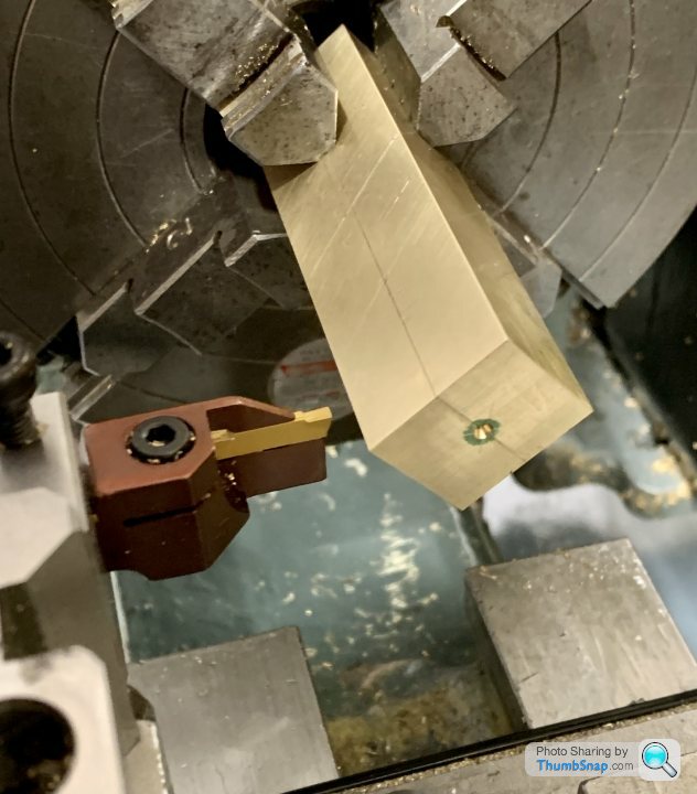
Soldered the bars together, milled them square and centre drilled them. Then back into the 4-jaw chuck ready for some action with my shiny new (non-tapered) grooving tool: |
| 08/03/2023 09:29:27 |
Thanks guys. Good idea with clamping the outside Jason. I’ll do that. |
| 07/03/2023 22:53:37 |
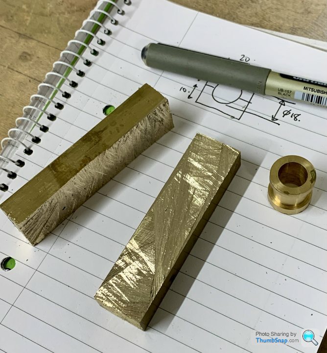
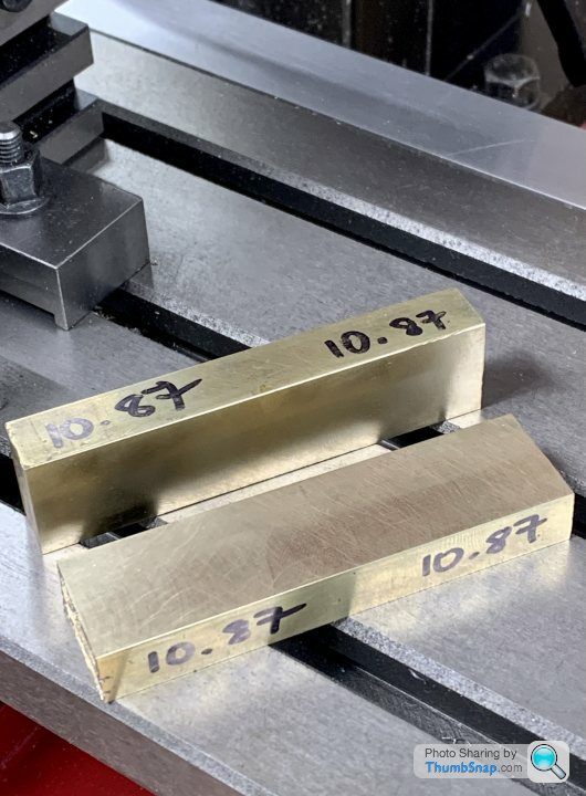
So after getting a bit demoralised over the bearing error after all that work (about 6 months ago - time flies) this evening I started again from scratch: cut the new brass bar to approximate size with the hacksaw: |
| Thread: Harrogate Model Engineering Exhibition |
| 07/03/2023 19:25:48 |
Posted by bernard towers on 07/03/2023 13:56:59:
Looks like the weather could be a dampner Indeed. Snow. Strange they chose winter for a show that appears to have significant outdoor content. |
| 07/03/2023 13:24:55 |
I'm hoping to go on Saturday. Just wondering: how come it's on a Friday and Saturday? Why not over the weekend? |
| Thread: Dead-Blow Hammer Recommendations Please |
| 06/03/2023 15:07:39 |
Posted by JasonB on 06/03/2023 14:45:27:
The do make a smaller size A with 25mm dia ends. Are you hitting the work after tightening the vice, if it is just nipped up then you are more likely to get things jumping about as well as getting jaw lift when finally tightened.
OK I'll have a look for the 25mm Thor Hammer. The work is usually nipped up, but not fully tight. It seems to sometimes seat on one side, but not the other, and takes a few ever lighter taps side-to-side to seat it (sometimes I can hear when everything is seated OK). I thought that something with less spring might make it easier and less hit-and-miss. It's like every time the vice is tightened, it can very slightly displace the work, and when I'm trying to get something square, it's a pain. By the time the vice is fully tight, there's always that bit of doubt left that something hasn't lifted. I'm probably chasing an irrelevant issue, but the more I do, the more I'm aware of what might go wrong. Plenty of times I've milled something supposedly square, and it's not quite spot-on for some reason. During the winter when it's too cold to work in the garage, I occasionally watch YouTube videos on machining like this one: The Best Mill Tip You Will Ever Get --WATCH THIS ENTIRE VIDEO-- - YouTube The next job for me is to re-make the split bearings for the PR, so it seemed kind of relevant. I think there's an Model Engineering show at Harrogate next Friday and Saturday (strange two days to choose), so I'll see if there's anything there. Thanks.
|
| 06/03/2023 14:03:03 |
The Smallest Thor hammer I've got is a No.1 I'd think that there's some correlation between the mass of the shot in the head, w.r.t. the mass of the head itself which determines how effective it is in eliminating rebound? As I got the Narex hammer out of the box an shook it about to hear the shot, I pretty much knew there and then that it would be useless. You can feel it's just too light overall, and it sounds like there's just a pinch of salt in the head. For me, the rebound of the hammer isn't the problem per se, it's that the workpiece can rebound and un-seat itself from the vice (or whatever) as a result of the impact. My assumption was that a decent dead blow hammer would remain in contact with the job, and stop the workpiece rebounding as well. Just like if you drop a steel ball onto a couple of flat plates, the whole lot would jump up, whereas if you dropped an equivalent mass of rough steel granules in a bag on the plates, they wouldn't. Anyway, my dead-blow hammer experience is now over. As someone suggested, I might try and design my own.
|


Magazine Locator
Want the latest issue of Model Engineer or Model Engineers' Workshop? Use our magazine locator links to find your nearest stockist!
Sign up to our Newsletter
Sign up to our newsletter and get a free digital issue.
You can unsubscribe at anytime. View our privacy policy at www.mortons.co.uk/privacy
Latest Forum Posts
- hemingway ball turner
04/07/2025 14:40:26 - *Oct 2023: FORUM MIGRATION TIMELINE*
05/10/2023 07:57:11 - Making ER11 collet chuck
05/10/2023 07:56:24 - What did you do today? 2023
05/10/2023 07:25:01 - Orrery
05/10/2023 06:00:41 - Wera hand-tools
05/10/2023 05:47:07 - New member
05/10/2023 04:40:11 - Problems with external pot on at1 vfd
05/10/2023 00:06:32 - Drain plug
04/10/2023 23:36:17 - digi phase converter for 10 machines.....
04/10/2023 23:13:48 - More Latest Posts...
- View All Topics
Support Our Partners


Shopping Partners
Subscription Offer

Latest "For Sale" Ads
- Reeves** - Rebuilt Royal Scot by Martin Evans
by John Broughton
£300.00 - BRITANNIA 5" GAUGE James Perrier
by Jon Seabright 1
£2,500.00 - Drill Grinder - for restoration
by Nigel Graham 2
£0.00 - WARCO WM18 MILLING MACHINE
by Alex Chudley
£1,200.00 - MYFORD SUPER 7 LATHE
by Alex Chudley
£2,000.00 - More "For Sale" Ads...
Latest "Wanted" Ads
- D1-3 backplate
by Michael Horley
Price Not Specified - fixed steady for a Colchester bantam mark1 800
by George Jervis
Price Not Specified - lbsc pansy
by JACK SIDEBOTHAM
Price Not Specified - Pratt Burnerd multifit chuck key.
by Tim Riome
Price Not Specified - BANDSAW BLADE WELDER
by HUGH
Price Not Specified - More "Wanted" Ads...
Get In Touch!
Do you want to contact the Model Engineer and Model Engineers' Workshop team?
You can contact us by phone, mail or email about the magazines including becoming a contributor, submitting reader's letters or making queries about articles. You can also get in touch about this website, advertising or other general issues.
Click THIS LINK for full contact details.
For subscription issues please see THIS LINK.
Digital Back Issues


Donate

 Register
 Log-in
Model Engineer Magazine
- Percival Marshall
- M.E. History
- LittleLEC
- M.E. Clock

ME Workshop
- An Adcock
- & Shipley
- Horizontal
- Mill

Subscribe Now
- Great savings
- Delivered to your door

Pre-order your copy!
- Delivered to your doorstep!
- Free UK delivery!