Member postings for Dave S
Here is a list of all the postings Dave S has made in our forums. Click on a thread name to jump to the thread.
| Thread: Very small holes |
| 30/07/2022 17:54:32 |
Drill 1mm and then make yourself a single flute drill from silver steel, also known as a d-bit. Or make a 1.48mm spade drill. Watch makers use them, so a bit of Google in that direction will show you how to make them. |
| Thread: Loco transmission |
| 23/07/2022 09:47:28 |
Thinking aloud a hydraulic transmission is a pump supplying pressurised fluid and a turbine turning because of that fluid. is a ‘turbine’ - I’m not a hydraulic transmission specialist but I suspect that is the reason for “no tow”. If so then a couple of 3 way valves and a bypass loop would solve it - loop the input and output of the wheel end hoses together and isolate that loop from the main pump. Not sure that is helpful, but who knows. Dave |
| Thread: Looking for an experienced machinist / toolmaker in Leeds |
| 17/07/2022 13:44:20 |
Don from Suburban tools does some good videos on YouTube. Also check out the Abrasive Machining sub forum on Practical Machinist Dave |
| Thread: Warco Universal Cutter Grinder |
| 27/06/2022 15:16:56 |
Jim, IIRC (it’s been a while) the spindle comes to pieces quite easily. I would take the back off and have a look at the index ring. It’s a fairly chunky piece and there is a good chance the dot mark place is on it. The Deckel head is the same, but IIRC there were detail differences. Dave
|
| 27/06/2022 14:44:48 |
the index dot indicates that the indexing ring is 90 degrees into the 180 degree travel. That gives you the correct position when you line the flat of the d bit up with the pull out blade to rotate the back edge for grinding the relief. There is probably an index notch that corresponds which you can use to lock it whilst making the marker. Have you dismantled the spindle? It possible the index ring has a place for the dot on it, but the hole in the housing to view it hasn't been drilled. Dave |
| Thread: Target for This Month: A 3D Printed Engine |
| 27/06/2022 08:27:42 |
Posted by SillyOldDuffer on 26/06/2022 13:21:34:
Always been concerned about the strength of printed engine components. Partly because PLA is about 10% the strength of mild-steel, and partly because this type of 3D print isn't solid and I don't know how to control the internal web. The slicer software can be ordered to increase the density of the entire internal structure but I only want more plastic at defined weak points like the crank end.
Hobby Slicers are pretty 'general purpose''. The hollow things out because in general a machined design would be solid and that takes ages to print. Often a hollow thing is 'sufficiently not shit' to be useable - especially for the general 'landfill ready' prints a lot of people make. If you reframe a little: if you were designing this as a set of castings you would model all the cores and wall thicknesses exactly as you want them. Think of 3D printing as extremely slow casting process with a digital mould and maybe you need to do the design of the parts a little different. When I did some design for a 3D printed prototype I did all the internal work in the CAD and sent the print out (this was 15 odd years ago) to get made as per design. These were SLS Nylon, but the principle is the same - if it needs to be a specific shape or wall thickness then the generic slicer hollow fill is unlikely to be the best option.
Dave
|
| Thread: How to machine out a metal channel by hand? |
| 24/06/2022 16:47:20 |
Might be easier to make new hoops for the horse end. Dave |
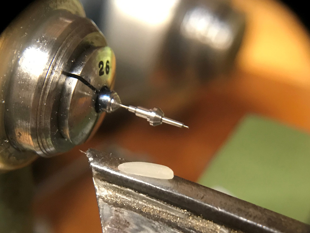
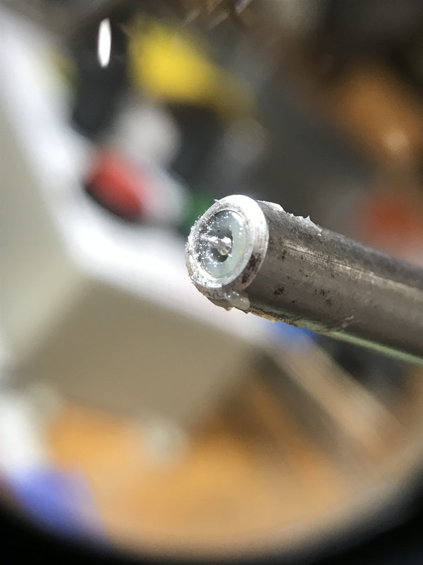
| Thread: Parting off small screws - well, it may be new to somebody |
| 16/06/2022 20:21:12 |
|
| Thread: Target for This Month: A 3D Printed Engine |
| 10/06/2022 16:26:34 |
Yep uni flow is what I meant. Given a 3D printed piston and 3d printed cylinder there is likely to be quite a poor seal, so the compression isn’t likely to be good. Dave |
| 10/06/2022 12:56:25 |
As your printing it it is no more effort to make a twin or even 3 cylinder engine. This simplifies the double acting issue by making it a sum of singles. something like a 3 cylinder radial might work nicely. Have each cylinder somewhat like a CO2 engine - input valve at the top, exhaust through a slot at the bottom. vale can be a simple ball and seat or some sort of print in place flap, triggered by a pin extension on the piston. wouldn't be a 'traditional' engine, but then isntt that the point?
Dave |
| Thread: What are the best quality needle files? |
| 27/05/2022 10:31:26 |
I use a couple of sets of smaller diamond files from Arc for HSS (and carbide as it happens) Dave |
| Thread: T-slot cutter |
| 19/05/2022 20:41:00 |
Yes to photos. I can’t picture what you made. Sounds useful Dave |
| Thread: making a Square |
| 12/05/2022 19:37:22 |
Surely the point is to make things?
Dave |
| 11/05/2022 21:35:48 |
Im building a CNC mill, and I think Ill need a chunkier square when I eventually get to the aligning stage. I came across a webpage sometime ago (can't find it now of course) that showed how to make one from a chunk of cast iron. Not having a lump of iron the right sort of shape I poke about and found some thick walled steel box section. Hurrah, that'll do to try the process at least, and might even work for the intended job To start the long edges are made parallel. Fortunately I have a reasonable surface grinder, so I slapped the box onto the mag chuck and started making sparks:
The weld seam was something like 0,004 lower that the edges. Not too bad. I planned to rough grind and then finish, so once both sides had cleaned up I checked it on the surface plate. Basically zero movement on a 0.0001" DTI. I was well chuffed Now the long edges parallel It was time to rough in the ends. I hacksawed them roughly square, whacked it in a known OK grinding vice and made some more sparks:
Then with parallel ends that should be close to square it was back to the surface plate to measure up:
DTI on a surface gage rocked left and right for the high reading. Turned out to be leaning by about 0.007". For the first round of squaring up it was back to the grinder with some feeler gages:
0.003" under one side and clean up one end, then flip and make parallel (without the feelers). At this point I left it to sit for a couple of days, partially to let it move if it was going to, and partially cos I have other things to do... It did move, and the long sides were slightly out, something like 4 tenths IIRC. So I did a light set of finish passes on them. This is the start of one ( the beautiful dark corner):
Ended up back to basically as good as I can measure Then another round of measure the squareness. I couldn't easily get the round part of the surface gage to touch and have the DTI at the height I wanted due to the way the angles worked out. Fortunately the surface gage has a V in the front, so one bearing later I have a round bumper again and I could measure over pretty much the full height.:
This time I needed an offset with precision in the tenths region, so I made a pair of gage block stacks with the required offset ( IIRC it was 0.2 on one side and 0.2014 on the other). The square was supported on these on the grinder, mag'd and clamped so I didn't get any ideas about flying away and then a fresh dress and a light grind and I cleaned up the ends. The finished square has come out OK:
Its roughly 90 degrees Dave
Edited By Dave S on 11/05/2022 21:36:28 |
| Thread: J & S surface grinder - refurbishment |
| 11/05/2022 17:06:45 |
I would probably TIG or braze up the holes - but I have a TIG set and like to use it JB weld might also be an option Dave |
| Thread: Jones and Shipman 540 plain bearing head seals |
| 06/05/2022 08:16:03 |
Yes indeed. I was hoping to get the seals before having to strip the machine. Still if no one knows then I guess that’s how it’ll go. |
| 05/05/2022 08:49:42 |
All I have is a photo of the parts manual, which has a very general description:
Of course the part numbers are no use unless you can get them from the apparently defunct J&S. Given the cost of the wheel head oil Id rather not run a total loss system... Dave
|
| 04/05/2022 19:53:32 |
My elderly 540 has decided to start leaking from its wheel head. It’s the plain bearing, uses super thin oil model. Andmar suggested a seal place, but the info in the parts manual is apparently not sufficient. Dave |
| Thread: METAL DUST & VFDs |
| 02/05/2022 11:26:21 |
I would put it in a box with filtered forced air cooling. doesn’t need to be fancy filters, just something to stop the brass - a panel filter for a car engine might be what I’d use as I have them available. Even a pair of tights from swmbo over a tube would work. Dave |
| Thread: making spindle bearings |
| 02/05/2022 11:18:41 |
What are you making a spindle for? Dave |


 - I calculated it to 89.996 / 90.004 based on the measurements. Ill check it again in a few weeks to see if it moves, but even if it does it'll likely be close enough for what I need.
Magazine Locator
Want the latest issue of Model Engineer or Model Engineers' Workshop? Use our magazine locator links to find your nearest stockist!
Sign up to our Newsletter
Sign up to our newsletter and get a free digital issue.
You can unsubscribe at anytime. View our privacy policy at www.mortons.co.uk/privacy
Latest Forum Posts
- *Oct 2023: FORUM MIGRATION TIMELINE*
05/10/2023 07:57:11 - Making ER11 collet chuck
05/10/2023 07:56:24 - What did you do today? 2023
05/10/2023 07:25:01 - Orrery
05/10/2023 06:00:41 - Wera hand-tools
05/10/2023 05:47:07 - New member
05/10/2023 04:40:11 - Problems with external pot on at1 vfd
05/10/2023 00:06:32 - Drain plug
04/10/2023 23:36:17 - digi phase converter for 10 machines.....
04/10/2023 23:13:48 - Winter Storage Of Locomotives
04/10/2023 21:02:11 - More Latest Posts...
- View All Topics
Support Our Partners


Shopping Partners
Subscription Offer

Latest "For Sale" Ads
- Reeves** - Rebuilt Royal Scot by Martin Evans
by John Broughton
£300.00 - BRITANNIA 5" GAUGE James Perrier
by Jon Seabright 1
£2,500.00 - Drill Grinder - for restoration
by Nigel Graham 2
£0.00 - WARCO WM18 MILLING MACHINE
by Alex Chudley
£1,200.00 - MYFORD SUPER 7 LATHE
by Alex Chudley
£2,000.00 - More "For Sale" Ads...
Latest "Wanted" Ads
- D1-3 backplate
by Michael Horley
Price Not Specified - fixed steady for a Colchester bantam mark1 800
by George Jervis
Price Not Specified - lbsc pansy
by JACK SIDEBOTHAM
Price Not Specified - Pratt Burnerd multifit chuck key.
by Tim Riome
Price Not Specified - BANDSAW BLADE WELDER
by HUGH
Price Not Specified - More "Wanted" Ads...
Get In Touch!
Do you want to contact the Model Engineer and Model Engineers' Workshop team?
You can contact us by phone, mail or email about the magazines including becoming a contributor, submitting reader's letters or making queries about articles. You can also get in touch about this website, advertising or other general issues.
Click THIS LINK for full contact details.
For subscription issues please see THIS LINK.
Digital Back Issues


Donate

 Register
 Log-in
Model Engineer Magazine
- Percival Marshall
- M.E. History
- LittleLEC
- M.E. Clock

ME Workshop
- An Adcock
- & Shipley
- Horizontal
- Mill

Subscribe Now
- Great savings
- Delivered to your door

Pre-order your copy!
- Delivered to your doorstep!
- Free UK delivery!