Member postings for Robert Trethewey
Here is a list of all the postings Robert Trethewey has made in our forums. Click on a thread name to jump to the thread.
| Thread: Dividing head advice |
| 14/04/2022 23:05:12 |
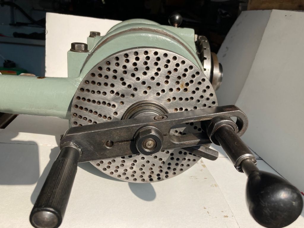
It's been pointed out to me that there are at least two glaring errors in my latest thread 4in Dividing Head - the first being that the label rivited to the outter edge of the plate says 1 division = 1 min (not 1 mm) the second is that the two chamfered holes that lock the plate in place ate 6.3mm dia not 3.3mm dia. Sorry for any confusion. I've had one reply saying that "why cant I produce the plates myself" - no reason why if I knew the combination of holes in each plate. Edited By Robert Trethewey on 14/04/2022 23:06:47 |
| 14/04/2022 10:27:17 |
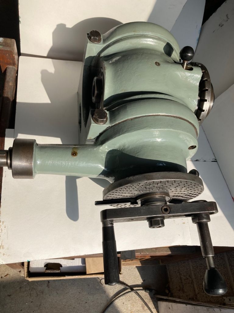
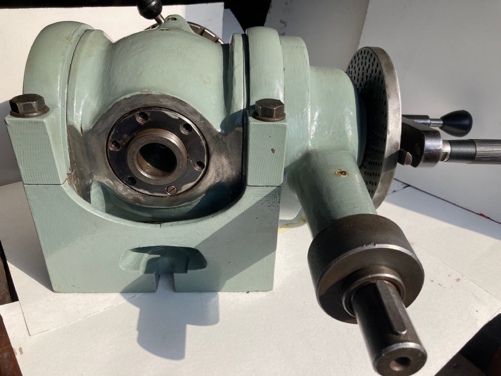
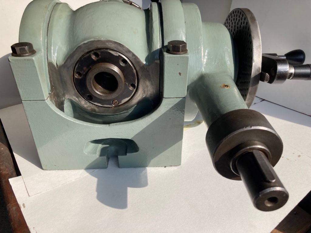
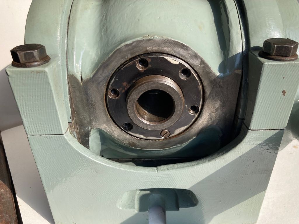
Hi: Can anyone please help me identify the Dividing Head shown in my latest album 4in Dividing Head the item I'm most interested in is finding out if anyone knows where I can find new or used pin plates to go along with the number 3 plate that came with the DH when purchased. The DH is a 4in the pin plate is 123.6mm dia. and has a knurled edge with a black plate pinned on the outside circumference saying each division =1mm the plate is 5mm thick it has a 30mm inside dia. the number 3 plate has 4 sets of drilled holes 40, 37, 36 and 29 holes. The plate is attached to it's backing piece by two chamfered screws the holes are 3.3mm dia. and have a 42mm PCD
|
| 27/03/2022 14:30:32 |
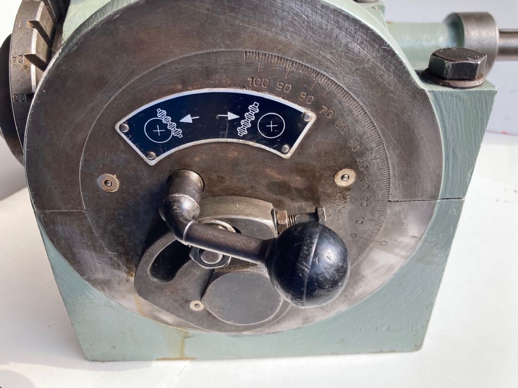
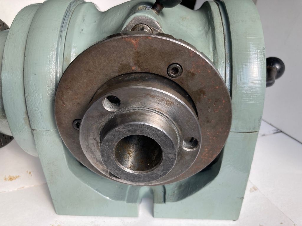
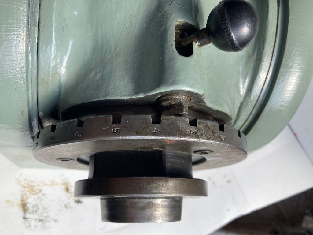
I recently purchased a 6in dividing head and and have stripped and rebuilt it - However the original manufacturers nameplate had the name rubbed off - please can anyone identify for me the original manufactrurers name as the name plate says Made in Spain the part number is D1494A and it appears to be a Hoffmann type unit it weighs 50Kg it has a double sided plate with hole circles ranging from 49 down to 15 holes per circle it has a DIN 55022 or DIN 55027 faceplate see attached images 24 stop positions and power feed via 25mm shaft 6mm key My album Robert Trethewey (6in Dividing Head Rebuild)
|
| Thread: Eagle Surface Grinder - weight of parts |
| 08/12/2021 19:43:37 |
I've checked the cross and vertical screws for accuracy and found them both within acceptable limits once I've removed the backlash - did you do anything about the backlash on your machine. My machine when being stripped for rebuild is painted BT call box red internally but grey externally was your machine similarly painted. Bob Trethewey |
| 08/12/2021 17:05:03 |
I'd say these were very accurate - In bringing an Eagle SG made by Dronsfield back from it's previous owner I had to triple brace my hoist to lift the machine off a pallet I'd bolted it to for transport. That would make it on or just under 375Kg Does anyone know when these machines were made as I've just acquired a Model 3 serial no 3628 I'm assuming that makes it their series 3 number 628 of that series. Bob Trethewey - Audiologist Shillingstone Dorset |
| Thread: Myford VM-C Milling Machine |
| 19/05/2021 06:23:04 |
Would anyone out there have information on the supply of metric longditudinal leadscrew nuts for the Myford VM-C series of mill - my nut is worn and does need replacement it's a 4mm pitch right hand thread ACME the LS is 25.33mm in dia. |
| Thread: Myford 254V Plus gearbox noise and vibration |
| 07/11/2020 18:58:02 |
Hi: Thanks for coming back to me so quickly - I don't have anything to measure the vibration. I can hear and feel a very slight knocking - this is why I looked up posts about bearing setup and adjustment thinking it was a loose bearing which could be the case as the previous owners, a technical college in London, who's engineers had done little or no maintenance since the machine was first supplied to them. |
| 07/11/2020 16:39:30 |
Hi: Everyone - on the 2nd of May 2019 IFoggy wrote that he'd found a small piece of iron in one of the gears of his Myford 254V Plus lathe which caused a vibration when using the lathe's back gear - I'd very much appreciate knowing how he actually found the offending piece of metal as I may have a similar problem effecting my machine to a small amount but I'd like to ensure that this doesn't develope into a real problem. My Myford 254V plus can be seen on www.ritasears.blogspot.com look at tab "R" if you're interested in seeing the rebuild of a Myford KF-MC-C milling machine which will shortly be fitted with a three axis DRO and a home built power drive on it's longitudinal table look at tab"O"
|
| Thread: Servicing a Myford 254 |
| 07/11/2020 16:18:08 |
Hi: everyone - on the 2nd May 2019 Ifoggy wrote that he'd found a small piece of iron in one of his gears which caused a vibration when using the lathe's back gear - can Ifoggy please expand how he found this offending piece of metal please as I believe that I have a similar problem and I would like to find out if I can service the machine before any major damage is done.. My 254V can be seen on www.ritasears.blogspot.com and check out Tab "R" if you're interested in seeing the rebuild of a Myford KF-VM-C milling machine which will shortly be fitted with three axis DRO and a home built power drive on its longitudinal table look at tab "O"
Thanks for your comment in advance - best regards Bob Edited By Robert Trethewey on 07/11/2020 16:43:37 |
| Thread: ML7 motor - Tyco Crompton - wiring/burnt out? |
| 04/04/2018 10:43:58 |
Perhaps this image may well assist you - please look up ritasears.blogspot.co.uk and go to the workshop tab then go to the bottom of the page last image should be what you're looking for. If you by chance have a coolant pump which has a 4 position switch on the electric motor top and could send me an image of the internal wiring I'd be so grateful. Bob Trethewey |
| Thread: Myford 254+ Wiring |
| 30/03/2018 17:19:19 |
Help needed please. The coolant pump has a 360 deg 4 position switch on its cast casting 2 on positions and 2 off positions I recently stripped the pump to replace both pump shaft bearings taking photos of the wiring as I stripped it apart - down loaded onto my laptop after waiting for the new bearings to arrive I finally rebuilt the pump. In the meantime my laptops HD failed and although it eventually shows me a desktop that as far as it goes I can't get to the file where the images are to show me where the wires go on the switch - had to buy a new laptop. I've got three wires that come from the motor winding 1 red 1 yellow and 1 black, I've two wires from the Capacitor 1 Blue and 1 Brown then I've the power cable normal 1 Yellow green earth 1 Brown Power and 1 blue negative The central switch has 4 positions 2 on and 2 off The switch has 5 terminals on one side 1 and 2 on the other side 3,4 and 7 when off nothing connects when on 1 connects with 2 and 3 connects with 4; 7 doesn't seem to connect with anything Can anyone help please regards |
| Thread: Issue incorrectly identified Feb 17 and March 17 both No 251 |
| 11/05/2017 17:14:38 |
Fellow followers of Model Engineers Workshop Today I received Model Engineers Workshop number 251 March 2017 the same number and February's issue. Two months late and I am still to receive the issue 255 for June 2017. Is this shambolic distribution a regular thing with the publishers? Please inform me if the electronic version is similarly shambolic or is there some form of normality with that publication? Regards Bob Trethewey (dorsetearman) |
| Thread: Warco Minor Mill Modifications |
| 05/06/2016 09:58:09 |
Duncan and Martin I bow to your experience and knowledge. I had not considered the difference in the ratios of the column dia to the fixed distance between the column centre and the spindle centre the difference in the ratios of both multiplying the error achieved.. Thanks to both of you for pointing out alternative thoughts and considerations. I am currently making a new depth gauge/stop which was broken off when I bought the machine, I shall now modify my designs for this to incorporate the dial indicator suggested by Martin. The idea of a laser is useful however the machine would need to be bolted securely to the garage floor to avoid machine creep and this I did not want to do. Regards to both of you for your ideas and suggestions. BobT (Dorsetearman)
|
| 04/06/2016 20:28:00 |
Thank you Vic for your Post I don't think that this mill design suffers from the same amount of wobble that the Warco/Grizzly/Pinnacle type milling machine does. I will, however, read the article with interest. Regards dorsetearman BobT |
| 04/06/2016 19:21:50 |
speech clarity (all one word no spaces) at hot mail dot com will reach me |
| 04/06/2016 18:18:49 |
Reply to Norman Yes. By making a set of drilling jigs so that when the rack has been reassembled, after drilling and tapping the grub screw locations in the rack. Then by locking the head in the axis where it is at 90deg to the horizontal table. Then by using the drilling jigs produce a pilot bore followed by an enlarged hole which may be honed to final size. Then using grub screws with machined cylindrical tips to suit the honed holes in the main column; I should be able to ensure a fairly accurate vertical plane when I raise or lower the head using the rack. If I want to swivel the head I would merely remove the grub screws and allow the head to float as it does now before being locked in position. regards BobT |
| 04/06/2016 14:58:28 |
I'd like to stop my Warco Minor mill from wobbling when the milling head is lifted via its rack. I'd like to place in the rack 2 lower and 3 upper machined grub screws and be able to allow these to locate in holes drilled into the machine main column. Has anyone done this and if so how successful was it in allowing the head to raise and lower whilst staying in the same vertical plane. regards Dorsetearman |


Magazine Locator
Want the latest issue of Model Engineer or Model Engineers' Workshop? Use our magazine locator links to find your nearest stockist!
Sign up to our Newsletter
Sign up to our newsletter and get a free digital issue.
You can unsubscribe at anytime. View our privacy policy at www.mortons.co.uk/privacy
Latest Forum Posts
- *Oct 2023: FORUM MIGRATION TIMELINE*
05/10/2023 07:57:11 - Making ER11 collet chuck
05/10/2023 07:56:24 - What did you do today? 2023
05/10/2023 07:25:01 - Orrery
05/10/2023 06:00:41 - Wera hand-tools
05/10/2023 05:47:07 - New member
05/10/2023 04:40:11 - Problems with external pot on at1 vfd
05/10/2023 00:06:32 - Drain plug
04/10/2023 23:36:17 - digi phase converter for 10 machines.....
04/10/2023 23:13:48 - Winter Storage Of Locomotives
04/10/2023 21:02:11 - More Latest Posts...
- View All Topics
Support Our Partners


Shopping Partners
Subscription Offer

Latest "For Sale" Ads
- Reeves** - Rebuilt Royal Scot by Martin Evans
by John Broughton
£300.00 - BRITANNIA 5" GAUGE James Perrier
by Jon Seabright 1
£2,500.00 - Drill Grinder - for restoration
by Nigel Graham 2
£0.00 - WARCO WM18 MILLING MACHINE
by Alex Chudley
£1,200.00 - MYFORD SUPER 7 LATHE
by Alex Chudley
£2,000.00 - More "For Sale" Ads...
Latest "Wanted" Ads
- D1-3 backplate
by Michael Horley
Price Not Specified - fixed steady for a Colchester bantam mark1 800
by George Jervis
Price Not Specified - lbsc pansy
by JACK SIDEBOTHAM
Price Not Specified - Pratt Burnerd multifit chuck key.
by Tim Riome
Price Not Specified - BANDSAW BLADE WELDER
by HUGH
Price Not Specified - More "Wanted" Ads...
Get In Touch!
Do you want to contact the Model Engineer and Model Engineers' Workshop team?
You can contact us by phone, mail or email about the magazines including becoming a contributor, submitting reader's letters or making queries about articles. You can also get in touch about this website, advertising or other general issues.
Click THIS LINK for full contact details.
For subscription issues please see THIS LINK.
Digital Back Issues


Donate

 Register
 Log-in
Model Engineer Magazine
- Percival Marshall
- M.E. History
- LittleLEC
- M.E. Clock

ME Workshop
- An Adcock
- & Shipley
- Horizontal
- Mill

Subscribe Now
- Great savings
- Delivered to your door

Pre-order your copy!
- Delivered to your doorstep!
- Free UK delivery!