Member postings for SillyOldDuffer
Here is a list of all the postings SillyOldDuffer has made in our forums. Click on a thread name to jump to the thread.
| Thread: A Well-Tempered Hybrid Pendulum Clock Project |
| 06/09/2023 11:18:32 |
Posted by S K on 06/09/2023 03:22:07:
Oh no! The ATMega data sheet section 17.3 describes how pins T0 and T1 can be used as an external clock for the timer/counter registers clkt0 and clkt1. But it's not a direct input, it's actually sampled by the normal system clock! Apparently this is just part of the system-wide I/O synchronization. That being so, you can't have a genuinely independent external timer clock. Bummer! True of the AVR 8-bit chips, not sure it applies to other microcontrollers though. On the AVR's it limits the external clock to 6.8MHz, which is why my 10MHz OCXO has a divide by 2 output as well - I could clock the timers at 5MHz. Not tried it yet because it limits resolution to 200nS. Much better to replace an Arduino's on board 16MHz crystal or ceramic resonator with a stable external oscillator, ideally 16MHz so micros(), millis() and other time functions work normally. The CPU chip has an internal oscillator connected to two pins across which a SMD crystal or resonator is bridged to set the frequency. The chip pins aren't available to the user - instead two short tracks lead to the crystal, which would have to be removed and the new source soldered on. Neither pin is earthed, so the source has to float. Apart from that, I think feeding a signal to the oscillator pins will cause it to work as an amplifier with no complications. Not tried it though. Another possibility is the Arduino Uno, because the CPU is a DIP chip plugged into a socket, making the oscillator pins more accessible. Dave
|
| Thread: Motor HP - Unusual Value on Label |
| 05/09/2023 16:54:06 |
Posted by Andy_H on 05/09/2023 16:02:15:
Posted by noel shelley on 05/09/2023 12:44:20:
0.53a is odd and does not tally with .25Hp ? 180watt would be .25 Hp. I agree. ...But it's about right for .125 HP (Metric) My guess is a stamping mistake - the plate is missing a decimal point and a 1 I expect an apprentice did it! Dave |
| Thread: Pre-Paint Degreasing |
| 05/09/2023 12:04:49 |
Posted by Graham Stoppani on 05/09/2023 06:25:49:
Dan Gelbart is rather dismissive of using solvents to prepare metals for painting. He says a sand blaster, bluing or Ajax, of all things, is best. ...
Suitably chosen solvents are unlikely to damage the surface, whereas abrasives do. Maybe painting implies that scratching and pitting the surface isn't a problem, and it's often done deliberately to provide a key. But abrasives aren't smart if the object is to be anodised. I don't know exactly what's in Ajax or Vim. They're both scouring powders and these contain an abrasive such as chalk with a degreaser such as Sodium Carbonate, and Bleaching Powder (active ingredient Chlorine). I'd avoid using them on light metal alloys - anything containing Aluminium, Magnesium or Zinc. Cleaning is good, corroding is bad! Dave
|
| Thread: A Well-Tempered Hybrid Pendulum Clock Project |
| 05/09/2023 10:27:05 |
Posted by S K on 04/09/2023 20:56:40:
Progress on electronics: ...
For the moment, I'm just using Arduino's internal micros function for the period. It's understood that this is not good enough, and it's already evident that it's incorrect, being a fraction of a percent slow as tested. I'm still trying to decide how I'll do it "for real." The RTC, with 2ppm, is much better, and it has a 32kHz output that I might employ somehow. Otherwise, maybe I'll try hacking the Arduino's oscillator. ... I have a faster Arduino-compatible microcontroller that runs at 120 MHz that I may swap in for the 16 MHz Arduino once things are running properly (it's a bit fussier to use), or else I have a few other considerably faster options on hand that aren't compatible with the Arduino IDE. One of those should improve timing resolution (but not necessarily accuracy)... I've trodden this path already, so this may help:
An example of Arduino code using counter-timers here. Dave
|
| Thread: Pre-Paint Degreasing |
| 04/09/2023 19:57:12 |
Depends on the type of grease, how much there is, and how clean the parts need to be. Often as not a lightly contaminated surface can be cleaned well enough by wiping over with a clean cotton rag soaked in Acetone or isopropyl alcohol. Both should be full strength, not diluted with water. I often wipe with Acetone, rinse under the tap, dry and then wipe over with IPA. This is because some greases are more soluble in Ketones than Alcohols and vice versa. Using Acetone and IPA in sequence is belt and braces. If cleanliness is important, washing in Acetone, followed by washing in IPA, followed by washing in very hot water with detergent, followed by a water rinse, and finishing with an IPA rinse. This isn't always good enough. Viewed through a microscope metal is seen to be full of tiny cracks and caves. Getting grease out of these requires stern measures, perhaps boiling in distilled water with detergent for an hour or two, followed by a sequence of Acetone and IPA washes and rinses. Don't use alkaline degreasers on Aluminium, they corrode the metal. Wear clean rubber gloves, and before starting make sure they aren't attacked by Acetone. It's an excellent solvent, including skin! The best solvents are often low flash point hydrocarbons. Petrol works well, but it's very dangerous. Cellulose Thinners, Acetone and IPA are considerably safer. Diesel gets heavy grease off, but is greasy itself - more trouble than it's worth. I've had mixed results with my ultrasonic cleaner. Dave
|
| Thread: Runout on a collet chuck? |
| 04/09/2023 10:43:11 |
Posted by Andrew Tinsley on 03/09/2023 20:05:36: ... I did use the search function, but didn't come up with a run out figure that was deemed acceptable by the majority of model engineers. ... Apart from the limitations of the search engine, the forum isn't structured as a reference source. Wikipedia is best for that, but you can't have a conversation with it! Wikipedia's article on runout doesn't answer the question either - it's an overview without figures. Maybe we should improve it? There probably isn't "a run out figure that was deemed acceptable by the majority of model engineers", because the answer depends on the nature of the work. Money matters too! A few things I do are crude enough to let me swap ends in a 3-jaw without worrying about the resulting error. Other work demands much more care, usually with a 4-jaw adjusted to the best of my ability. My lathe, chuck, and my Dial Indicator limit the best I can do to about 0.01mm close to the chuck. Long work requires steadies and an accurately adjusted tailstock. For close up only I have an ER collet chuck, which can be carefully centred with the same Dial Indicator, so similar run out to the 4-jaw. My collets are inexpensive, bought from Warco and ArcEuro, and they're all as good as the chuck. I rarely attempt high accuracy work, instead working within the ordinary limits of my equipment, which is something like 0.02mm or a thou. I don't use collets often, but once in a while I do a job with round shafts being repeatedly taken on and off the lathe: when this happens collets are much faster than the 4-jaw. You can guess I don't do much watchmaking or instrument work! If I did, something like a Cowells with a complete set of collets would be needed. Industry have another reason for wanting low TIR collets, especially ER. They spin them very fast, and a slightly unbalanced collet at 30,000 rpm does a poor job. The same collet at 3000rpm would be fine. So I come at run-out by asking 'what do I need to do to get the required result?' Quite often there are alternatives; just as well - I dislike spending money on tooling that's better than my lathe or mill can make use of. However, as Model Engineering is a hobby, others enjoy owning the very best, even if there's no practical need for it. Always nice to have capability and reliable tools, especially if someone else paid for them! Most of us own a mix of more-or-less suitable tools obtained by various methods. Dave |
| Thread: Isochronous knife edge suspension? |
| 04/09/2023 09:41:10 |
My poor old bonehead can't accommodate this stuff so I started drawing it. Didn't get far! Before reaching the nature of the curve described by the bob's centre of mass, I think I spotted a fundamental practical problem. It's slip. Surely the nature of the curve followed by the bob's centre of mass depends on the amount of slip between roller and flat? I think 100% slip would cause the roller to act as a simple hinge - so the pendulum won't be isochronous. To get isochronicity, I believe the roller mustn't slip at all? If that's right I can't think of a way of guaranteeing zero slip. Other practical issues are the:
Though I like David's idea and have merely failed to prove Messrs Huygens and Haines wrong myself, I think the cost of driving a high-friction suspension will outweigh the benefit of the pendulum being closer to isochronous. Nonetheless, I reckon David should build a better engineered version of his 2p proof-of-concept and measure it. My guess is friction will cause more trouble than the swing not being isochronous even if slip doesn't matter. I could be wrong; the experiment needs to tried! Dave
|
| Thread: Compressor question |
| 04/09/2023 08:34:17 |
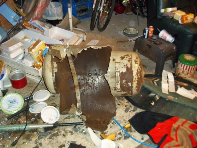
Just a guess but I notice the heads have an air intake at the front, and connect to a shared outlet manifold at the back, which then connects via a big pipe to what could be a non-return valve on the receiver. In addition both heads have thin pipes leading to the top: I suggest these move a valve that directs air back to atmosphere rather than compressing it into the tank. The higher the pressure in the tank, the more air is escapes back out the inlet, greatly reducing the load on the motor. Not an efficient set-up, but it allows the motor to run continuously which is good for reliability because frequent restarts are bad for single-phase motors. I think the compressor is either designed for continuous operation or it predates electrical motor control. Another system uses a clutch to disconnect the pump from a continuously running motor. I wouldn't attempt to modernise it: if it works leave it be. My main concern is the receiver. Air tanks tend to collect water, which causes them to rust inside on the bottom, maybe cutting a groove into the metal along a water line. A tank that's perfect on the outside can be badly damaged inside. Poor maintenance or long-term storage with water inside are widow-makers.
Dave
|
| Thread: JoNo's Pendulum |
| 03/09/2023 21:01:22 |
Posted by Joseph Noci 1 on 03/09/2023 19:41:07:
Posted by John Haine on 03/09/2023 18:00:05: ... Twice mine - Mine obviously is lacking - what is your advice?My first suspect is the stand, because it's an important part of the system:
Try bouncing a laser pointer off a mirror placed on top so that any movement of the stand at the suspension is amplified at the distant dot. Might be interesting as well to measure Q with the stand stood on a soft rug rather than tiled floor. Dave
|
| 03/09/2023 17:40:26 |
Posted by SillyOldDuffer on 03/09/2023 14:25:11:
Had a go at Joe's amplitude data in hope of identifying his decay curve's values... ...Next step is to fit a curve to the envelope and reveal its parameters. First attempt wrong, now looking at scipy.optimise.curve_fit. If only I understood it! Dave A result: From y = a * np.exp(-b * x) + c The parameters are: a = 9.65858457e+02, b = 2.66220695e-06, c = 2.55142704e+01 numpy,exp() documented here. Returns the exponent eᕁ, the inverse of natural log,
The code:
Dave |
| 03/09/2023 14:25:11 |
Had a go at Joe's amplitude data in hope of identifying his decay curve's values. Mixed success, first problem is to extract the envelope of the signal, which looks good. In the graph below, Joe's signal, composed of sinusoidal amplitude readings. is in blue, whilst the envelope retrieved from the signal is in orange.
I expected the orange curve to simply connect the peaks of Joe's data, and it doesn't. Zooming in on the orange line shows it also appears to carry a signal:
Not sure why. Possibly to do with Joe's 20mS sample rate, or a mathematical artefact. Or maybe it's a real-world pendulum imperfection. Dunno. Code so far:
Next step is to fit a curve to the envelope and reveal its parameters. First attempt wrong, now looking at scipy.optimise.curve_fit. If only I understood it! Dave
|
| 03/09/2023 10:18:08 |
Posted by Joseph Noci 1 on 03/09/2023 07:32:21: ... I fully expected the vane to have an effect, but not such a large one. ... Also, my environment makes it difficult to evaluate small effects - For parts of the day we have 7-10ms wind speeds that buffet the studies large glass windows and doors, and the Atlantic with big waves 50meters from the house. Last night I turned of the pendulum and let it coast down - for 7 hours. This morning the scope logged a 82mV PP swing on the pendulum angle sensor ( around 80millidegrees) and that was almost constant for the last 3 hours of logging. It does not stop - and the wind was below 3m/s for the evening. ... I too was surprised by what the vane did to Q, but on second thoughts maybe not. Q-factor is a very sensitive measure of a high-performance pendulum, and small spoilers show up vividly when Q is high. Measuring Q is valuable because there may be an easy answer, in this case do something about the vane! A better answer, but harder to do, is to remove the air. That pendulums start swinging from a stop on their own is mentioned in the literature. Again, the better a pendulum is, the more likely it is to self-start. It happens when a pendulum has low friction and is sharply tuned to a frequency. Being sharply tuned means that external energy impulses cause the pendulum to oscillate. External energy must also affect a powered pendulum, causing amplitude and frequency to vary ever so slightly, I suspect a heavy bob, swinging on a stand, is detecting Joe's home is moving. Locating the clock above ground level makes it more sensitive because the walls amplify movement by acting as levers. Not unusual for buildings to move: some skyscrapers sway several inches off true in high winds. Smaller buildings also move due to heating and cooling, people moving about inside, vehicles moving outside, and the geology underneath. Living on the South Atlantic sea-board means Joe has millions of tons of water moving about on his door step. Be more surprising if the pendulum didn't pick anything up, Dave
Edited By SillyOldDuffer on 03/09/2023 10:19:01 |
| 02/09/2023 12:00:38 |
Posted by Michael Gilligan on 01/09/2023 21:34:21:
I am very rusty on this stuff, Jo … but I think you might want to use the natural logarithm: ...MichaelG. Not only am I rusty, but I was never smart in the first place! And my maths is dreadful. However, I'm happy to my have my thoughts marked out of ten. Could be embarrassing! As I understand it, at this stage, the base of the logarithm doesn't matter. The shape of a logarithmic curve on a graph is representative of exponential decay, which is typical of energy being lost from a closed system. Joe's graph looks to have a curve characteristic of exponential decay, but we don't know what the exponent is. Examples of exponential curves:
Point here is that Log Base 10 and Log Base 2 have the same basic shape, as does Joe's curve, except his could be log base 1.2 or something else. An exponential curve is one where a power is present in the equation that describes the curve. Powers less than 1 are roots. (√4 is 4 to the power 0.5) If taking the log of a graphed curve tends to straighten it, then that's evidence the curve is exponential. Many phenomena result in a straight-line graph. Many others produce curves and this class includes energy loss. A generator or chuck running down when power to the motor is cut, a bouncing ball, pressure falling in a emptying water-tank, mechanical oscillators overcoming friction, or electronic oscillators overcoming electrical resistance all produce exponential decay curves. After a ball is dropped from a height it rebounds less and less on each bounce. If the rebound height is graphed per bounce, the curve will be found to decay exponentially. The energy loss on each bounce is non-linear. The value of the exponent depends on the mechanical nature of the floor and ball, and air resistance and can be calculated in various ways, such the least squares method. To my mind knowing the exponent's value isn't all that useful, because for pendulista purposes it provides much the same information as Q. However, it's important to ensure that a pendulum's decay curve really is exponential because the Q calculation depends on it! I'd bet the farm that Joe's curve is exponential, but think it's a step too far to assume that's proof of aerodynamic resistance. Even though aerodynamic resistance is highly likely to be a major player. Fanning air is a major cause of energy loss in a pendulum, even if the bob is aerodynamically efficient. Dave
|
| Thread: Assembly diagrams - how are they done? |
| 02/09/2023 09:09:53 |
Posted by Robin Graham on 01/09/2023 22:25:40:. ... I did see a comment on a 'best 10 CAD programs for Linux' article claiming that Fusion can be used under WINE but from my experiences with WINE I doubt it. I have FreeCAD but don't get on with it. ...
Though I love it dearly FreeCAD doesn't have the features needed for exploded diagrams yet. Not recommended for this purpose. Fusion running under Wine looks good though. This project is actively supporting it. Lots of ifs and buts though. The main reason I still have Windows is to run CAD. Like it or loath it, commercial software is almost always written for Windows, then Apple, and just maybe Linux as an afterthought. It's easier to install on Windows and more likely to work. Wine is good provided the Windows application is a little old fashioned, but not if the code pulls tricks or uses new features. Dave
|
| Thread: 'Homeworkshop.org' Is the site down? |
| 01/09/2023 10:35:12 |
Posted by Ian P on 01/09/2023 09:29:27:
Dave nailed it, thanks. I should have twigged when I wrote that I could not access the site from my phone (which uses the same BT Hub router). I just cycled the power on/off this morning and its all back to normal. Ian P
Hurrah! The router isn't something we think of because they're highly reliable, often running for years without bother. A shortcoming is they don't have error correcting memory, so there's a risk something exotic like an alpha particle might flip a bit and cause temporary havoc. Pretty good technology, but not perfect. Dave |
| Thread: Isochronous knife edge suspension? |
| 01/09/2023 10:25:27 |
Posted by Mike Everman on 01/09/2023 00:25:15:
Hi Gents, first post. Just wanted to chime in with my experience in this area. I've trod this path fairly deeply and made some rigs for testing. I wrote a paper on the subject for HSN 2009-5, which I would attach if I could. ...Welcome Mike, delighted to have you aboard. Model Engineering includes experimental engineering and much else. There are four or five threads running on pendulums at the moment, and one on calculating Q-factor. Our projects mostly have electronics, microcontrollers, and magnetic impulsing and are focussed on high precision, but all contributions welcome. Unfortunately the forum can't host anything other than jpg images. The workaround is to host it elsewhere on the web and link to it. Dropbox is OK for light interest sharing. It is planned to upgrade the forum software soon. At the moment the new software hosts images, video and audio, but not documents. They're high on the wish list so fingers crossed we get them too. Dave
|
| Thread: 'Homeworkshop.org' Is the site down? |
| 31/08/2023 22:29:47 |
Posted by Ian P on 31/08/2023 20:01:11:
This site can’t be reachedwww.homeworkshop.org.uk took too long to respond. Try:
ERR_CONNECTION_TIMED_OUT -------------------------------------------------------------------- This Is all I get with Dave's link. I have cleared the Cache and deleted cookies. Oddly I get the same when I try on my phone. Ian P Try resetting your router. Taking too long to respond suggests a DNS error, whereby the system that translates www.homeworkshop.org.uk into the digital number address actually used by the network gets its knickers in a twist. Your phone and computer are probably getting the same dud address from the router. If a cached address is mangled packets roam the internet looking for the dud address until the time taken exceeds a limit. Cached addresses should time-out and refresh automatically but it could take days, maybe never if the cause is memory corruption. Home routers often cause this fault because they're rarely rebooted, and rebooting always forces the cache to be completely rebuilt. Dave |
| Thread: JoNo's Pendulum |
| 31/08/2023 12:05:23 |
Posted by Joseph Noci 1 on 31/08/2023 08:10:22:
Posted by John Haine on 31/08/2023 07:14:37:
Well, a few points. ...... However, simply opening a 800mmx300mm cupboard door, 3 meters from the pendulum, causes a 3-400us jump within 1/2 a second of opening the door. The pendulum is in the study ( 2nd storey of the house..), on a thick concrete floor, but walking slowly on the floor 1 meter from the pendulum causes a similar jump - maybe motion, maybe air movement, or both. Also, I have the Atlantic ocean crashing 50 meters from the house...Perhaps Fishing would be a more successful pastime? Or knitting! Don't despair, these misbehaviours are good news I think the better made a pendulum is, the more likely it is to pick up environmental events. And your monitoring system is detecting them. Houses aren't particularly stable, even concrete ones. I'm hard put to find a good place for my clock. At the moment, it's on a 1st floor window sill on an external cavity wall (breeze blocks). The clock and wall catch the sun in the afternoon, and I'd be surprised to find the wall isn't moving due to thermal changes. The room has a wooden suspended floor and walking on it upsets the pendulum slightly: I try to keep out of the room. The wall is parallel and to and only 3 metres away from a narrow residential road, light slow traffic only, but vibration is detectable. The rest of my home is even more unstable plus there's a clumsy cat! Understairs is a possibility, but people crash about on the stairs. Bathroom and kitchen are out - too wet and busy. Workshop full of vibrating tools. Dining room busy. Far corner of living room is a possibility, hidden behind the visitors only sofa, except I do have visitors. Downstairs toilet is a maybe too - I could lock the door! I've thought of using 3 big concrete sewage pipes on end to sink a shaft in my back garden, putting the pendulum on a concrete block at the bottom. I don't have to worry about the sea, but what's the tidal range on your beach? Several parts of the UK foreshore sink noticeably when the tide comes in - millions of tons of water push the geology down, and the ground springs back when the tide goes out. Lots of energy in big waves too! There's no end to the torture. You detect a slight problem with a pendulum clock and find you have to move house to fix it.
Dave
|
| 31/08/2023 11:27:00 |
Posted by Joseph Noci 1 on 30/08/2023 22:06:35:
Posted by SillyOldDuffer on 30/08/2023 20:02:58:
At the moment the clock is 6.297933s slow.
Just for laughs here's the Allan Deviation.
Dave 6sec in 44 days is rather impressive - 1.6us/sec slow....Not sure my approach will be as good. Dave, that ADEV graph bothers me - it is shown reversed to the norm, ie, starts hi and drops, stabilises and then turns up again. Also, way down below 10 minus 13...! That's good GPSDO territory and I am afraid, not possible. Even the Shortt is around 10 minus 8 @ 10 ^5 sec. Unless I misunderstand this curve completely, is looks like the curve you get when you do ADEV measurement on an oscillator using a time reference that is derived from the same oscillator - somewhat incestuous...doing so gives a curve that just keeps going down, almost forever - looks good, but is a lie. EDIT : is your pendulum running in a vacuum on this test? ... Yeah, that Allan graph bothers me too! I added the code long before the performance of the clock justified it, and strongly suspect something is wrong with my implementation. Not chased it much because other graphs show worrying about Allan is premature. There's nothing legitimate in what I've done to justify 10⁻¹². Got the bits needed to install the vacuum system, not done it yet. At the moment the bob swings uncased in air. 6 seconds in 44 days would be impressive if it were consistent. Boo, hoo the graph of clock time vs NTP is less impressive because the rate wanders:
X-axis is in millions of beats, but the grid verticals are midnights, red Sundays. Sync error is the difference between clock start and NTP, another bug in my clock setting code. Apart from the large wander, the blue line also has a daily ripple corresponding to temperature change. I'm hoping both are due to an error in my temperature and pressure compensation system. I'm letting the clock run in hope more data will explain why the rate changes. Doesn't seem to have an environmental cause. Dave
Edited By SillyOldDuffer on 31/08/2023 11:28:06 |
| Thread: The beginning of the end for Copper telecomms |
| 31/08/2023 10:12:51 |
Posted by Robert Atkinson 2 on 31/08/2023 09:18:46:
... Robert. The two technologies have different failure modes. POTS depended heavily on complex electromechanical equipment that needed constant maintenance, which with all respect to my ex-GPO friends, was not always done we!!! And the system was a rich mix of ancient and modern, fielding everything from crank-handle plug-boards to transistorised switches via Strowger. The trunk backbone was a mixture of technologies. Took forever to have a phone installed (most people didn't have one), having to bellow into the handset (often fruitlessly), much snap, crackle and pop, crossed-lines, queueing for trunk and international calls and operators interrupting to ask if the parties had finished yet. And the network barely met computer needs at all. For some time we've been using a hybrid. The backbone and exchanges have all been modernised. Voice is a secondary function, just another internet protocol. The backbone is being updated repeatedly to reduce latency and increase bandwidth (road widening!), and my spy tells me not all is well with the latest generation of new equipment. But it's much easier to upgrade than POTS was, and is highly meshed for reliability. BT's strategy was to upgrade the backbone first, and leave the exchange to consumer copper problem until later. Thus, we're already using VOIP, but the handsets and wiring is POTS to the exchange, or more likely these days, to a Green Box. The Achilles heel of VOIP is power! POTS handsets are powered over the telephone line by the exchange, so they still work during a power cut provided the exchange has a big battery and standby generator. The exchanges of my youth had a massive lead-acid battery expected to last for a day or two. Don't know what power backup modern exchanges have, but I guess the backbone is well protected. In sharp contrast, our IP-routers run off the mains, making them vulnerable to tripping RCDs in the home, problems in the local supply system, short cuts, brown-outs and grid failures. On the plus side, when BT eventually manage to replace all the copper with fibre, the service in remote locations will improve dramatically. POTS maybe good enough for voice on a Hill Farm, but not much else, and wire strung between poles don't like weather. As always with new technology, there's risk a poorly planned switchover will foul up and annoy millions, but once it's working properly we'll all be happy. Even well-planned switchovers are likely to miss edge cases - fingers crossed I'm not one of them. Dave |


Magazine Locator
Want the latest issue of Model Engineer or Model Engineers' Workshop? Use our magazine locator links to find your nearest stockist!
Sign up to our Newsletter
Sign up to our newsletter and get a free digital issue.
You can unsubscribe at anytime. View our privacy policy at www.mortons.co.uk/privacy
Latest Forum Posts
- hemingway ball turner
04/07/2025 14:40:26 - *Oct 2023: FORUM MIGRATION TIMELINE*
05/10/2023 07:57:11 - Making ER11 collet chuck
05/10/2023 07:56:24 - What did you do today? 2023
05/10/2023 07:25:01 - Orrery
05/10/2023 06:00:41 - Wera hand-tools
05/10/2023 05:47:07 - New member
05/10/2023 04:40:11 - Problems with external pot on at1 vfd
05/10/2023 00:06:32 - Drain plug
04/10/2023 23:36:17 - digi phase converter for 10 machines.....
04/10/2023 23:13:48 - More Latest Posts...
- View All Topics
Support Our Partners


Shopping Partners
Subscription Offer

Latest "For Sale" Ads
- Reeves** - Rebuilt Royal Scot by Martin Evans
by John Broughton
£300.00 - BRITANNIA 5" GAUGE James Perrier
by Jon Seabright 1
£2,500.00 - Drill Grinder - for restoration
by Nigel Graham 2
£0.00 - WARCO WM18 MILLING MACHINE
by Alex Chudley
£1,200.00 - MYFORD SUPER 7 LATHE
by Alex Chudley
£2,000.00 - More "For Sale" Ads...
Latest "Wanted" Ads
- D1-3 backplate
by Michael Horley
Price Not Specified - fixed steady for a Colchester bantam mark1 800
by George Jervis
Price Not Specified - lbsc pansy
by JACK SIDEBOTHAM
Price Not Specified - Pratt Burnerd multifit chuck key.
by Tim Riome
Price Not Specified - BANDSAW BLADE WELDER
by HUGH
Price Not Specified - More "Wanted" Ads...
Get In Touch!
Do you want to contact the Model Engineer and Model Engineers' Workshop team?
You can contact us by phone, mail or email about the magazines including becoming a contributor, submitting reader's letters or making queries about articles. You can also get in touch about this website, advertising or other general issues.
Click THIS LINK for full contact details.
For subscription issues please see THIS LINK.
Digital Back Issues


Donate

 Register
 Log-in
Model Engineer Magazine
- Percival Marshall
- M.E. History
- LittleLEC
- M.E. Clock

ME Workshop
- An Adcock
- & Shipley
- Horizontal
- Mill

Subscribe Now
- Great savings
- Delivered to your door

Pre-order your copy!
- Delivered to your doorstep!
- Free UK delivery!