Forum sponsored by:

Smart & Brown Nut
| Brian Davies | 06/03/2010 12:47:29 |
| 27 forum posts 1 photos | Hi All
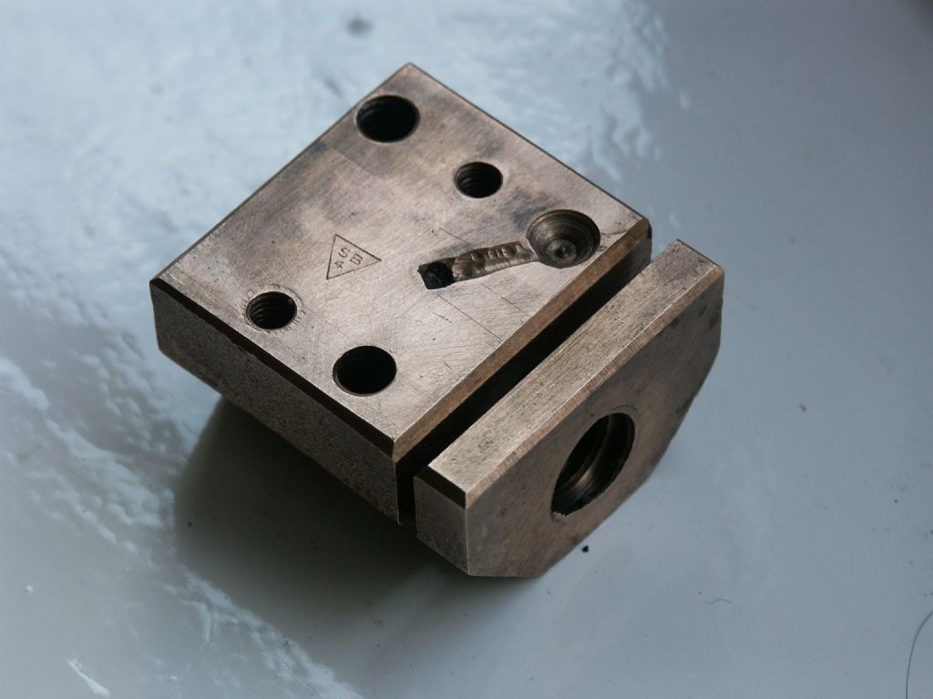
I'm in the position of having to make a replacement nut for the cross slide on my Smart & Brown lathe. I am puzzled as to the purpose of the slit at one end that penetrates halfway across the thread.
Any ideas?
 Regards Brian G3oyu. |
| Keith Long | 06/03/2010 13:05:06 |
| 883 forum posts 11 photos | Hi If you mean the full width slot at 90 deg to the thread axis - is there any provision for applying pressure the the "unsupported" bit to close it up and adjust the backlash - or possibly to insert a backlash "eliminator"? For the angled short slot - a lubrication path maybe? Keith |
| Jeff Dayman | 06/03/2010 13:46:57 |
| 2356 forum posts 47 photos | I'm not sure, but this may be a passive backlash eliminator. the thin end after cutting at the factory could have been given a press or bash to slightly deform it toward the main part of the nut. This would result in a very slight deformation of the thread pitch. When assembled to the leadscrew the thin end would spring back to conform with the thread pitch, but the interference force would take up some backlash. This would be rather rough on the leadscrew, but maybe they used a hardened leadscrew.
On other antilbacklash systems in different machines separate springs and other devices do the same thing.
The angled slot on top is an oilway as Keith mentioned. |
| Brian Davies | 06/03/2010 16:27:41 |
| 27 forum posts 1 photos | Thank you all for your suggestions, it is much as I thought. No there is no means of applying pressure to the thin end of the slot once the nut and screw are assembled into the cross slide. I think the suggestion that a good wack with a hammer to slightly deform the nut prior to assembly is the correct one.
Regards
Brian |
| Keith Long | 06/03/2010 16:40:39 |
| 883 forum posts 11 photos | If you're making a new nut, is there room to drill and tap 1 or 2 holes parallel to the main screw axis, say 45 degrees up either side form the screw, and insert some smallish machine screw ,csk heads probably, so you can put a bit of squeeze or spread on the bit that's partially split off to give yourself some backlash adjustment. Another thought if you're copying the split as well is to make a loose piece that goes in there with a shim to pack it to the size of the slit, and again hold it in place with some small csk screws. Cut the thread in the nut, including the loose piece, then by adjusting the shims you can move the loose piece to and fro in the slit and alter the backlash that way - possibly? Keith |
| Steve Garnett | 06/03/2010 20:26:27 |
| 837 forum posts 27 photos | I'm intrigued now. Which Smart and Brown is it? On our 1024, the cross-slide backlash is adjustable, and I find it difficult to believe that a firm who produced what is quite a good toolroom lathe with the correct means of adjustment would resort to a 'bash it' solution on another one... |
| Brian Davies | 07/03/2010 07:42:46 |
| 27 forum posts 1 photos | Hi
Many thanks for the reply and thoughts. I too have doubts about S&M making something that needed a wack to set it up! My machine is a Model A and is otherwise a fine machine. It already performs well on brass and free cutting mild steel. The problem became apparent when I tried machining silver steel, because it is rather tough the cross slide clearly started to move around on the backlash.
I am looking at modifying the new nut to incorporate some backlash adjustment but just how to do this satisfactorily has yet to be decided. Something similar to your suggestion Keith seems a good possibility.
The other thought is to provide a way to lock the cross slide so that it cannot move when traversing along the bed.
Brian |
| Steve Garnett | 07/03/2010 12:50:11 |
| 837 forum posts 27 photos | The Model A cross-slide looks similar to the 1024 one, but the only cutaway diagram of it I could find shows that it is significantly different underneath, although there is no detail shown of the nut itself - just a solid block. If I recall correctly (it's a long time since I had it to bits), the 1024 adjustment consists of an extra bit of tapped nut on the end of the nut proper, and it has two radial slots in it so that it can be turned, and then locked in place with a couple of cap head screws. So in theory you could turn rotate it up to the point where the threads bound if you wanted, although ours never quite did that, even right at the end of the slot travel. The other thing about it that I seem to recall is that the extra bit of nut isn't made of steel, although I'd really have to check that to be sure of what it is. We manage to turn small grooves in stainless tube with the 1024 without too much of a problem, as long as you do it all in one hit, and it doesn't really give any grief at all once you have the technique sorted. |
| Brian Davies | 07/03/2010 15:14:06 |
| 27 forum posts 1 photos | Thanks for the comments Steve. I've been doing some further research this morning and find that beneath some crud there is a socket head grub screw, in the top of the cross slide, with a cone shape at the bottom that when screwed in does in fact act on the slit thereby opening it out. This will take up some backlash but how much I don't know.
So no 'bash' with a heavy hammer needed!
I am rather confused about the leadscrew dimensions however. This measures up at exactly 1/2 inch diameter and 8TPI. Reading Advanced Machine Work it seems that for 1/2 inch the TPI should be 10. I'm sure it doesn't matter what the TPI is providing it matches the leadscrew.
Fortunately the book goes into the thread shape in great detail as well as the correct shape to grind the cutting tool too.
I have an enquiry out for a suitable lump af phosphor bronze and once I have that I will be able to make the replacement. However I am going to look at the possibility of creating a modified backlash eliminator (I don't trust my machining too much!)
Brian |
| Steve Garnett | 08/03/2010 00:23:39 |
| 837 forum posts 27 photos | I'm not at all convinced there's any absolute standard at all when it comes to leadscrews; diameters, thread pitches or even the thread profile can vary according to manufacturers' whims, and also according to whether you have a metric one or not. Okay, that seems to be a bit unlikely on a model A... As you say, having the correct pitch for the nut, regardless of what it actually is, is rather more important! As far as the thread itself is concerned, you should check carefully that the thread shape/profile given in that lovely old American publication (that can now be downloaded for free, along with the companion 'Elements' book) is actually the same as the UK-manufactured leadscrew's is; I wouldn't put it past a UK manufacturer to adopt a slightly different profile as well as 'non-standard' TPI! |
| Brian Davies | 08/03/2010 07:42:52 |
| 27 forum posts 1 photos | Thanks for that Steve, I will take care to get the profile as accurate as I can. I do have a shadow graph machine that at present is not working. It will pay me to sort this out and then I can take profile off the leadscrew and be certain that it is right.
Brian |
| Steve Garnett | 09/03/2010 03:13:48 |
| 837 forum posts 27 photos | Turns out that my memory of the cross-slide backlash adjuster wasn't quite correct. The one I described is how it works on the top slide, not the cross slide. But since the cross slide one is slightly more interesting, I did a very quick drawing of it, just so you get the idea. This isn't my idea of a good machine drawing, incidentally - just quick and dirty to show the principle, and with all sorts of things like bolts left out (the bit on the right that I forgot to label and is irrelevant anyway is the oiler hole): 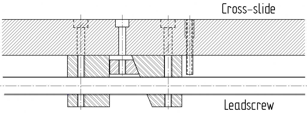 |
| Steve Garnett | 09/03/2010 10:37:53 |
| 837 forum posts 27 photos | What I forgot to add was that I much prefer this version of a backlash eliminator to the one that distorts the nut, simply because there is an even axial force on the leadscrew, rather than a potentially distorting one that will cause uneven thread wear in the long run. I don't know about you, Brian, but if I was going to fabricate a new nut, I would have thought that a version like this would not be too difficult at all to make. Looking back through the thread, it would appear that doing it this way is very similar to Keith Long's suggestion - only adjustable in situ - always an advantage! |
| Brian Davies | 18/03/2010 08:40:01 |
| 27 forum posts 1 photos | Many thanks for all the replies, I'm sorry I was unable to reply sooner but last Monday week I was rushed into hospital with a suspected heart attack. As it has turned out it wasn't one but the test done have thrown up a problem that will need sorting. I managed to escape yesterday and am only now managing to work through several hundred emails!
I now have a lot of information about cross slide nuts and will digest this in due course and once my problem is solved and I'm back in the workshop I'll make a decision on how to proceed.
Kind regards
Brian G3OYU |
| Steve Garnett | 19/03/2010 00:13:54 |
| 837 forum posts 27 photos | Best wishes for a speedy full recovery, Brian. |
| Brian Davies | 19/03/2010 09:34:24 |
| 27 forum posts 1 photos | Many thanks for that Steve.
Brian |
| Richard Shute | 31/03/2010 00:15:34 |
| 7 forum posts | Good evening all, I'm new here, but a regular on various other fora. I was prompted to respond as I have, some Smart & Brown lathes and a fairly intimate experience of messing about with them. Firstly you may like to consider the Yahoo Smart & Brown group dedicated to these lathes. It is friendly and active and an Operators Manual and Parts Lists are available for free download once you have subscribed, although the details of the feedscrew nut are not very explicit. You might also consider talking to Bracehand Ltd near Hitchin (Google it), Chris, the proprietor, was an employee of S&B's and he bought the S&B name and remaining spares and all their old drawings when they went under. It is not inconceivable he may have a new or 'good used' nut and/or feedscrew. Brian, you have correctly deduced the backlash adjustment on the Mdl A, the taper tipped screw opens the split to reduce the clearance. Make sure that you adjust the nut on an unworn part of the screw or it will bind when you do move to an unworn area. It is probable that most of the backlash can be adjusted out, but any remaining will be due to wear in the scew, not the nut. This will manifest itself as a variation in the backlash over the range of movement. If this is unacceptable, it is the screw more than the nut that needs replacement. You are pretty much committed to the 8 TPI when you consider the 0~125 graduations on the handwheel. It has caught me out and my chum who's Mdl A I serviced last year, but unless you change the handwheel as well you are in for some major confusion! The two part nut that Steve described is used in the top compound slide of both the Mdl A and 1024 as well as some of their other machines. I agree that I prefer either of the two part nut arrangements to the tortured nut on the MdlA, but the original has lasted 60 odd years so it can't be too bad. Backlash would not normally give rise to the carriage floating about in use, have you checked the gibb strips for correct adjustment? It might be worth a look. Rgds Richard |
| Brian Davies | 31/03/2010 09:18:27 |
| 27 forum posts 1 photos | Hi Richard
Many thanks for the info, I have applied to join the S&M group on Yahoo. I already have a copy of the manual, coutesy of Tony at Lathes.co.uk.
I will certain call Bracehand today and see what they may have available.
The existing gib strip adjusting screws leave a lot to be desired and I am in the process of considering how to improve them. What I would like to do is replace them with suitably long socket head grub screws but to date I have been unable to find any long enough.
One thing the service manual does not say is the correct proceedure to adjust the gib strip and I'm not sure of the way to do this to realize the best end result. Perhaps others on this forum could advise me?
Kind regards
Brian |
| Richard Shute | 31/03/2010 10:54:29 |
| 7 forum posts | Posted by Brian Davies on 31/03/2010 09:18:27:
<...>
One thing the service manual does not say is the correct proceedure to adjust the gib strip and I'm not sure of the way to do this to realize the best end result. Perhaps others on this forum could advise me?
Kind regards
Brian
Brian, |
| Brian Davies | 31/03/2010 11:23:17 |
| 27 forum posts 1 photos | Richard
Many thanks for that, yes the locking ring is a pain I had already decided to knock up a hollow driver to deal with the ring, your suggestion looks good and of course it can be hardened and tempered afterwards.
I've been onto Bracehand and they are going to get back to me.
Regards
Brian |
Please login to post a reply.
Magazine Locator
Want the latest issue of Model Engineer or Model Engineers' Workshop? Use our magazine locator links to find your nearest stockist!
Sign up to our Newsletter
Sign up to our newsletter and get a free digital issue.
You can unsubscribe at anytime. View our privacy policy at www.mortons.co.uk/privacy
Latest Forum Posts
- *Oct 2023: FORUM MIGRATION TIMELINE*
05/10/2023 07:57:11 - Making ER11 collet chuck
05/10/2023 07:56:24 - What did you do today? 2023
05/10/2023 07:25:01 - Orrery
05/10/2023 06:00:41 - Wera hand-tools
05/10/2023 05:47:07 - New member
05/10/2023 04:40:11 - Problems with external pot on at1 vfd
05/10/2023 00:06:32 - Drain plug
04/10/2023 23:36:17 - digi phase converter for 10 machines.....
04/10/2023 23:13:48 - Winter Storage Of Locomotives
04/10/2023 21:02:11 - More Latest Posts...
- View All Topics
Support Our Partners


Shopping Partners
Subscription Offer

Latest "For Sale" Ads
- Reeves** - Rebuilt Royal Scot by Martin Evans
by John Broughton
£300.00 - BRITANNIA 5" GAUGE James Perrier
by Jon Seabright 1
£2,500.00 - Drill Grinder - for restoration
by Nigel Graham 2
£0.00 - WARCO WM18 MILLING MACHINE
by Alex Chudley
£1,200.00 - MYFORD SUPER 7 LATHE
by Alex Chudley
£2,000.00 - More "For Sale" Ads...
Latest "Wanted" Ads
- D1-3 backplate
by Michael Horley
Price Not Specified - fixed steady for a Colchester bantam mark1 800
by George Jervis
Price Not Specified - lbsc pansy
by JACK SIDEBOTHAM
Price Not Specified - Pratt Burnerd multifit chuck key.
by Tim Riome
Price Not Specified - BANDSAW BLADE WELDER
by HUGH
Price Not Specified - More "Wanted" Ads...
Get In Touch!
Do you want to contact the Model Engineer and Model Engineers' Workshop team?
You can contact us by phone, mail or email about the magazines including becoming a contributor, submitting reader's letters or making queries about articles. You can also get in touch about this website, advertising or other general issues.
Click THIS LINK for full contact details.
For subscription issues please see THIS LINK.
Digital Back Issues


Donate

 Register
 Log-in
Model Engineer Magazine
- Percival Marshall
- M.E. History
- LittleLEC
- M.E. Clock

ME Workshop
- An Adcock
- & Shipley
- Horizontal
- Mill

Subscribe Now
- Great savings
- Delivered to your door

Pre-order your copy!
- Delivered to your doorstep!
- Free UK delivery!
All Forum Topics > General Questions > Smart & Brown Nut