Forum sponsored by:

Diamond shaped steam piston glands/pipe glands
Making them without a rotary table
| Ramon Wilson | 17/06/2022 23:09:12 |
 1655 forum posts 617 photos | In the thread by Dr G on his making of the Stuart Twin Victoria the making of these small but significant parts has been discussed. Rather than spoil Doc's thread here are a few images to explain an alternative way of manufacture. First off some simple maths to establish the half angle of the diamond is required. Once this is known the 'fixture' can be tackled. It's just a simple piece of mild steel plate (ali would do) with two parallel edges a bit wider that the mill vise depth.This has a hole drilled in close to the edge that will take the diameter of the gland boss. Another hole is drilled to coincide with the gland bolt hole at the angle previously worked out The plate with two embryo glands. The deep chamfer is to cater for the radius on the boss
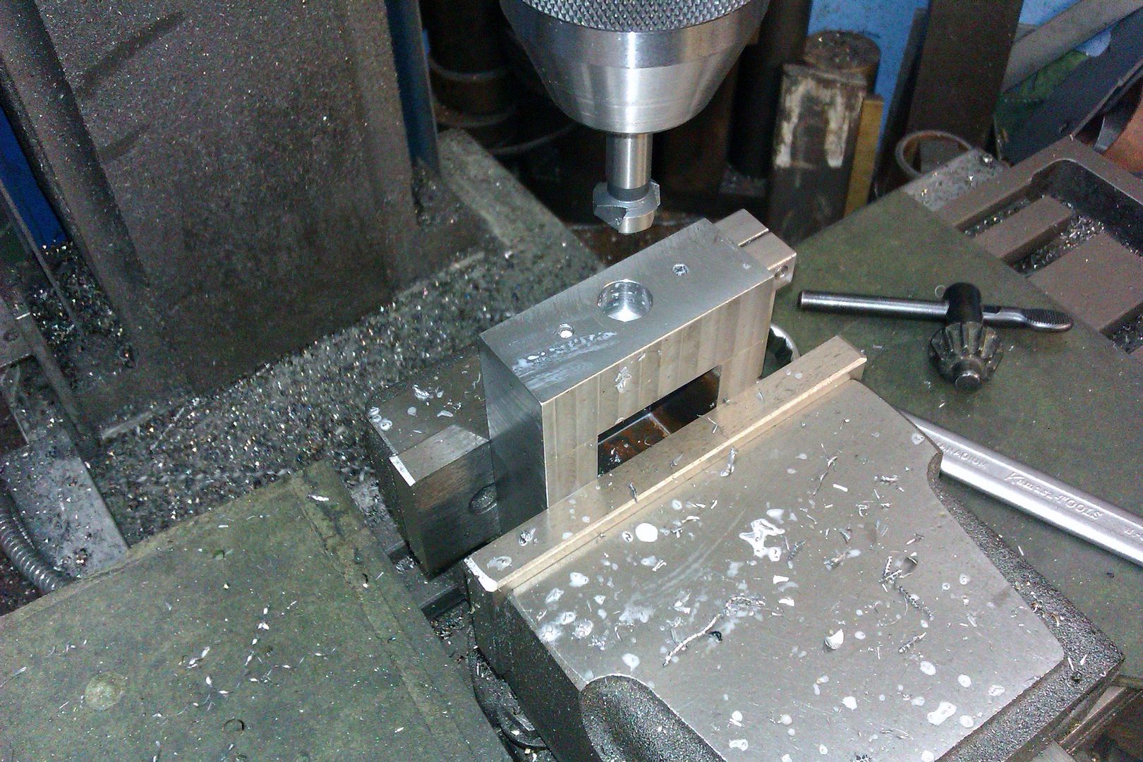
The plate is set level in the vise (image gives the appearance of an angle but it is parallel with the table) and the cutter set to the depth required.
A small pin is turned to match the clearance hole and the boss clamped in place. The part is milled to the depth set........
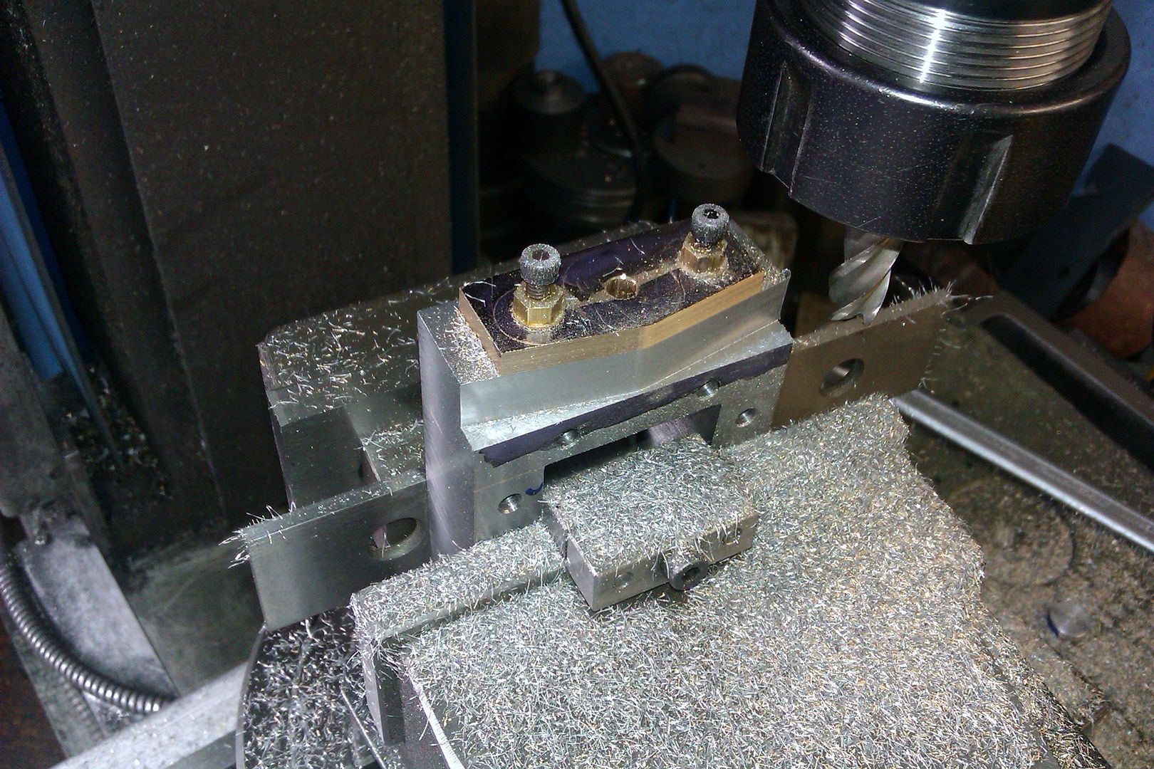
.........then rotated to mill the opposite side
The plate can then be reversed or the part inserted from the other side of the plate to do the same on the remaining edges
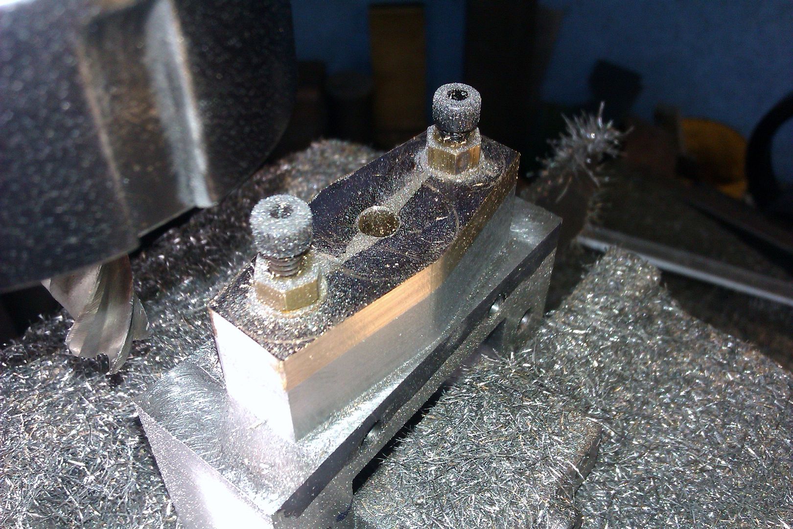
Initial milling complete
A filling button is turned up and hardened.....
.......and the ends brought to shape by filing
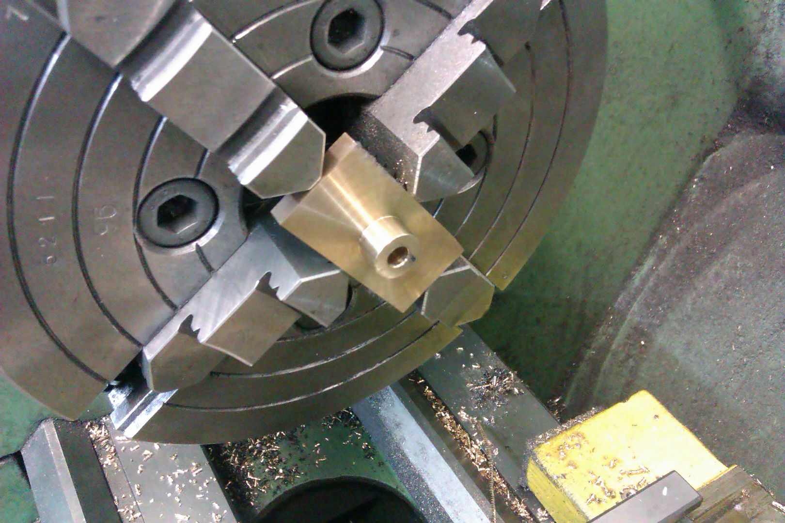
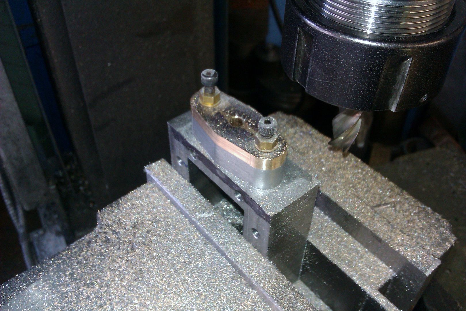
I appreciate this shows steam pipe glands but the principle is exactly the same for piston rod glands. The part would not have a centre hole in at this stage however. It would then be bolted to it's respective cylinder cover and be drilled and reamed together This image shows a round gland being opened up with an FC3 cutter before being drilled and reamed in such an operation
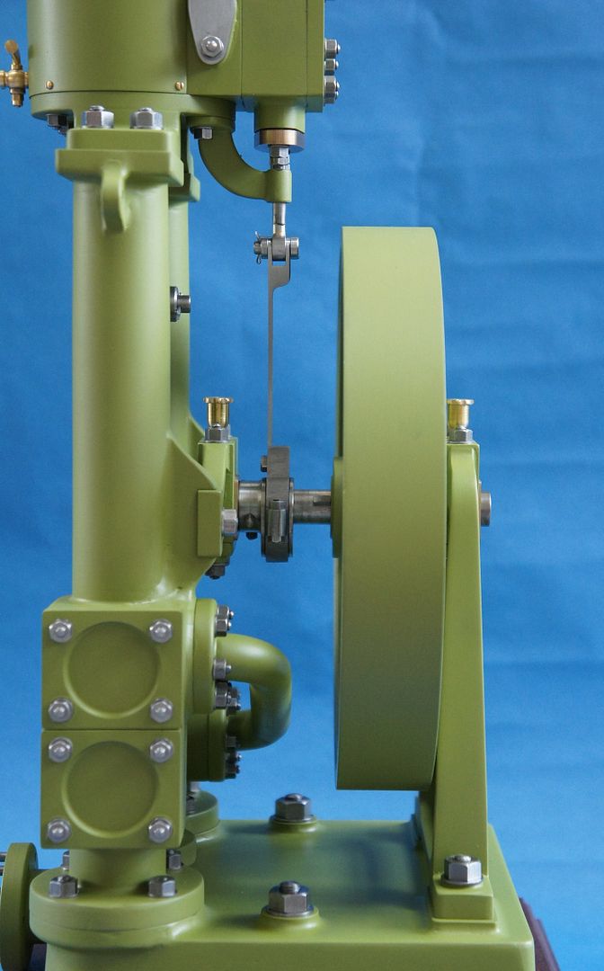
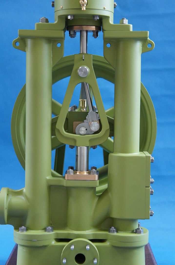
Here is a pic of my Twin Vic which is when I came up with the above method - have used it many times since
Hope that's of interest to you and to anyone else that it can benefit Ramon (Tug)
|
| Jeff Dayman | 18/06/2022 01:07:57 |
| 2356 forum posts 47 photos | Great to see your thread Tug! fine work on your twin Victoria. Hope things are going great with you. Cheers! |
| Hopper | 18/06/2022 01:18:35 |
 7881 forum posts 397 photos | I have done the same job by using 3 pairs of steel filing buttons. One large in the middle and one small each side, held in place with small screws and nuts. I dont bother to harden the buttons for a one off job on brass. I did have to file flats on the buttons to get them so close together. One of those jobs where it takes longer to make the buttons than to file the actual part. My engine building standards are certainly not up to yours but it "does a turn" as my old man always said.
Edited By Hopper on 18/06/2022 01:21:32 |
| JasonB | 18/06/2022 07:24:13 |
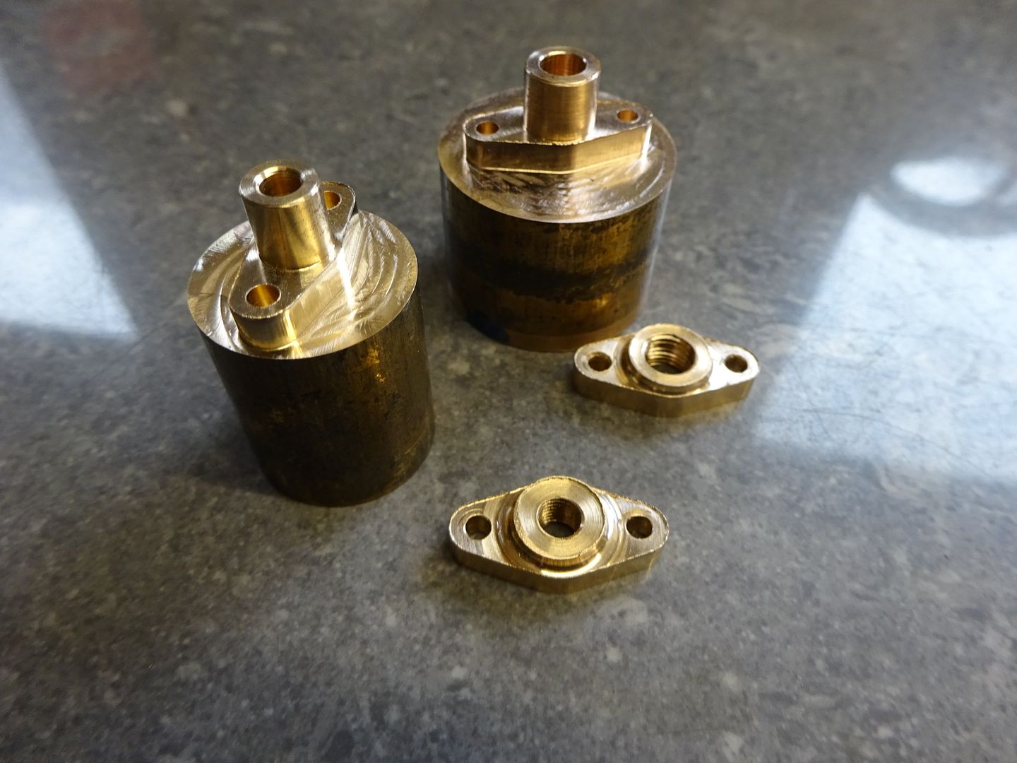
 25215 forum posts 3105 photos 1 articles | I have a different approach which was probably developed as I often also need to shape the matching boss that the gland fits into. It also works on poorly shaped castings that need the boss cleaning up. First the "Casting" is drilled, tapped, reamed and counter bored so that the embryo gland can be screwed on and the two machined as one.
Then the boss on the gland is turned and the hole reamed, her eI'm using a piece of bar a sit's quite a large gland, smaller would just be turned on the end of round bar before parting/sawing off and cleaning cp the top with a skim cut.
After drilling the stud holes in the gland it can be screwd in place. Then set up the rotary table and a means of holding the assembly which will usually be the vice (clocked in on X) and get the rod hole true under the spindle, zero DRO or handwheels and note R/T angle if not zero. Now the shape can start to be milled out. Turn the rotary table to the first flank angle and rough that out leaving 0.25mm and then repeat for the other three flank angles. You can then go back to do a final pass which is done as a flank angle then with out moving the cutter rotate the table so it forms the mid radius and then when you get to the opposite angle lock the table and carrying with the straight cut out to the end, repeat on the opposite end. All this can be done with full depth cuts ratherthan wear out just the end of the cutter
Here is a close up of the basic diamond with a smooth transition from flat to round and to flat again
To round the ends put your vice stop in place with a bit of packing (don't have any gauge blocks) between that and the part which is the size of the stud offset. Remove the packer and slide the part up against the stop. The spindle will now be directly above one of the stud holes so a simple job to offset by the required radius plus half cutter diameter and round off an end, repeat for the other either by flipping the work in the vice if the boss is central in Y or moving to the opposite side of the vice if offset such as you find on the Stuart Victoria valve gland
Bit of paint and jobs done, also used this method for the piston rod gland
Edited By JasonB on 18/06/2022 07:24:57 |
| JasonB | 18/06/2022 07:32:30 |
25215 forum posts 3105 photos 1 articles | These days I am likely to take a different approach and use the best tool for the job though not everyone has a CNC in the shed.. My CAM program tells me that each gland on the left tool 1min 35 sec to profile the diamond, the spigot having been previously turned on the bar. A further 13 seconds to add the two stud holes. Each is shaped differently to suit the cast boss. The two castings for the pipes also had their external shape done on the same tool, 21secs each.
The same tool can also do a batch of glands complete with draft angle that can be used as a pattern for casting
Edited By JasonB on 18/06/2022 07:37:07 |
| Ramon Wilson | 18/06/2022 08:24:33 |
1655 forum posts 617 photos | Ah, but the difference is Jason, a simple piece of steel plate or CNC - depends what's available to most eh Love that green BTW Jeff, apart from an oscillator that Twin Vic was my first steam engine built sometime in the eighties I think. I sold it via 'Old Glory' mag quite some time ago to a lovely old boy who obviously was going to appreciate it. I expect he's gone know - wonder what happened to it? As always Hopper there are many ways of skinning that cat usually all born from trying to simplify matters without losing the precision.
Best - Tug
|
| Hopper | 18/06/2022 09:17:47 |
7881 forum posts 397 photos | Yes I am just lazy and use soft mild steel buttons and file down to them carefully. Works ok with steel buttons on a brass job but for steel jobs I do prefer hardened silver steel buttons too. I must get me a milling machine one of these days and do this stuff the easy way! |
| Tomfilery | 18/06/2022 09:34:23 |
| 144 forum posts 4 photos | Gentlemen, Thank you for a nice instructive thread. Ideas to be "parked" for when the job requires it, methinks! I'd like to ask Jason a question re the first picture in his post of 07:32:30 today - how do you cut the almost finished glands from the round stock? A slitting saw, or something else fiendishly clever? Regards Tom |
| JasonB | 18/06/2022 10:10:37 |
25215 forum posts 3105 photos 1 articles | I just lopped them off with a hacksaw, parting would be another option. Then held in a collet by the spigot to tidy up the saw cut. It would have been possible to do it all on the CNC in which case some form of saw to remove the part would be an option, certainly is on commercial machines. If you watch this video from about 6mins in which is where it should start you can see he first chamfers where the cut will be then uses a saw to cut the parts off all but a wafer thin strip to stop them flying into the swarf. Edited By JasonB on 18/06/2022 10:13:26 |
| Tomfilery | 18/06/2022 19:56:28 |
| 144 forum posts 4 photos | Jason, Nice to see how the professional does it (in the video). Many thanks. Regards Tom |
.jpg")
.jpg")
.jpg")
.jpg")
.jpg")
.jpg")
.jpg")
.jpg")
.jpg")
.jpg")


Please login to post a reply.
Magazine Locator
Want the latest issue of Model Engineer or Model Engineers' Workshop? Use our magazine locator links to find your nearest stockist!
Sign up to our Newsletter
Sign up to our newsletter and get a free digital issue.
You can unsubscribe at anytime. View our privacy policy at www.mortons.co.uk/privacy
Latest Forum Posts
- *Oct 2023: FORUM MIGRATION TIMELINE*
05/10/2023 07:57:11 - Making ER11 collet chuck
05/10/2023 07:56:24 - What did you do today? 2023
05/10/2023 07:25:01 - Orrery
05/10/2023 06:00:41 - Wera hand-tools
05/10/2023 05:47:07 - New member
05/10/2023 04:40:11 - Problems with external pot on at1 vfd
05/10/2023 00:06:32 - Drain plug
04/10/2023 23:36:17 - digi phase converter for 10 machines.....
04/10/2023 23:13:48 - Winter Storage Of Locomotives
04/10/2023 21:02:11 - More Latest Posts...
- View All Topics
Support Our Partners


Shopping Partners
Subscription Offer

Latest "For Sale" Ads
- Reeves** - Rebuilt Royal Scot by Martin Evans
by John Broughton
£300.00 - BRITANNIA 5" GAUGE James Perrier
by Jon Seabright 1
£2,500.00 - Drill Grinder - for restoration
by Nigel Graham 2
£0.00 - WARCO WM18 MILLING MACHINE
by Alex Chudley
£1,200.00 - MYFORD SUPER 7 LATHE
by Alex Chudley
£2,000.00 - More "For Sale" Ads...
Latest "Wanted" Ads
- D1-3 backplate
by Michael Horley
Price Not Specified - fixed steady for a Colchester bantam mark1 800
by George Jervis
Price Not Specified - lbsc pansy
by JACK SIDEBOTHAM
Price Not Specified - Pratt Burnerd multifit chuck key.
by Tim Riome
Price Not Specified - BANDSAW BLADE WELDER
by HUGH
Price Not Specified - More "Wanted" Ads...
Get In Touch!
Do you want to contact the Model Engineer and Model Engineers' Workshop team?
You can contact us by phone, mail or email about the magazines including becoming a contributor, submitting reader's letters or making queries about articles. You can also get in touch about this website, advertising or other general issues.
Click THIS LINK for full contact details.
For subscription issues please see THIS LINK.
Digital Back Issues


Donate

 Register
 Log-in
Model Engineer Magazine
- Percival Marshall
- M.E. History
- LittleLEC
- M.E. Clock

ME Workshop
- An Adcock
- & Shipley
- Horizontal
- Mill

Subscribe Now
- Great savings
- Delivered to your door

Pre-order your copy!
- Delivered to your doorstep!
- Free UK delivery!
All Forum Topics > Hints And Tips for model engineers > Diamond shaped steam piston glands/pipe glands