Forum sponsored by:

Treadmill Motor & Control Housings
500W 220V DC Treadmill Motor kit
| Chris V | 07/11/2020 17:01:53 |
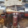 313 forum posts 42 photos | I bought a treadmill motor and controller to power a die filer. The die filer is c1910 vintage and I wish to build a housing for both motor and controller. 50/50 to keep the filings out / to hide them as far as possible. It will be on a movable baseboard to sit on my workbench, the motor cannot go underneath The motor itself is open each end ie likely needs some ventilation. The control box as you can see in the photo has a perforated casing suggesting this too needs some airflow around it. A visiting electritan suggested 1/2" or so gap around the controller would be fine, but as I have no idea I'm asking the question, how much space between the components and any housings should I allow? Thanks Chris.
|
| Chris V | 09/11/2020 16:04:01 |
313 forum posts 42 photos | Any thoughts on this one please? Chris. |
| IanT | 09/11/2020 16:58:58 |
| 2147 forum posts 222 photos | I think you've already answered your question Chris. It sounds like a simple box at the rear of the base will do the business. You will need to bring the shaft out to one side to drive the filer and make a hole for the speed control. Bring the power lead out the back and make sure it's well anchored. You could make the box out of sheet metal but I find 6mm ply is very convenient for this kind of thing. If you think ventilation is an issue, make some slots in the back. Make the box large enough to take the parts and to look like it was designed (rather than just knocked together) and I'm sure it will be fine. I've just converted my 1/4" Cowells drill to DC drive. I needed to mount the motor and after faffing around with various bits of angle iron, finally just made an open box to hold the motor and give some adjustment for belt tension. The PSU (which sits behind the drill pillar) came in a somewhat flimsy plastic case, so a ply cover will be used to keep out wandering swarf. The motor didn't have 'feet' as such, so I printed a 3D saddle to hold it (designed in Open SCAD). It's all painted etc now and looks fairly neat and seems to work - I've still some things to tidy up. Here is the open ply 'box' before painting etc. A 2x4ft sheet of 6mm ply is not expensive and can be used for all sorts of jobs like this. The slots were drilled at each end and then just cut with a jig saw. Try it and if you have problems, then change or improve it - it will probably be fine but maybe not. Either way you will learn what is required in practice, without breaking the bank or spending loads of time on an overkill. Regards, IanT
Edited By IanT on 09/11/2020 17:03:23 |
| Chris V | 09/11/2020 19:05:43 |
313 forum posts 42 photos | Thank you Ian, some good pointers there that are most helpful and I will take onboard. How do you find the motor, are you pleased with it? Chris. |
| IanT | 09/11/2020 20:18:00 |
| 2147 forum posts 222 photos | Hi Chris, Yes, it's a nominal 200W DC but I suspect it actually delivers a bit less than that. It also has a 'remote' control which I'm going to try for a while but I might substitute for my own-brew IR/PWM controller if it doesn't work out. So I now have variable speed on all three pulleys, so that's an improvement. It works very well on smaller drill bits 1-2mm (which is what it's going to be mainly used for) but I was getting belt slip on a 6mm one. I need to alter the 'V' depth on the motor pulley I'm using to match the belt but it was OK for a quick test. So the motor seems to have sufficient welly for its intended use. I have a large (12-speed) drill press as well as the usual Dremel, Proxxon etc tools that most modellers have, so I've got plenty of choice. Regards, IanT
|
| IanT | 09/11/2020 20:48:35 |
| 2147 forum posts 222 photos | PS - It kind of looks like this - the (much larger) motor was sat behind the drill previously with the belt running up and over jockey pulleys. This arrangement seems neater and the belt is quieter. I use both the original drill table and the compound vice (which can just be lifted off). I've fitted extra bearings and reversed the 'Y' handle to make it a bit easier to use. It's not intended to be an accurate X/Y table - but it is a convenient way to set up smaller work. I decided to change my 'control' box around a bit - the first one was a bit too high. Regards, IanT PS Mods - Can you rotate images??
|
| Chris V | 10/11/2020 09:57:57 |
313 forum posts 42 photos | Thanks for all this Ian. Not knowing anything about motors and bearing in mind it was both cheap and modern made I had my reservations as to whether 200w would be powerful enough, so went for a 500w version. Time will tell if that was overkill, but I'd rather have too much power for the filer than not enough. I'm still using a small grinder and belt sander I bought 30 years ago, both of which whilst still hanging in there are under powered and so a constant source of frustration. Your drill/motor set up looks neat, I have a UPT and Champion No 1 that also need motors. I found on eBay a modern replacement motor for a Unimat with inbuilt variable speed which is very neat and compact that I will in time fit to the UPT. Today I need to study the Polly Vee pulley on my treadmill motor, I want to replace it with an iron or brass one, thinking maybe (I'm a beginner) I can turn one, just concerned about getting the regularly spaced vee grooves correct. Before that though I shall mostly be learning to use a 4 jaw. Chris. |


Please login to post a reply.
Magazine Locator
Want the latest issue of Model Engineer or Model Engineers' Workshop? Use our magazine locator links to find your nearest stockist!
Sign up to our Newsletter
Sign up to our newsletter and get a free digital issue.
You can unsubscribe at anytime. View our privacy policy at www.mortons.co.uk/privacy
Latest Forum Posts
- *Oct 2023: FORUM MIGRATION TIMELINE*
05/10/2023 07:57:11 - Making ER11 collet chuck
05/10/2023 07:56:24 - What did you do today? 2023
05/10/2023 07:25:01 - Orrery
05/10/2023 06:00:41 - Wera hand-tools
05/10/2023 05:47:07 - New member
05/10/2023 04:40:11 - Problems with external pot on at1 vfd
05/10/2023 00:06:32 - Drain plug
04/10/2023 23:36:17 - digi phase converter for 10 machines.....
04/10/2023 23:13:48 - Winter Storage Of Locomotives
04/10/2023 21:02:11 - More Latest Posts...
- View All Topics
Support Our Partners


Shopping Partners
Subscription Offer

Latest "For Sale" Ads
- Reeves** - Rebuilt Royal Scot by Martin Evans
by John Broughton
£300.00 - BRITANNIA 5" GAUGE James Perrier
by Jon Seabright 1
£2,500.00 - Drill Grinder - for restoration
by Nigel Graham 2
£0.00 - WARCO WM18 MILLING MACHINE
by Alex Chudley
£1,200.00 - MYFORD SUPER 7 LATHE
by Alex Chudley
£2,000.00 - More "For Sale" Ads...
Latest "Wanted" Ads
- D1-3 backplate
by Michael Horley
Price Not Specified - fixed steady for a Colchester bantam mark1 800
by George Jervis
Price Not Specified - lbsc pansy
by JACK SIDEBOTHAM
Price Not Specified - Pratt Burnerd multifit chuck key.
by Tim Riome
Price Not Specified - BANDSAW BLADE WELDER
by HUGH
Price Not Specified - More "Wanted" Ads...
Get In Touch!
Do you want to contact the Model Engineer and Model Engineers' Workshop team?
You can contact us by phone, mail or email about the magazines including becoming a contributor, submitting reader's letters or making queries about articles. You can also get in touch about this website, advertising or other general issues.
Click THIS LINK for full contact details.
For subscription issues please see THIS LINK.
Digital Back Issues


Donate

 Register
 Log-in
Model Engineer Magazine
- Percival Marshall
- M.E. History
- LittleLEC
- M.E. Clock

ME Workshop
- An Adcock
- & Shipley
- Horizontal
- Mill

Subscribe Now
- Great savings
- Delivered to your door

Pre-order your copy!
- Delivered to your doorstep!
- Free UK delivery!
All Forum Topics > General Questions > Treadmill Motor & Control Housings