Forum sponsored by:

VFD. XSY AT4 220v 1phase to 380v 3phase advice sort
| Andrew Firman | 23/05/2020 13:32:14 |
| 37 forum posts 18 photos | I have a couple of 2.2Kw XSY AT4 which I want to use to power a couple of 380V 3 phase star wired motors using 220v single phase supply. I've bench run a 1/2hp motor successfully using the key panel for control but have run into a problem when trying to control speed using a 10K pot. For some reason I'm only able to obtain exactly half the max hz set in the vfd that I was able to achieve with the keyboard. I'm hoping someone will be able to advise why this might be the case and how I can get the full hz range using the Pot. Unlike the other ATs in the series the AT4 1: has no earth terminal . I was planning to earth the cooling fins but measured 85v ac between the fins and supply earth. Is this to be expected? Should I earth it?
2: has only 1 COM terminal on the control ports. The voltage between this COM and the 5v/10v terminal measures 5v Could this be causing the half max hz with the Pot?
The manual that came with the vfds is the same AT series manual that other people have posted for the AT1 Thanks in anticipation. |
| Clive Foster | 23/05/2020 14:21:58 |
| 3630 forum posts 128 photos | Andrew I'd always understood that half speed running was normal if trying to run a star connected (400 v) motor off a 220 v inverter. As per this link **LINK** . Its possible that the internal parameter settings will allow the keypad to do things the control pot can't. I've encountered that before on another breed where the pot wouldn't run the motor up past 60 Hz yet the keypad would quite happily go much faster. Clive |
| Andrew Firman | 23/05/2020 14:50:54 |
| 37 forum posts 18 photos | Clive, Thanks for response. I believe this vfd is supposed to be a “step up” vfd ie the output is 380v 3 phase at 50hz. I’ve used a true rms meter to confirm that this is in fact the case. The vfd is marketed as such too. I guess I could increase the max operating hz parameter to say 140hz. Then using the pot would give me a max hz of 70 hz. Do you have any thoughts on the lack of protection earth and the measured 85v ac between supply earth and the cooling fins? |
| SillyOldDuffer | 23/05/2020 15:03:03 |
| 10668 forum posts 2415 photos | Had a look at the Manual and it says the voltage is 5/10V. And then silence - very unhelpful! It implies to me the reference voltage can be either 5V or 10V, therefore I'd expect a physical switch or parameter setting allowing it to be changed. And it sort of follows that a pot connected to 5V when VC1 expects up to 10V will only be able to run the motor up to half speed.
Should be possible to prove whether or not it's lack of 10V causing the problem by substituting a 9V battery for the 5V terminal. (Connect - to COM and + to top of pot.) Wind the motor up gently from 0V on VC1 : if it keeps speeding up when the pot goes past half way, it strongly suggests 10V is needed. If the motor doesn't go faster beyond the pot's half way setting, don't push on regardless up to 9V in case it damages the input electronics. I don't know if its OK or not for the fins to be at 85V on an AT4. Probably OK because lots of power electronics are cooled that way. Heatsinks can be earthed or floating. The unit is meant to be operated inside a box, usually steel, and it's the user facing box that's earthed, not the VFD. If a unit doesn't come with an earth terminal, don't make one up! With luck an AT4 owner will be along who will explain all. Why is nothing ever easy? Dave
|
| Andrew Johnston | 23/05/2020 15:09:44 |
 7061 forum posts 719 photos | The linked article has been discussed before; when I blew a rather large raspberry about it. After some discussion I think we decided that what he's actually doing is reducing the base speed of a star connected motor running from a 240V output inverter in order to maximise the constant power part of the curve. So I'd now blow half a raspberry. The speed of an induction motor is primarily determined by the applied frequency. Voltage doesn't come into it. For any given motor at a given frerquency the voltage will determine the phase currents which in turn determine the torque. I suspect the described problem is to do with internal parameters and/or the wiring of the pot not giving the voltages expected. On the VFD that I happen to have sitting on the bench the heatsink has screws in two corners and the case has two moulded earth symbols next to the screws. That implies that the semiconductors on the heatsink are electrically isolated from the heatsink and the heatsink can be earthed. That may not be the case for cheap VFDs. If there isn't a terminal somewhere explicitly marked as earth I'd immediately bury the unit in the earth and forget about it. Andrew |
| Andrew Firman | 23/05/2020 16:14:02 |
| 37 forum posts 18 photos | Thanks Dave, I have a steel enclosure which I’m going to mount the vfd in. I’m hoping Martin of Wick responds because I’m sure I read somewhere that he has an AT4. Thanks Andrew, There is no earth symbol on the vfd that I can see The manual links the AT1 with the AT4 and there is conflict between text and diagrams asto whether there is a GND, I’ve seen YouTube videos in which an AT1 does have a marked earthing terminal adjacent to the N supply terminal. This terminal exists on my AT4 but there isn’t a screw in it and it is not marked as such implying nothing should be connected to the terminal. One definitely doesn’t get what one hasn’t paid for!!
Andrew F |
| SillyOldDuffer | 23/05/2020 17:05:36 |
| 10668 forum posts 2415 photos | Posted by Andrew Firman on 23/05/2020 16:14:02: ... As I have two of these I’ll check inside the one that has not been powered up. I’m not an electronics engineer so whether I’ll be able to identify what various components do is debatable. ... Andrew F Can you post photos of the insides? If there's a switch or jumper should be visible, but it may be tiny. I don't understand the 5V/10V thing at all. I've read worse manuals, maybe some clot just left a paragraph out when it went to the printers! Dave |
| Andrew Firman | 23/05/2020 18:14:54 |
| 37 forum posts 18 photos | I’ve tried adding in 9v to the pot circuit and it doesn’t seem to alter the hz indicated on Vfd.
|
| Andrew Firman | 23/05/2020 19:18:55 |
| 37 forum posts 18 photos | Dave, I was using a tarnished copper wire to do the 10v test so wasn’t getting more than 3v !!. Substituting an untarnished wire and Vfd indicated much higher hz and the motor ran at higher rpm than when using the 5v terminal on the Vfd. Problem now is how to change 5 to 10v. If current then would a 5K pot instead of the10K pot I’ve been using solve the problem? Unfortunately I don’t have a 5K to use as a check. Edited By Andrew Firman on 23/05/2020 19:20:20 |
| SillyOldDuffer | 23/05/2020 20:06:49 |
| 10668 forum posts 2415 photos | Looked at the photos and can't see anything resembling a switch! Pity now you've confirmed 10V will fix the problem! It seems perverse that the manual says wire the pot to a voltage source that can't allow full speed. Something is missing! The control is more likely to be voltage than current, but it will need some current. I don't think changing the pot will make any difference because too high a resistance would cause trouble at the low speed end not the high. However the manual says 4.7kohms rather than 10k. No harm in trying it, and it may be necessary - see next! I think the answer is to drop the 24v terminal down to 10v with a resistor to give the pot more range. I'll do the sum and draw a circuit in another post. Watch this space! Dave
|
| SillyOldDuffer | 23/05/2020 20:31:35 |
| 10668 forum posts 2415 photos | This should do the trick. A 6.8k ohm resistor between 24V and a 4.7k ohm potentiometer should put 9.8V onto the pot, close enough for government work.
Can't help thinking this shouldn't be necessary, but it should work until an AT4 expert explains! I recommend going down to a 4k7 pot because it should avoid the current / voltage problem you mentioned. Dave |
| Bruce Edney | 23/05/2020 21:24:48 |
 167 forum posts 53 photos | Apparently P73 and p74 are upper/lower analogue input values. Not in hz but some value derived from voltage in. My friend has a couple of AT4 VFDs |
| James Walker | 23/05/2020 21:58:39 |
| 11 forum posts 1 photos | Gents I have 2 of these VFDs commissioned on a Dah Lih mill. They run the Vertical, Horizontal and Power Feed motors. All motors are 380/400V 3ph. They are wired up to expect that range. As noted this model VFD converts 220-240V 1PH in and spits out 380V/3PH. The control pot I use is 10K. It is wired per the manuals instructions. I used Parameters P73 and P74 as noted by Bruce to adjust to get the response I wanted from the 10K pot. I am happy to check and post the parameters I have set for all the key values if that is of interest and would be helpful. I know when I did my install the level of info on this control as a bit like getting blood from a stone. So after lots of experimenting I solved most things and have it operating. Cheers, James. |
| Andrew Firman | 23/05/2020 22:30:32 |
| 37 forum posts 18 photos | Thanks David. I must admit I can’t find where it says to use a 4k7 pot in my manual but perhaps you are sizing it based on the stated supply 5v voltage and 20ma output plus Ohms law? That’s interesting Bruce, because the default (factory set) values I found on both my AT4s for p73 and P74 are almost exactly double those shown as the default values in the manual that came with the vfds. I’ll change them tomorrow and see whether the voltage increases from 5 to 10v. Fingers crossed!! Edited By Andrew Firman on 23/05/2020 22:31:40 |
| Martin of Wick | 23/05/2020 22:56:39 |
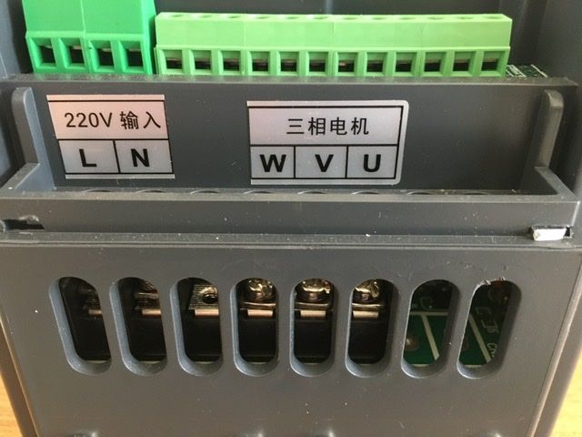
| 258 forum posts 11 photos | On my AT4 version, after some head scratching, I found the earth was located on the outer left-most terminal of the of the left hand green block above the 220v power input on your picture above- it is marked PE in minute lettering obscured by the casing (WTF!....yeah I know! …. don't start.), but don't take my word for it, check to ensure there is connection to the cooling plate. On my device, parameter 74 is 63500 and P75 is 4200 basically the span and offset values for the external control. Originally I noted these values along with other obscure parameters prior to use of the device (and a bloody good job too) seeing they were different from the 'manual'. As a test I input the values quoted in the 'manual' that were about half the 'as supplied' values and had similar half F issues. I then did a reset (bad mistake - don't ever be tempted to do one). The reset resulted in the same low values replaced in P74 and P75 (among a whole lot of other unwanted changes). I suggest you check what P74 P75 contain. If the stored values appear to be about 31000 and 1100, you could try the higher values quoted above and see if that helps and experiment from there until you are getting the range of control that you want. Above all take care, this thing is a pretty scary device to have floating around on the test bench.
Edited By Martin of Wick on 23/05/2020 23:14:06 |
| Martin of Wick | 23/05/2020 23:08:56 |
| 258 forum posts 11 photos | Hmmm.... just seen your latest post... will be most interesting to see if reducing your P74 75 parameters to manual values actually gives you back full frequency control on the external input - It would then be the exact opposite of what happened in my case! Go figure! P67 is another parameter you may need to have regard to as it is often different from the one listed in the info sheet. I didn't detect any voltage between device and mains earth when I set up |
| James Walker | 23/05/2020 23:40:27 |
| 11 forum posts 1 photos | Posted by Martin of Wick on 23/05/2020 23:08:56:
P67 is another parameter you may need to have regard to as it is often different from the one listed in the info sheet.
Martin - did you determine what P67 does? It is marked as "Voltage coefficient" in the manual. |
| Andrew Firman | 24/05/2020 11:10:22 |
| 37 forum posts 18 photos | Martin, thanks for advice, A couple of queries. Did your P 73 value also differ from manual? On my vfds supplied set at 61440 manual default 31440. P75 I need to double check, I’ve recorded a supplied setting of 5560 for one vfd and 1317 for the other. Manual default is 1130 . When you say no voltage difference between device and mains earth was that with the green PE terminal connected to mains earth? What is the measured voltage across 5v and COM terminals on your AT4?
James, my P67 supplied setting is 45000. Manual default is 28500. - ostensibly a big difference.
|
| Martin of Wick | 24/05/2020 13:19:49 |
| 258 forum posts 11 photos | Andrew, Some mistakes in my original post - I referred to P74 and P75, when I should have said P73 and P74. Originally out of the box, P73 was set at 61440 and P74 was set at 4096. And P75 was set at 4196 with P67 at 45000. I don't know what P75 and P67 do but have recorded the fact that they appear to change the reported output current and voltage on the VFD display. I checked and confirmed with a clamp on that changing P75 did also appear to change the output current very approximately inline with the observed variance in the VFD display. Couldn't check the voltage as I don't have a filtering voltmeter. As you see, all supplied values differ from the info sheet. Clearly the thoughtful manufacturers have provided a generic info sheet and couldn't be a***d to amend it for different products. When I did the unit reset, all values returned (approximately) to those on the info sheet, but the AT4 was definitely not working as it should. Normal function was only restored when I re-entered the 'as supplied' parameter values as above. On set up, I only checked to see if there was a voltage from the PE terminal ( you can actually just see it marked in your photo) to the mains earth and there was no potential, but then I wasn't expecting any - maybe I should check again because all may not be well if there is a voltage present. I didn't ever record the voltage across the VR as it didn't seem to be an issue at the time. Unfortunately, my unit is not on the bench at the moment pending works to the drill for which it was purchased for. I will see If I can cobble something up tonight and let you know.
|
| Martin of Wick | 24/05/2020 13:36:51 |
| 258 forum posts 11 photos | Just to avoid tail chasing, we are sure that it is a new and/or tested 10k Pot and that P10 is set at 2 with P11 set at 2? Edited By Martin of Wick on 24/05/2020 14:02:38 |


Please login to post a reply.
Magazine Locator
Want the latest issue of Model Engineer or Model Engineers' Workshop? Use our magazine locator links to find your nearest stockist!
Sign up to our Newsletter
Sign up to our newsletter and get a free digital issue.
You can unsubscribe at anytime. View our privacy policy at www.mortons.co.uk/privacy
Latest Forum Posts
- *Oct 2023: FORUM MIGRATION TIMELINE*
05/10/2023 07:57:11 - Making ER11 collet chuck
05/10/2023 07:56:24 - What did you do today? 2023
05/10/2023 07:25:01 - Orrery
05/10/2023 06:00:41 - Wera hand-tools
05/10/2023 05:47:07 - New member
05/10/2023 04:40:11 - Problems with external pot on at1 vfd
05/10/2023 00:06:32 - Drain plug
04/10/2023 23:36:17 - digi phase converter for 10 machines.....
04/10/2023 23:13:48 - Winter Storage Of Locomotives
04/10/2023 21:02:11 - More Latest Posts...
- View All Topics
Support Our Partners


Shopping Partners
Subscription Offer

Latest "For Sale" Ads
- Reeves** - Rebuilt Royal Scot by Martin Evans
by John Broughton
£300.00 - BRITANNIA 5" GAUGE James Perrier
by Jon Seabright 1
£2,500.00 - Drill Grinder - for restoration
by Nigel Graham 2
£0.00 - WARCO WM18 MILLING MACHINE
by Alex Chudley
£1,200.00 - MYFORD SUPER 7 LATHE
by Alex Chudley
£2,000.00 - More "For Sale" Ads...
Latest "Wanted" Ads
- D1-3 backplate
by Michael Horley
Price Not Specified - fixed steady for a Colchester bantam mark1 800
by George Jervis
Price Not Specified - lbsc pansy
by JACK SIDEBOTHAM
Price Not Specified - Pratt Burnerd multifit chuck key.
by Tim Riome
Price Not Specified - BANDSAW BLADE WELDER
by HUGH
Price Not Specified - More "Wanted" Ads...
Get In Touch!
Do you want to contact the Model Engineer and Model Engineers' Workshop team?
You can contact us by phone, mail or email about the magazines including becoming a contributor, submitting reader's letters or making queries about articles. You can also get in touch about this website, advertising or other general issues.
Click THIS LINK for full contact details.
For subscription issues please see THIS LINK.
Digital Back Issues


Donate

 Register
 Log-in
Model Engineer Magazine
- Percival Marshall
- M.E. History
- LittleLEC
- M.E. Clock

ME Workshop
- An Adcock
- & Shipley
- Horizontal
- Mill

Subscribe Now
- Great savings
- Delivered to your door

Pre-order your copy!
- Delivered to your doorstep!
- Free UK delivery!
All Forum Topics > General Questions > VFD. XSY AT4 220v 1phase to 380v 3phase advice sort