Forum sponsored by:

reversing gear
| geoff walker 1 | 18/08/2019 14:18:32 |
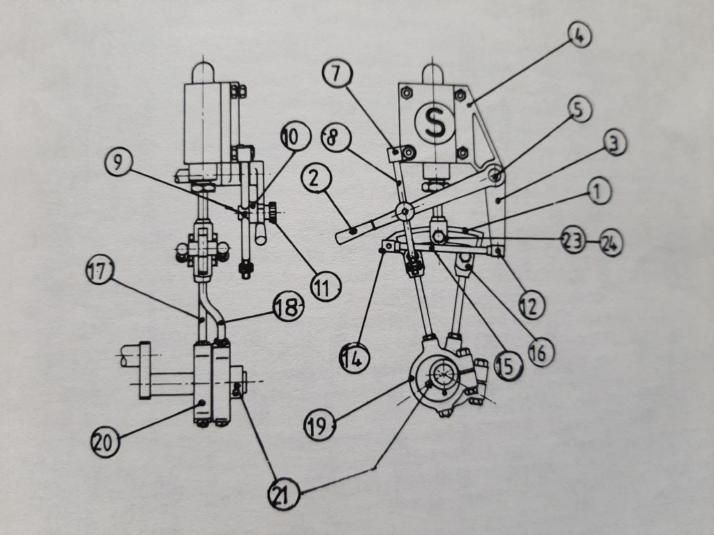
| 521 forum posts 217 photos | Hi All. I found this diagram on the internet. I'm NOT 100% sure but I think the reversing gear below is for a stuart 10v. OK, the pivot pin 5 passes through a hole in the bracket 4. On one end of the pin is attached the lever 2 and the other end the linkage 1. By releasing the knurled lock nut 11 you can raise or lower the lever to move sideways "the "part with slot in" 1, to select either forward or reverse rotation of the engine. As I see it for this mechanism to work 1 and 2 must be rigidly fixed to the pivot pin while the pin is free to pivot in the bracket hole 4? Assuming I'm correct how are 1 and 2 secured on the pivot pin? Geoff |
| malcolm wright 1 | 18/08/2019 14:46:31 |
| 4 forum posts | I believe 1 and 2 are pinned onto the piovot which is free to rotate in bracket item 4. If ypu check out Kieth Appleton on you tube he has a video on ST reversing gear.
|
| geoff walker 1 | 18/08/2019 15:06:32 |
| 521 forum posts 217 photos | Hi Malcolm, Thank you, I forgot about Keith Appleton, good video. Thanks again Geoff |
| JasonB | 18/08/2019 15:43:09 |
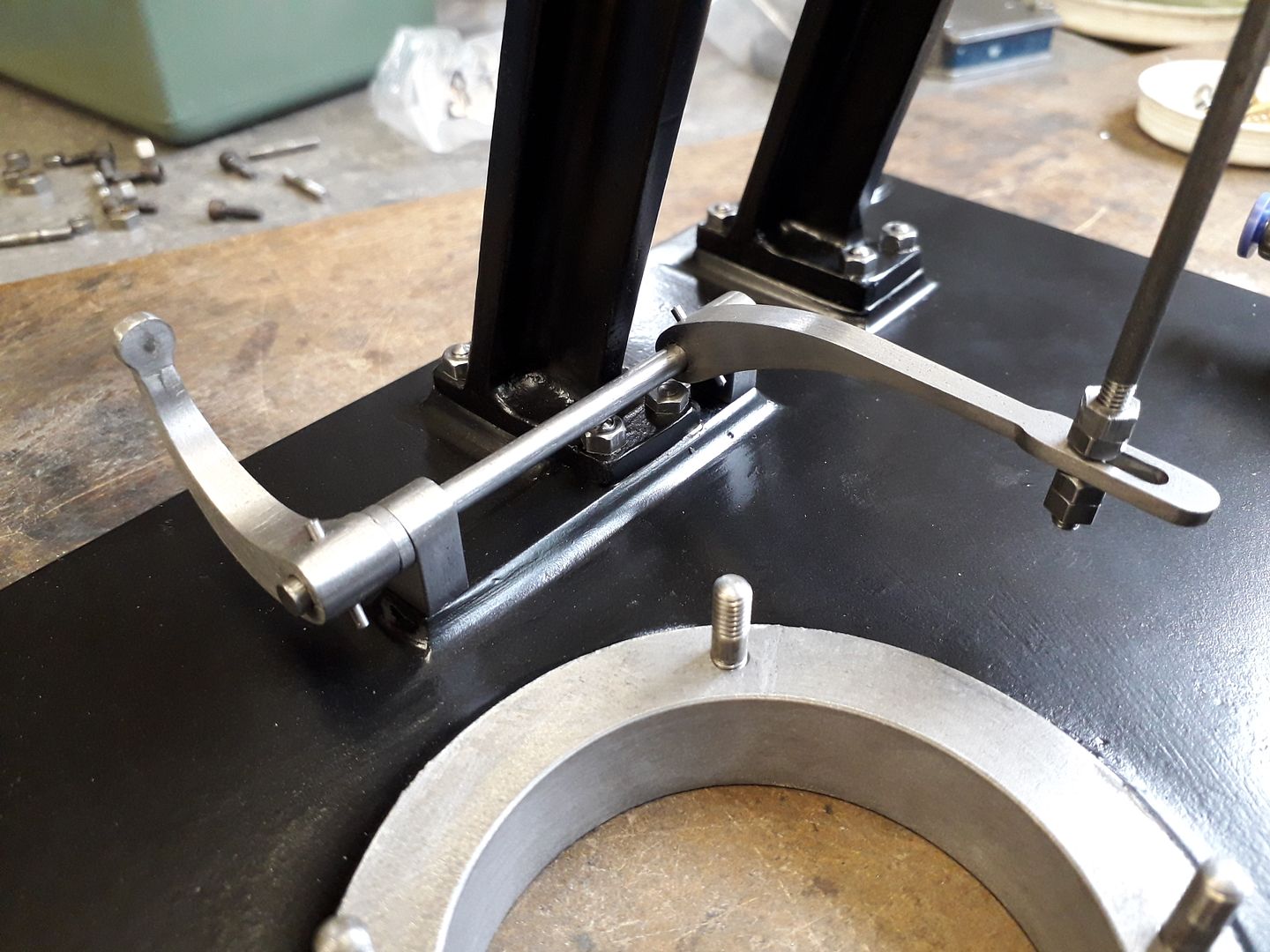
 25215 forum posts 3105 photos 1 articles | 1 is not fixed to the pivot. Lever 2 and the arm 3 form a rigid bellcrank pivoting around pin 5 so as the lever goes up and down the expansion link 1 moves sideways. On the Double 10 the pivot 5 takes the form of a rod along the length of the engine so one lever 2 will move two arms, one at either end of the engine Edited By JasonB on 18/08/2019 15:47:43 |
| Clive Brown 1 | 18/08/2019 15:49:14 |
| 1050 forum posts 56 photos | The lifting link between the bellcrank and the expansion link seems to be omitted from the LH diagram. |
| JasonB | 18/08/2019 16:26:41 |
25215 forum posts 3105 photos 1 articles | Lifting links are there, one on each side. They are round ended.
Edited By JasonB on 18/08/2019 16:28:02 |
| Clive Brown 1 | 18/08/2019 16:47:56 |
| 1050 forum posts 56 photos | Posted by JasonB on 18/08/2019 16:26:41:
Lifting links are there, one on each side. They are round ended.
Ah,sorry quite correct. I'm with it now. |
| geoff walker 1 | 18/08/2019 17:27:13 |
| 521 forum posts 217 photos | Hi Jason, Thanks for your reply. I was mistaken, as you say, it's 2 and 3 which are rigid and form the bell crank. With such small parts, I believe the pivot pin is 3/16" diameter, is there a taper pin and taper reamer small enough to pin the parts together? If not I imagine you would use small carpenters moulding pins? Geoff |
| JasonB | 18/08/2019 17:36:49 |
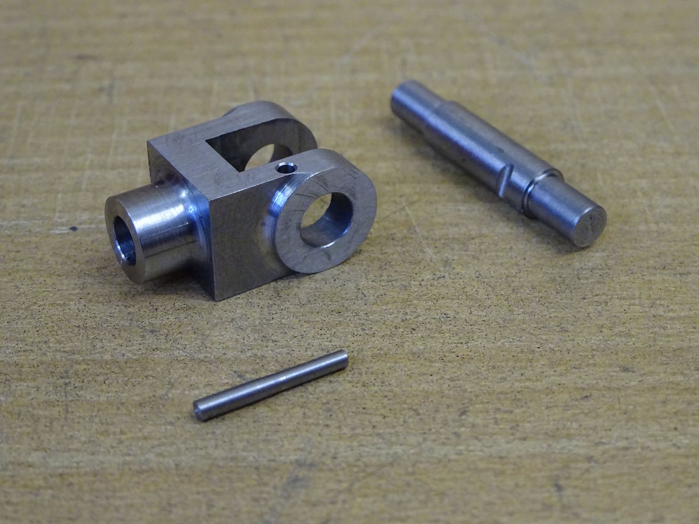
25215 forum posts 3105 photos 1 articles | At 3/16" the small end of a 1/16" taper pin will do fine. As it's such a small engine you could just drill a plain hole say 1.2 or 1.4mm and turn a parallel pin that can be stuck in with a small drop of Loctite. These taper pinsare 1/16" pins through an 5/32" rod.
Edit I don't know how much metal you have in the lever and arm bosses but on the larger Stuart No1 reverser they show the taper pin part way through the rod and not through the middle like my photo above. This also does the job and retains some strength in the rod much like this cross head pin I did a while ago.
Edited By JasonB on 18/08/2019 17:50:23 |


Please login to post a reply.
Magazine Locator
Want the latest issue of Model Engineer or Model Engineers' Workshop? Use our magazine locator links to find your nearest stockist!
Sign up to our Newsletter
Sign up to our newsletter and get a free digital issue.
You can unsubscribe at anytime. View our privacy policy at www.mortons.co.uk/privacy
Latest Forum Posts
- *Oct 2023: FORUM MIGRATION TIMELINE*
05/10/2023 07:57:11 - Making ER11 collet chuck
05/10/2023 07:56:24 - What did you do today? 2023
05/10/2023 07:25:01 - Orrery
05/10/2023 06:00:41 - Wera hand-tools
05/10/2023 05:47:07 - New member
05/10/2023 04:40:11 - Problems with external pot on at1 vfd
05/10/2023 00:06:32 - Drain plug
04/10/2023 23:36:17 - digi phase converter for 10 machines.....
04/10/2023 23:13:48 - Winter Storage Of Locomotives
04/10/2023 21:02:11 - More Latest Posts...
- View All Topics
Support Our Partners


Shopping Partners
Subscription Offer

Latest "For Sale" Ads
- Reeves** - Rebuilt Royal Scot by Martin Evans
by John Broughton
£300.00 - BRITANNIA 5" GAUGE James Perrier
by Jon Seabright 1
£2,500.00 - Drill Grinder - for restoration
by Nigel Graham 2
£0.00 - WARCO WM18 MILLING MACHINE
by Alex Chudley
£1,200.00 - MYFORD SUPER 7 LATHE
by Alex Chudley
£2,000.00 - More "For Sale" Ads...
Latest "Wanted" Ads
- D1-3 backplate
by Michael Horley
Price Not Specified - fixed steady for a Colchester bantam mark1 800
by George Jervis
Price Not Specified - lbsc pansy
by JACK SIDEBOTHAM
Price Not Specified - Pratt Burnerd multifit chuck key.
by Tim Riome
Price Not Specified - BANDSAW BLADE WELDER
by HUGH
Price Not Specified - More "Wanted" Ads...
Get In Touch!
Do you want to contact the Model Engineer and Model Engineers' Workshop team?
You can contact us by phone, mail or email about the magazines including becoming a contributor, submitting reader's letters or making queries about articles. You can also get in touch about this website, advertising or other general issues.
Click THIS LINK for full contact details.
For subscription issues please see THIS LINK.
Digital Back Issues


Donate

 Register
 Log-in
Model Engineer Magazine
- Percival Marshall
- M.E. History
- LittleLEC
- M.E. Clock

ME Workshop
- An Adcock
- & Shipley
- Horizontal
- Mill

Subscribe Now
- Great savings
- Delivered to your door

Pre-order your copy!
- Delivered to your doorstep!
- Free UK delivery!
All Forum Topics > 3D Printers and 3D Printing > reversing gear