
Emco FB 2 Earning its keep
| Graham Meek | 23/07/2019 16:39:30 |
| 714 forum posts 414 photos | I thought I would share another project with the forum. This involves garden engineering. The rear gates to my property are substantial things and originally the largest gate would open fully and run parallel with my boundary. Due to the lane surface now being higher than it used to be the gate will only open 120 degrees. While I could have had the hinges for the gates cut off and welded back on higher up, raising the gates this would allow cats and small dogs to come under the gate. Thereby creating another project to stop this. In the end I have decided that if the large gate could rise as it is being opened by about 40 mm then this would make things easier as only one gate needs modifying. Thus the FB 2 was pressed into service this week making the cam to raise the gate.
The piece of thick wall pipe is 140 mm diameter and 13.5 mm thick. The picture taken this morning was yesterday afternoons work. Hand finishing this morning finished this part of the build. I will post the next piece of the jigsaw when I have made it. Regards Gray,
|
| Joseph Noci 1 | 23/07/2019 17:12:46 |
| 1323 forum posts 1431 photos | Nice work Graham. That's the EMCO rotary table and 90deg angle plate doing the job? Just shows again what the FB2 can actually do! Presume that was co-ordinated rotary angle and X table position to rough mill the profile? How did you do the actual cut? Was it a Z plunge - if so did you use the Quill handle or move the entire head down in Z? Or did you sneek up to the cut in X only? As mentioned before, I have three FB2 'variants' and would not dispose of any! Joe
|
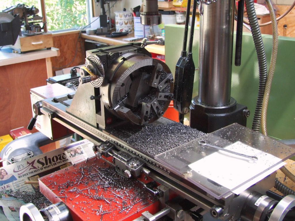
| Graham Meek | 23/07/2019 18:19:18 |
| 714 forum posts 414 photos | Hi Joe, I drilled a 6.5 mm diameter hole at every 5 degrees moving on the X axis at each location. This was the largest drill due to the centre to centre distance. You can see the plot position list, (not very clearly) under the spanner. This process was followed using a 14 mm slot drill, fed down manually using my fine feed on the quill. Finally the form was cut using a 20 mm slot drill, this cut was done using the powered down feed. I then set the rotary table over to correspond to a 2.5 degree increment and went through the same process with the powered down feed to take off the bits in between the previous cut. The last operations took just under an hour. The manual dressing to take off the peaks took about half an hour. Regards Gray,
|
| Joseph Noci 1 | 23/07/2019 18:27:32 |
| 1323 forum posts 1431 photos | Nicely Done! I am interested to see how the gate mechanism is implemented. I used cabinet hinges that have a similar spiral wedge as part of the hinge - to lift the door about 6mm to clear a tiled kitchen counter top - your 'hinge' would allow my cupboard to remain fixed whilst the entire kitchen could rotate and lift! Quite a gate you must have! Some photo's when it's all done would be educational..
Regards Joe |
| Graham Meek | 24/07/2019 12:07:30 |
| 714 forum posts 414 photos | Hi Joe, The largest gate which I am working on is 3 m long and 1.8 m high. Made from 50 mm heavy gauge box section and clad with 25 150 x 25 mm boards 1.8 m long. A conservative estimate is 0.25 Ton, but I reckon it is more than this, probably 0.4. The other two gates which are in front of the garage, are 2 m x 1.8 m and of similar construction. These fold on one another like a bi-fold door. In total my gates cover 7 m and the uprights that hold the gates have a strut brace at the top to keep the posts apart. This strut can just be seen in the photograph.
I am like IKB, I don't like to have to revisit jobs once I have done them, so there is definitely some overbuild in these gates. They have been there for nearly 40 years and other than paint the steel and treat the wood no other work has been needed. Of course I have no control over the repairs to the footpath which has prompted my current project. Regards Gray, |
| Graham Meek | 26/07/2019 10:43:19 |
| 714 forum posts 414 photos | Yesterday was a good day, despite the 33.5 C workshop temperature. The mounting plate for the Cam is now complete. The profile of the plate was an old jig base salvaged during my Toolmaking days, this includes the four counterbored holes in each corner. The various mounting holes and rotary table location holes were done earlier in the morning as was the rectangular pocket,
The extension handle for the rotary table is one I made years ago, it saves having to fumble around under a component for the table handle,
The last operation was to drill and tap an M8 stud hole, to clamp the mounting plate to the post.
Note how the job is dropped over the back edge of the table to gain room under the spindle nose and the workhead is slewed around to get to the job. There is not enough travel on the Y-Axis to allow the workhead to stay in its normal position. Regards Gray, |
| Graham Meek | 29/07/2019 21:09:59 |
| 714 forum posts 414 photos | This morning I made the final piece of the jigsaw, note the grease nipple for future lubrication, if I can bend down to get to it?
Then began the fitting of the completed parts to the gate.
Well I hope you have enjoyed my bit of Garden Engineering, there is still things to do to finish the job off. Like putting some concrete beneath the aluminium base plate and extending the hinge pins. The latter is under way but I am waiting for the loan of a right angle drill to do this operation. Regards Gray, |
| Joseph Noci 1 | 29/07/2019 21:34:02 |
| 1323 forum posts 1431 photos | Very Neat! I would like to see a photo of the swinging end of the gate and what it had to clear in the lane... You mentioned this need came about after some Council repairs to the surface. Hopefully they don't do that again! Although I guess next time you could put a 10deg inwards tilt on the gate post..
Nicely done. Joe |
| Graham Meek | 30/07/2019 10:37:09 |
| 714 forum posts 414 photos | Hi Joe, Until recently the slope or fall on the surface of the lane was towards the property boundaries on my side of the lane. The result of this is flooding to the rear of the properties. The repairs to the surface by sub-contractors over the years have added to this. The district council view is that water will flow up hill in this part of the Universe and into the french drain they installed but have no record of. It does not help that outside my boundary is the lowest point in the length of the lane, that is both ends are higher. For the past year I have been struggling to get anything done, however last month the County council installed the drain you see below and graded the lane towards it, but only in front of my boundary. The result was my gate just clipped the far corner where the ground is higher. Why not just take this bit off? Well this is a public footpath, and to tamper with this surface carries a hefty fine. Not to mention a liability for anyone who should get hurt from said tampering. Hence my solution, I doubt the council will be doing anymore repairs in front of my gates, this has been a costly lesson for them.
Regards Gray, Edited By Graham Meek on 30/07/2019 10:39:05 |
| john brown 17 | 31/07/2019 18:37:44 |
| 135 forum posts 3 photos | Fine work there graham,that should sort it out,love the dividing head and the mill. john |
| Brian G | 31/07/2019 19:14:49 |
| 912 forum posts 40 photos | There is an interesting variant on the "tilt on the gate post" here. Brian |
| Graham Meek | 01/08/2019 12:50:36 |
| 714 forum posts 414 photos | Hi John, Thanks for the compliments, the Emco Dividing Head, come Rotary Table, is a handy piece of equipment to have and it does get a lot of use in my workshop. Regards Gray, |


Please login to post a reply.
Want the latest issue of Model Engineer or Model Engineers' Workshop? Use our magazine locator links to find your nearest stockist!
Sign up to our newsletter and get a free digital issue.
You can unsubscribe at anytime. View our privacy policy at www.mortons.co.uk/privacy
- *Oct 2023: FORUM MIGRATION TIMELINE*
05/10/2023 07:57:11 - Making ER11 collet chuck
05/10/2023 07:56:24 - What did you do today? 2023
05/10/2023 07:25:01 - Orrery
05/10/2023 06:00:41 - Wera hand-tools
05/10/2023 05:47:07 - New member
05/10/2023 04:40:11 - Problems with external pot on at1 vfd
05/10/2023 00:06:32 - Drain plug
04/10/2023 23:36:17 - digi phase converter for 10 machines.....
04/10/2023 23:13:48 - Winter Storage Of Locomotives
04/10/2023 21:02:11 - More Latest Posts...
- View All Topics


- Reeves** - Rebuilt Royal Scot by Martin Evans
by John Broughton
£300.00 - BRITANNIA 5" GAUGE James Perrier
by Jon Seabright 1
£2,500.00 - Drill Grinder - for restoration
by Nigel Graham 2
£0.00 - WARCO WM18 MILLING MACHINE
by Alex Chudley
£1,200.00 - MYFORD SUPER 7 LATHE
by Alex Chudley
£2,000.00 - More "For Sale" Ads...
- D1-3 backplate
by Michael Horley
Price Not Specified - fixed steady for a Colchester bantam mark1 800
by George Jervis
Price Not Specified - lbsc pansy
by JACK SIDEBOTHAM
Price Not Specified - Pratt Burnerd multifit chuck key.
by Tim Riome
Price Not Specified - BANDSAW BLADE WELDER
by HUGH
Price Not Specified - More "Wanted" Ads...
Do you want to contact the Model Engineer and Model Engineers' Workshop team?
You can contact us by phone, mail or email about the magazines including becoming a contributor, submitting reader's letters or making queries about articles. You can also get in touch about this website, advertising or other general issues.
Click THIS LINK for full contact details.
For subscription issues please see THIS LINK.


 Register
 Log-in
Model Engineer Magazine
- Percival Marshall
- M.E. History
- LittleLEC
- M.E. Clock

ME Workshop
- An Adcock
- & Shipley
- Horizontal
- Mill

Subscribe Now
- Great savings
- Delivered to your door

Pre-order your copy!
- Delivered to your doorstep!
- Free UK delivery!