Forum sponsored by:

Norton Quick Change Gearbox Removal
| ChrisH | 03/07/2017 18:20:45 |
| 1023 forum posts 30 photos | I had a jam up on my lathe this afternoon which has caused damage somewhere in the Norton quick change gearbox - it also stripped several teeth off the input gear! The lathe is a well built German Weiler LZ 280 lathe of uncertain vintage - probably late 1960's very early 1970's. The quick change gearbox has the usual two shaft outlets, a leadscrew for screw threading on top and a splined shaft - posh term for a shaft with a longitudinal keyway - in the bottom for power feeds. I am trying to remove the gearbox to see what damage has been done and to repair it. The box has been detached from the lathe and the leadscrew is out but it is resisting all attempts to detach the power feed shaft. The manual gives no instruction for removal but states there is a "safety slip-clutch of spring-loaded key-drive design, located in the end bearing of feed shaft at quick change gear box, protection is assured against overload" (lost a little in the translation perhaps!) but the drawing is less than clear and offers little to no guidance to the shaft's removal. Where the feed shaft disappears into the box there was a circlip which I thought might be holding things back but it's removal has not helped, it doesn't want to come out and prefers to just slide through the apron as I try to pull it clear. As an extreme measure I suppose I could pull the feed shaft all the way out the apron, but then I fear the mating key might fall out and that would mean the apron would need stripping down, but before I venture down that route: Has anyone any idea how the feed shaft is removed? There has got to be an easy way - I just don't know it! All help gratefully received. Chris |
| Ian Parkin | 03/07/2017 18:57:19 |
 1174 forum posts 303 photos | Chris It sounds like the description of colchesters to removing the feed shaft..there's a spring loaded ball clutch in the shaft..as i remember you loosen an Allen screw and the ball comes out and then the shaft withdraws..any pictures of your set up? |
| ChrisH | 03/07/2017 20:40:32 |
| 1023 forum posts 30 photos | Hi Ian, No pictures as yet, will try some tomorrow - am all cleaned up and in reflective beer supping mode now! Sounds reasonable your solution, but where would the allen screw be? Not seen one, but that is not to say there isn't one. Will look again in the morning, it should be fairly visible if there is one, I would have thought. Chris |
| ChrisH | 04/07/2017 09:15:12 |
| 1023 forum posts 30 photos | OK - two photos of the problem:
So, the circlip is off and that's it. the feed shaft is still solid in the box. The little dark dot on the feed collar would suggest a pin through the shaft and it's collar, except that no pin is visible in the collar, it's just a hole down to the shaft (I think). I might try drilling through, just to be sure, it's a 2mm hole. Pulling the shaft out through the apron is not an option, the feed shaft keyway does not extend to the end of the shaft. My thought are now, if the feed shaft will not come out, I am thinking of cutting the shaft near the box, under the leadscrew sleeve above. This will free the box so I can get it to the bench. Then I will make a collar to cover the cut and secure it to both sides of the shaft with grub screws into the keyway, when it gets reinstalled Unless anyone can flag up a problem with doing this! Then at least I have a means to remove the box easily in the future, should it be necessary. I don't like the idea of cutting the shaft but I don't see an alternative. Without any bright ideas on getting the feed shaft out the box I don't know what else to do. Cannot see any allen screws to undo to release the clutch, there appears nothing obvious. More pondering to do! Chris |
| Ian Parkin | 04/07/2017 09:24:42 |
1174 forum posts 303 photos | Are you sure that the hole isn't a taper pin perhaps with a thread in to extract it...when i enlarge the picture there seems to be slight sight of a ring around the hole..the arrangement in your picture is nothing like the colchester feed shaft clutch Cutting and making a collar to span the cut would certainly work but it surely should come out easily |
| roy entwistle | 04/07/2017 09:27:16 |
| 1716 forum posts | The shaft must have been in one piece when it was installed, so, it must come out. ( don't ask me how ) Roy |
| ChrisH | 04/07/2017 09:43:39 |
| 1023 forum posts 30 photos | Ian - Either side of the hole the collar and the shaft are marked with an 'o' which to me are witness marks, which in turn suggests the shaft should come out. The hole is only 2mm diameter and it appears solid a little way down, The same the other side. I can try grinding down a pin punch to fit the hole and see I can punch it through, see if that works If not I will try drilling through the hole to ensure it's clear and then try pulling the shaft out again. I agree, it surely should come out easily, the problem is, it doesn't. Story of engineering life really! Roy - Indeed the shaft was in one piece when it went in, so it must come out. Trouble is, I don't know how it went in - I was hoping someone on here would know how, it must have been seen before. Chris
|
| KWIL | 04/07/2017 09:52:58 |
| 3681 forum posts 70 photos |
Take a look at this, the rebuild shows that the shaft should withdraw from the collar on the rt. hd. side of gearbox |
| KWIL | 04/07/2017 10:02:39 |
| 3681 forum posts 70 photos | 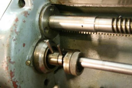 |
| Clive Foster | 04/07/2017 10:25:17 |
| 3630 forum posts 128 photos | A pin through a cross hole is common practice when joining such shafts to a bored to fit collar. Frequently the pin is made small and / or weak so that it shears when overloaded to protect the drive train. Unfortunately if a plain pin is used it can smear at the shear line between the shaft and the collar instead of breaking cleanly. If this happens things tend to twist a bit and jam up solid with the remains of the pin somewhat out of line with the holes in the collar. Given the small size of you joining pin I suspect this has indeed sheared at the joint line and smeared across so drilling out won't help. The smeared material takes up clearances and holds in against movement in all directions. Odds are it sheared one side first then the other after bending the pin slightly. The bend makes the smearing effect worse. Best way to release things is to twist the shaft relative to the collar bringing the pin back into alignment with the hole so it can be driven out. If you can get things moving can be possible to feel the smeared pin moving back into alignment with the holes for driving out. 50/50 chance if the four similar jobs I've done are typical. Anoint with plenty of plus gas or similar releasing stuff, heat, try, re-anoint, wait and have another go type job. Solid clamp on levers to hold the shaft and collar for mutual twisting will be more secure and less damaging than grips. Ideally alloy on steel as this holds better than steel on steel.. Clive PS:- KWIL posted whilst I was typing. Interesting picture and smeared pin theorry may not apply but that one looks to be slightly different design to yours. Edited By Clive Foster on 04/07/2017 10:28:35 |
| ChrisH | 04/07/2017 10:26:45 |
| 1023 forum posts 30 photos | KWIL - I was just looking at the link you posted and that exact picture. Slightly different arrangement there to mine I think, but there is a suggestion on other pictures on/in the link that at least some part of it unscrews. However on mine there are no flats or knurls to suggest a screw. The shaft MUST withdraw somehow. Are the pegs just temporary locators perhaps? I don't like butchering innocent parts but to unscrew mine I would have to use stilsons or similar to hold one bit whilst I turned another. Thinking out aloud here. Perhaps as it's been in there for so long there is a certain tightness developed? It needs another dose of 'looking at'! |
| ChrisH | 04/07/2017 10:44:28 |
| 1023 forum posts 30 photos | Clive - on the collar and on the shaft are two what I think are witness marks - a little 'o' stamped on each. They are inline with each other which made me think that the shaft hadn't twisted round. However, that is not to say it hasn't moved in or out, or even around. At the moment I haven't been able to move the shaft round relative to the collar, but I will try again - and I have Plus Gas! I hope that the pin hasn't sheared and cause a seizure, that won't help at all, but it would explain the reluctance to move. Chris PS - indeed, the picture that KWIL posted does look different to mine, but I suppose the same basic design could have changed or evolved during the production run Edited By ChrisH on 04/07/2017 10:48:23 |
| ChrisH | 04/07/2017 11:47:36 |
| 1023 forum posts 30 photos | Eureka! The feed shaft is out. Holding the collar and turning the shaft did not work but , after noticing the collar would move in and out the box a little I had a sudden inspiration. I tapped the collar inwards whilst holding the shaft and collar out and it moved relative to the shaft. Pulling the shaft and collar out then tapping the collar in, and repeating and repeating worked, the shaft slid out. And Clive, you were quite correct, there was a pin sheared in the shaft and the shaft had at some time moved out about 3mm. Pin is now removed, new 2mm dia pin to find, and I can now sort the gear box out. Just for the record, don't know what the exact internal set up is still, but there are two collars - you can see them in my pictures. When the inner collar is moved to the right it engages with the outer collar and both rotate together. When the inner collar is moved to the left it disengages with the outer collar, you can rotate it but the outer collar stays put. The outer collar provides the drive from the gearbox. It sort of helps me understand, a bit! Thank you to all who have contributed, it's nice to know there are people out there willing to help. Chris Edited By ChrisH on 04/07/2017 11:51:39 |
| Clive Foster | 04/07/2017 12:51:40 |
| 3630 forum posts 128 photos | Great that you have it out. Rather than simply replacing the pin with another 2 mm once consider re-emgineering things to avoid similar sheared pin jamming issues in future. I'd drill the holes out to 3.5 or 4 mm and make a new pin with shallow, taper sided grooves turned into it at the joint line. Threading tool with the tip rounded off worked for me. Half mm, maybe a touch more, deep should do fine. That way if it shears the break line and distortion will be contained in the holes so no smear to jam up. May still have a bit of twisting'n shifting to do to line things up before it can be punched out but that should be relatively easy. Light knurl on the collar ends held fine for me. Brass or aluminium alloy is often recommended for such pins. Never tried myself. If confident that there is no shear risk I use rollers out of scrap needle roller bearings as pins. Keep a stash primarily to use as dowel and alignment pins. Clive. |
| ChrisH | 04/07/2017 21:31:46 |
| 1023 forum posts 30 photos | Clive - have freed off the box - don't know how or even what was binding but it's freed off now - and put the lot back. Like your idea for a 'shear' type pin and will do so in due course, has a 2mm nail in at the moment just to prove the system works, no more, got to sort out the toothless gear wheel next to get a run and then we shall see if all is OK! Getting there! Chris |


Please login to post a reply.
Magazine Locator
Want the latest issue of Model Engineer or Model Engineers' Workshop? Use our magazine locator links to find your nearest stockist!
Sign up to our Newsletter
Sign up to our newsletter and get a free digital issue.
You can unsubscribe at anytime. View our privacy policy at www.mortons.co.uk/privacy
Latest Forum Posts
- *Oct 2023: FORUM MIGRATION TIMELINE*
05/10/2023 07:57:11 - Making ER11 collet chuck
05/10/2023 07:56:24 - What did you do today? 2023
05/10/2023 07:25:01 - Orrery
05/10/2023 06:00:41 - Wera hand-tools
05/10/2023 05:47:07 - New member
05/10/2023 04:40:11 - Problems with external pot on at1 vfd
05/10/2023 00:06:32 - Drain plug
04/10/2023 23:36:17 - digi phase converter for 10 machines.....
04/10/2023 23:13:48 - Winter Storage Of Locomotives
04/10/2023 21:02:11 - More Latest Posts...
- View All Topics
Support Our Partners


Shopping Partners
Subscription Offer

Latest "For Sale" Ads
- Reeves** - Rebuilt Royal Scot by Martin Evans
by John Broughton
£300.00 - BRITANNIA 5" GAUGE James Perrier
by Jon Seabright 1
£2,500.00 - Drill Grinder - for restoration
by Nigel Graham 2
£0.00 - WARCO WM18 MILLING MACHINE
by Alex Chudley
£1,200.00 - MYFORD SUPER 7 LATHE
by Alex Chudley
£2,000.00 - More "For Sale" Ads...
Latest "Wanted" Ads
- D1-3 backplate
by Michael Horley
Price Not Specified - fixed steady for a Colchester bantam mark1 800
by George Jervis
Price Not Specified - lbsc pansy
by JACK SIDEBOTHAM
Price Not Specified - Pratt Burnerd multifit chuck key.
by Tim Riome
Price Not Specified - BANDSAW BLADE WELDER
by HUGH
Price Not Specified - More "Wanted" Ads...
Get In Touch!
Do you want to contact the Model Engineer and Model Engineers' Workshop team?
You can contact us by phone, mail or email about the magazines including becoming a contributor, submitting reader's letters or making queries about articles. You can also get in touch about this website, advertising or other general issues.
Click THIS LINK for full contact details.
For subscription issues please see THIS LINK.
Digital Back Issues


Donate

 Register
 Log-in
Model Engineer Magazine
- Percival Marshall
- M.E. History
- LittleLEC
- M.E. Clock

ME Workshop
- An Adcock
- & Shipley
- Horizontal
- Mill

Subscribe Now
- Great savings
- Delivered to your door

Pre-order your copy!
- Delivered to your doorstep!
- Free UK delivery!
All Forum Topics > Help and Assistance! (Offered or Wanted) > Norton Quick Change Gearbox Removal