Forum sponsored by:

Cross-slide fixture plate considerations
| Mike Hurley | 07/03/2022 09:42:21 |
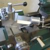
| 530 forum posts 89 photos | I have a small mill, but wanted the similar lathe facility to what you are looking into - mainly so I had some milling capacity if, for example, I had something already set up on the milling machine and didn't want to disturb that. Fortunately I had a vertical slide I had inherited but nothing to fix it to on the plain cross slide. I purchased a small CI (100 x 120 mm) milling sub-table from one of the main suppliers at a very reasonable price (sorry can't be precise who - could have been ARC, RDG etc) and fitted this using a number of M6 socket screws. It works a treat for light jobs and is reasonably versatile. In the photo you see I have removed the toolpost, this was only necessary for special access on this particular job - making some fitments for the milling machine which is currently dismantled! Normally the toolopost is attached and operates as normal. regards, Mike
|
| Alan Jackson | 07/03/2022 09:44:39 |
 276 forum posts 149 photos | Callum, I did not remake the whole cross slide, I just added 1/2" thick steel slabs with notches cut along their lengths to form tee slots. The slabs are dowelled and bolted from the underside to the cross slide. The space between the tee slots still enables access to the cross slide gib adjustment screws. The result is a slight loss of clearance over the cross slide but thats ok for me. Alan
|
| Nigel McBurney 1 | 07/03/2022 10:03:09 |
 1101 forum posts 3 photos | I would use gauge plate for the table, 12mm or 1/2 would be more than adequate,its ground flat and parallel,though expensive,tapped holes in gauge plate would last a lot longer than in aluminium. I do not see any problems using a vertical slide, I used one on my Myford to do the milling when I was building an Allchin traction engine,though I was apprentice trained so did not expect too much ,ok the Myford was new and I found accuracy was no problem and the Myford vertical slide was adequate. In the 1960s very few home engineers had a mill ,later on when I had more space I bought a milling m/c as I had moved into restoring i/c stationary engines and needed capacity plus a mill came at a reasonable price. |
| Alan Jackson | 07/03/2022 10:21:34 |
276 forum posts 149 photos | Vertical slide added
|
| Calum Galleitch | 26/03/2022 18:17:04 |
 195 forum posts 65 photos | So this turned up during the week - very well packaged from M-Machine. I took John's advice and went for steel in the end. They were out of stock of 1"x5" or 120x25mm, so I took a piece of 360mm x 3/4"x5" which fits well with just a couple of mm overhang on the sides of my cross-slide. I'll use 6 M8 cap screws to mount it.
I took my lathe to bits (again) and started plotting out where to put the screws. The thinner shell at the back is still about 12mm, so I think plenty for a 1.25 pitch thread to hold onto. At the other end, those of you who have this lathe or something similar will spot the deliberate mistake...
I spotted it as well, but not until after I'd congratulated myself for avoiding the opportunity to drill through the gib:
The problem of course is that the circular T-slot will be fouled by the location of that screw on the left. However, as I was yet to realise this, I went ahead and punched for the drill:
You can just see the circular slot through the smaller hole on the left of the large compound locating hole. I turned the slide over to check, and said some very un-ladylike words. Some gentle attention from a Dremel and a grinding bit removed the burr from the punch, and I moved the hole somewhere more sensible. And so over to the drill press. I could have just about got it in the vice but it seemed more trouble than it was worth. I have to admit I'm not a fan of this table - I'd prefer a piece of plate with through holes/slots. This thing gathers clart and small tools like no-one's business and the T-slots are fiddly (and the top section too thin - I've broken a chunk out already). I often find myself just clamping stuff down with the G-clamp.
Six holes of swarf later:
Then transfer punch the holes to the steel plate:
And drill out the steel plate for M8 thread clearance:
I hadn't thought about the fact the socket heads are 13mm in diameter, and I don't have a suitable clearance drill. I tried counterboring one hole with a 13mm drill, in the hope runout might win the day, but no. At this point I also realised (a) I had forgotten to drill clearance holes for the compound T-nuts (T-bolts?) , so did that, and (b) that although 3/4" thick steel is nice chunky stuff, it's still not enough to properly clear the bolts! I don't think it'll be a major problem, and if in the end I have to remake it in 25mm stock, well.
A 13.5mm drill to counterbore is in the post, as is (still) a set of M8 taps, so we're not quite done, but we're well on the way now. |
| Bill Phinn | 26/03/2022 19:30:26 |
| 1076 forum posts 129 photos | Is there a reason, Calum, why you don't want to use a counterbore bit to counterbore your holes? |
| Calum Galleitch | 27/03/2022 14:11:15 |
195 forum posts 65 photos | Bill, I have to confess ignorance! I didn't know such things existed, though it makes sense that they do. I think for my purposes a caphead will seat happily on the cone left behind by a drill - I don't doubt my counterbores aren't perfectly in line with the screw in the cross-slide but it should be pretty close. Having a quick look at available counterbore bits the counterbore size seems a bit large - to my mind a 13mm cap in a 15mm counterbore will look a bit spacious, and the pilot hole size seems to vary! |
| Bill Phinn | 27/03/2022 17:48:53 |
| 1076 forum posts 129 photos | Hi Calum, attached are pictures of some counterbores I did, in: M8 aluminium M5 brass M3 mild steel. My pilot and cutter diameters are respectively: 8.2mm/13.4mm 5.2mm/8.9mm 3.2mm/5.9mm
|


Please login to post a reply.
Magazine Locator
Want the latest issue of Model Engineer or Model Engineers' Workshop? Use our magazine locator links to find your nearest stockist!
Sign up to our Newsletter
Sign up to our newsletter and get a free digital issue.
You can unsubscribe at anytime. View our privacy policy at www.mortons.co.uk/privacy
Latest Forum Posts
- hemingway ball turner
04/07/2025 14:40:26 - *Oct 2023: FORUM MIGRATION TIMELINE*
05/10/2023 07:57:11 - Making ER11 collet chuck
05/10/2023 07:56:24 - What did you do today? 2023
05/10/2023 07:25:01 - Orrery
05/10/2023 06:00:41 - Wera hand-tools
05/10/2023 05:47:07 - New member
05/10/2023 04:40:11 - Problems with external pot on at1 vfd
05/10/2023 00:06:32 - Drain plug
04/10/2023 23:36:17 - digi phase converter for 10 machines.....
04/10/2023 23:13:48 - More Latest Posts...
- View All Topics
Support Our Partners


Shopping Partners
Subscription Offer

Latest "For Sale" Ads
- Reeves** - Rebuilt Royal Scot by Martin Evans
by John Broughton
£300.00 - BRITANNIA 5" GAUGE James Perrier
by Jon Seabright 1
£2,500.00 - Drill Grinder - for restoration
by Nigel Graham 2
£0.00 - WARCO WM18 MILLING MACHINE
by Alex Chudley
£1,200.00 - MYFORD SUPER 7 LATHE
by Alex Chudley
£2,000.00 - More "For Sale" Ads...
Latest "Wanted" Ads
- D1-3 backplate
by Michael Horley
Price Not Specified - fixed steady for a Colchester bantam mark1 800
by George Jervis
Price Not Specified - lbsc pansy
by JACK SIDEBOTHAM
Price Not Specified - Pratt Burnerd multifit chuck key.
by Tim Riome
Price Not Specified - BANDSAW BLADE WELDER
by HUGH
Price Not Specified - More "Wanted" Ads...
Get In Touch!
Do you want to contact the Model Engineer and Model Engineers' Workshop team?
You can contact us by phone, mail or email about the magazines including becoming a contributor, submitting reader's letters or making queries about articles. You can also get in touch about this website, advertising or other general issues.
Click THIS LINK for full contact details.
For subscription issues please see THIS LINK.
Digital Back Issues


Donate

 Register
 Log-in
Model Engineer Magazine
- Percival Marshall
- M.E. History
- LittleLEC
- M.E. Clock

ME Workshop
- An Adcock
- & Shipley
- Horizontal
- Mill

Subscribe Now
- Great savings
- Delivered to your door

Pre-order your copy!
- Delivered to your doorstep!
- Free UK delivery!
All Forum Topics > Workshop Tools and Tooling > Cross-slide fixture plate considerations