Forum sponsored by:

Clock Stand with a difference
| Graham Meek | 16/10/2021 16:25:39 |
| 714 forum posts 414 photos | I have managed to finish the Slider today, so took the opportunity to do a second check for Perpendicularity. Since posting on here last John Slater drew my attention to "Monday Night Meatloaf 116 P2" on YouTube. Tom Lipton is making a similar dedicated device and has a novel way of checking the perpendicularity. I had watched this sometime ago but forgot all about it in the interim, so I must thank John for refreshing my memory and saving me some work.
Rather than make something as Tom does in his video, I have used a piece of M8 Studding (Allthreads) and one of my Milling clamps to give the same results. Note the Ball bearing to give point contact at the top of the Column.
In this initial set-up I had an light reading, (error), of 0.005 mm at what will be the front of the Clock Stand. This I expected as my first tests before showed a slight lean on the Column of this magnitude towards the centre of the Clock Stand. The clock is sweeping a 200 mm diameter circle and the location points in the FB2 shots were about this distance apart. Rotating the Clock Stand through 180 degrees and repeating the check showed a similar error but this time it was only 0.003 mm. I know from the report that came with my surface plate that it has a slight hump. Thus when it comes to chasing these sort of errors there comes a time when it has to be accepted that this is good enough for the workshop concerned and any further work is meaning less. One thing this check does show is that the first set-up using the FB2 Mill is a sound one. Regards Gray, |
| Howard Lewis | 16/10/2021 17:09:33 |
| 7227 forum posts 21 photos | A good job, Graham! To get within a few microns in a home workshop is excellent accuracy, and as stand for a clock, it will not be subjected to the forces that might be involved if it were used a height gauge to scribe lines. As usual, WELL DONE! Howard |
| Martin Kyte | 16/10/2021 17:49:19 |
 3445 forum posts 62 photos | Nice one Gray. Apart from making a very useful instrument it's a very clear demonstration of prescision setting up techniques. regards Martin |
| Graham Meek | 16/10/2021 19:41:52 |
| 714 forum posts 414 photos | Thanks Howard & Martin for the kind words, I used the Clock Stand Column the other day to check out the Geometry of the FB2 Main Column. Using a clock in the collet holder and traversing over the Clock Stand Column using the Z-Axis. I have always known there was an error but without something truly perpendicular it has not been possible to check this before. I had thought the error was quite a bit larger than I eventually measured, but at 0,02 mm, (in the Y-Axis Plane) over the entire Z-Axis travel I am happy with that. In the X-Axis Plane it is possible to adjust for a zero reading. It will be easier once I have installed the drive mechanism to traverse the Slider on the Clock Stand. Then any clock can be held in the Slider and traversed vertically over the item being checked. I have ear-marked the Emco Angle plates as the first items to get this treatment and to finally be rectified. Regards Gray,
|
| Graham Meek | 24/03/2023 15:32:08 |
| 714 forum posts 414 photos |
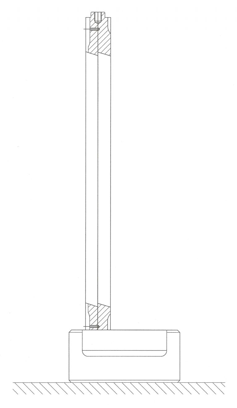
I have finally managed to finish the Multipurpose Clock stand. The clock fitted in the above photograph reads 0.002 mm and was a given to me by a friend. When using this in my Starrett Scribing Block I could seldom get the same reading twice. The weight, stability and improved locking mechanism on the above clock stand has made it all worth the effort. The clock now gives the same reading time after time.
This next photograph shows the Slider to Read-out connection. I am indebted to John Slater for this suggestion. It is piece of Pinion Wire and allows the two units to move laterally independent of each other. I am also indebted to Ketan for supplying the DRO after an enquiry for a drawing. As I have stated previously this was only added as an after thought on my part. The mounts for which are dead easy to make. This shot also shows Locking Knob which works on a separate shaft and thus does not influence the clocks setting. The Locking pad is spring loaded which always ensures a constant pressure on the rear face of the Column by the Slider.
This shot shows the Handwheel in the inboard position which gives a direct, or rapid traverse.
Pulling the Handwheel out engages a reduction drive of 4:1 for slow traverse and clock or DRO setting. The traverse is taken care of by an MXL toothed belt sunk into the Column. There is a tensioning adjustment incorporated in the top belt anchorage.The belt being sunk into the column ensures the teeth are always kept clean. The drive I was expecting to be a little Notchy but in the end my worries were unfounded.
This check was to verify the perpendicularity of my work. Running the DTI up the side of my homemade Cylinder Square and then turning the Cylinder through 180 degrees showed no error. Which was very satisfying.
The DTI can be mounted in the Vertical and used to check heights of components. Both as a comparator or in conjunction with the DRO.
This shows the scriber fitted for use as a digital Height Gauge. It takes literally seconds to change from one to the other. The scriber proper is a separate piece bolted to the end of the holder.
Finally checking the perpendicularity of the Proxxon Milling machine Column. While the clock position is not ideal and no reading at such an angle could be trusted. Using the clock in conjunction with the feedscrew does give a quantifiable reading. Which in this case was a lean backwards of 0.03 mm over 150 mm plus of vertical travel. Given the weight of the milling head this will probably rectify this error. I hope you have enjoyed this little device. Regards Gray, |
| Martin Kyte | 24/03/2023 15:49:50 |
3445 forum posts 62 photos | What a superb instrument and beautifully executed. I do hope I will get a suitable fitted case. regards Martin |
| Graham Meek | 24/03/2023 17:15:02 |
| 714 forum posts 414 photos | Posted by Martin Kyte on 24/03/2023 15:49:50:
What a superb instrument and beautifully executed. I do hope I will get a suitable fitted case. regards Martin Thanks Martin, I had not considered making a case, but it would be nice to give it a good home. Regards Gray, |


Please login to post a reply.
Magazine Locator
Want the latest issue of Model Engineer or Model Engineers' Workshop? Use our magazine locator links to find your nearest stockist!
Sign up to our Newsletter
Sign up to our newsletter and get a free digital issue.
You can unsubscribe at anytime. View our privacy policy at www.mortons.co.uk/privacy
Latest Forum Posts
- *Oct 2023: FORUM MIGRATION TIMELINE*
05/10/2023 07:57:11 - Making ER11 collet chuck
05/10/2023 07:56:24 - What did you do today? 2023
05/10/2023 07:25:01 - Orrery
05/10/2023 06:00:41 - Wera hand-tools
05/10/2023 05:47:07 - New member
05/10/2023 04:40:11 - Problems with external pot on at1 vfd
05/10/2023 00:06:32 - Drain plug
04/10/2023 23:36:17 - digi phase converter for 10 machines.....
04/10/2023 23:13:48 - Winter Storage Of Locomotives
04/10/2023 21:02:11 - More Latest Posts...
- View All Topics
Support Our Partners


Shopping Partners
Subscription Offer

Latest "For Sale" Ads
- Reeves** - Rebuilt Royal Scot by Martin Evans
by John Broughton
£300.00 - BRITANNIA 5" GAUGE James Perrier
by Jon Seabright 1
£2,500.00 - Drill Grinder - for restoration
by Nigel Graham 2
£0.00 - WARCO WM18 MILLING MACHINE
by Alex Chudley
£1,200.00 - MYFORD SUPER 7 LATHE
by Alex Chudley
£2,000.00 - More "For Sale" Ads...
Latest "Wanted" Ads
- D1-3 backplate
by Michael Horley
Price Not Specified - fixed steady for a Colchester bantam mark1 800
by George Jervis
Price Not Specified - lbsc pansy
by JACK SIDEBOTHAM
Price Not Specified - Pratt Burnerd multifit chuck key.
by Tim Riome
Price Not Specified - BANDSAW BLADE WELDER
by HUGH
Price Not Specified - More "Wanted" Ads...
Get In Touch!
Do you want to contact the Model Engineer and Model Engineers' Workshop team?
You can contact us by phone, mail or email about the magazines including becoming a contributor, submitting reader's letters or making queries about articles. You can also get in touch about this website, advertising or other general issues.
Click THIS LINK for full contact details.
For subscription issues please see THIS LINK.
Digital Back Issues


Donate

 Register
 Log-in
Model Engineer Magazine
- Percival Marshall
- M.E. History
- LittleLEC
- M.E. Clock

ME Workshop
- An Adcock
- & Shipley
- Horizontal
- Mill

Subscribe Now
- Great savings
- Delivered to your door

Pre-order your copy!
- Delivered to your doorstep!
- Free UK delivery!
All Forum Topics > Manual machine tools > Clock Stand with a difference