Forum sponsored by:

Intended function of gib screws
| Bill Phinn | 19/01/2019 00:30:25 |
| 1076 forum posts 129 photos | Many thanks for everyone's further contributions.
Neil, I'll check what thread the gib screws are tomorrow and see if I have anything matching that can be fashioned into a temporary thumbscrew for the middle position.
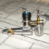
Dave, Mick and Clive, there is a substantial guide rod for the moving jaw. I've uploaded a photo, which hopefully shows it.
Clive, special thanks for the photos! I've bolted mine to a piece of wood and have it clamped to the drill table with hold-down clamps.
I did some experimental drilling and tapping on a piece of 1/4 inch mild steel bar. The set-up is solid and would, I think, be perfectly acceptable for the workaday kind of tapping my crude engineering skills currently limit me to doing - if only I could lock the slides!
As it is, virtually every time I changed over from drill bit to tap the whole plot had contrived to move a fractional amount meaning that the tap was not entering the drill hole perfectly centrally.
In desperation I decided to have a go locking the slides by tightening down the Nyloc nuts holding the handles on (pictured). This seemed to secure the two axes ok, but, however gently I wielded the spanner, by the time I had tightened the nuts the necessary two revolutions to lock things up I found that invariably one or both axes had shifted slightly out of position. Without an effective way of locking the slides I'm reduced to a lot of trial and error in order to get back exactly into the hole I'm working on.
I've not had a response from the retailer. I'm going to play around with the vice some more over the weekend and see how I feel about it in a couple of days.
|
| Clive Foster | 19/01/2019 11:55:46 |
| 3630 forum posts 128 photos | Bill. Definitely overthinking this. Fit some lock screws and she'll be fine. Use a flat, angle ended, pusher between screw and gib GHT style to give an even force over a reasonable area. The pointed end on a gib adjustment screw concentrates the force rather ineffectively over a small area, deforms the receiving dimple in the gib and risks bending the gib itself which isn't exactly helpful. I've had to deal with the results of such practices when refurbishing a lathe cross-slide gib that simply wouldn't adjust any sense. The bits supplied weren't pretty. It got a new, straight gib and the full GHT treatment after a Clive Super-scrub clean. Recipient said some really nice things about the results and now has a seriously overinflated view of my abilities. Nip the gibs up a bit tight so movement is on the stiff side and accept that you will be positioning by eye. Co-ordinate drilling is probably possible if you fit some cheap readout on stick scales but, realistically, that is moving into taking the porker to the beautician territory. If you can, do make or buy a set of proper V groove prismatic vice jaws like mine. Vastly better than the style you have and much more tolerant of grabbing uneven parts. Despite the relatively small contact areas I've not had an issues with marking work. I really don't like the very thick base. Although its theoretically nice to have the handle clear of the table where-ever its put in practice a right size cross vice for the machine will pretty much invariably end up with the handle overhanging the table anyway. The overthick base and your, essential, block of wood are costing you about 2 inches of valuable drill clearance. Last thing. For my peace of mind, please junk the Mole / Vice grip lever clamps and bolt it down. They can relax under vibration and self release like a fly off handbrake. Seen that happen. By the grace of God just major fright time for the person concerned not injury. Those clamps are great when used as intended in single grip mode. Clamp, do the job release, re-clamp for next job. So you know they are tight "right now" before starting. Leaving to hold hoping it will be fine for long periods is just too chancy. Clive. |
| Fowlers Fury | 19/01/2019 12:46:32 |
 446 forum posts 88 photos | Whilst preparing this I see Clive has replied - all of which is good ! Bill., you wrote, "......had tightened the nuts the necessary two revolutions to lock things up I found that invariably one or both axes had shifted slightly out of position." Regarding my earlier reference to the Geo Thomas write-up on gibs. He laid emphasis on the shape of the ends of gib adjusting screws and the holes (in the gibs) on which they contact. It was his view that it was important to prevent what he termed a "wedging action" whereby when adjusting - the gibs would move 'laterally' as it were. I've no wish to be critical, but from your images, I wouldn't consider your drill press column or table as 'substantial' in relation to the set up shown. In addition to Clive's suggestions, it might be worth using a heavy block of wood under the table to prevent flexing when doing any heavy drilling. Edit: Loads of distortion with the small camera used - the table is not at angle to the column ! Edited By Fowlers Fury on 19/01/2019 12:50:28 |
| Bill Phinn | 20/01/2019 17:27:05 |
| 1076 forum posts 129 photos | Thanks a lot for the further replies and suggestions. I've now brazed wing nuts on to the ends of lengths of M6 rod and rounded the other ends as evenly as I can with basic tools. The carriages now seem to lock adequately for staying centred on a hole between operations.
Clive, I can't quite visualize what you mean by "a flat, angle ended, pusher between screw and gib GHT style". I suspect this may involve machining skills or machinery I don't currently have.
Any suggestions as to where to source suitable v jaws would be appreciated. I had a mind to use my v blocks for securing round stock of any appreciable thickness.
FF, I've really only got my previous (lamentable) bench drill to compare with, so my saying the set up is solid is admittedly only a relative term. For heavy work I'll definitely follow your suggestion to use support from below.
I'd be interested to know where you got your x-y table or where one of decent quality can be had. Thanks again.
|
| Clive Foster | 20/01/2019 17:58:03 |
| 3630 forum posts 128 photos | Bill Re flat, angle ended pusher. The gib strip is at an angle relative to the tapped hole(s) for adjusting screws and, if fitted, locking screw. An ordinary, more or less flat ended screw will only contact the gib over a small area near the top. A pusher in front of the screw with the end cut to the same angle as the gib will give full contact over the whole area of the end. Clearly much more satisfactory. A single Vee block will work well to hold round stock whether vertical or horizontal. Have a search for prismatic vice jaws. Seem to be several suppliers for the 4" cross vice. Larger ones may be harder to find. This one from Grizzly **LINK** is pretty typical. The two end vertical Vees seem to be the same size tho'. Mine has three sizes of vertical Vee with the smallest one being noticeably smaller than the one at the other end. I prefer my version. I'm unconvinced as to whether just using one prismatic jaw as most suppliers suggest is completely satisfactory. But my drill is heftier than what most Home Shop types have. Clive. Edited By Clive Foster on 20/01/2019 17:58:28 |
| Danny M2Z | 20/01/2019 18:00:37 |
 963 forum posts 2 photos | Posted by Fowlers Fury on 19/01/2019 12:46:32:
Regarding my earlier reference to the Geo Thomas write-up on gibs. He laid emphasis on the shape of the ends of gib adjusting screws and the holes (in the gibs) on which they contact. It was his view that it was important to prevent what he termed a "wedging action" whereby when adjusting - the gibs would move 'laterally' as it were. As a variation on this method I found that replacing the gib screws on my mini-lathe with cup-point screws and inserting a small ball bearing into the dimple was a simple and very useful modification. I had considered dowelling the gibs but now think that this is no longer necessary. * Danny M * |
| HOWARDT | 20/01/2019 18:31:52 |
| 1081 forum posts 39 photos | Regarding the grubsrew end form. Both will work equally as well, since there is more than one screw in contact. Any error in position between the gib dimples and the tapped holes means contact will made on one side with posibly the first tightened having full position contact. |
| Fowlers Fury | 20/01/2019 18:44:20 |
446 forum posts 88 photos | Bill...."I'd be interested to know where you got your x-y table or where one of decent quality can be had". As before, I purchased mine at one of Warco's sale days - quite a bargain. However and subject to correction, I cannot find that item on their website now. |
| Clive Foster | 20/01/2019 19:39:01 |
| 3630 forum posts 128 photos | Posted by HOWARDT on 20/01/2019 18:31:52:
Regarding the grubsrew end form. Both will work equally as well, since there is more than one screw in contact. Any error in position between the gib dimples and the tapped holes means contact will made on one side with posibly the first tightened having full position contact. Um. Nope not really. Sort of true if gib screws are exactly aligned with the receiving dimples in the gib with both being cleanly shaped and undamaged. In practice, especially on more affordable a machines sufficiently perfect alignment is unlikely. Taper gibs took over, initially on industrial machines, not because they are inherently better but because they are cheaper to make once more than "OK when new I suppose" or "Fine if carefully set-up" quality is needed. Highest quality conventional parallel gib systems like the double doweled assemblies on my Smart & Brown 1024 are clearly very expensive to make because each assembly has to be made and fitted individually. Taper set-ups can be machined to suit a standard gib using ordinary series production methods. Theoretically Smart and Brown style gibs can run with closer clearances than taper ones. About half as a taper gib needs space for an oil film both sides if it is to be adjusted. Whether its really worth the effort I know not. I supposed the sliding gib block style used for a while on some Colchesters is theoretically the best but making it well enough to prove the point is probably a nightmare as more surfaces need to be machined accurately. At the lower end the simple pointed screw in dimple system works quite well enough given sympathetic adjustment. Inevitably the points and dimples slowly wear as the gib shuffles back and forth fractionally when the direction of slide movement changes. Very slowly if proper adjustment is maintained. Faster if left to run slack. Eventually screw points and dimples wear sufficiently asymmetrically to make adjustment difficult and perfect setting impossible. Whatever your views on the engineering niceties most folk would agree a couple of decades or so of good performing life is a pretty reasonable trade off for a machine you can actually afford. What really doesn't help is when Harry the Hamfisted gets short tempered with the adjustment and winds the screws up way too tight. Bent, partially flattened points on the screws with relatively deep matching gouges in the dimples are seriously not a recipe for easy, effective and accurate adjustment! Time for the GHT treatment. I've applied it to machines so badly abused that the original gib screws would only lock at full turn intervals where damaged tips and gouged dimples aligned. Thats where slight positioning mismatches between screw and dimple really turn round and bite. Danny Dowelling the gibs will improve performance even after your ball bearing drive modification. More in longer time between adjustment and longer life than anything noticeable right now I suspect. Although the ball bearing modification is theoretically inferior to the full GHT treatment it's far more tolerant of slight mismatch between dimple and screw position. GHT requires that the screw and gib countersink holes are positionally matched to very close limits to get the full benefits. I've always considered it essential to make a new, close fitting, gib and clamp everything up into the working position with the gib hard up into the top of the dovetail so the countersunk recesses can be produced in exactly the right place by drilling through the screw holes. Best way is to drill out the old screw threads and fit timesert thread inserts after producing the recesses. But thats going a bit far even for me. Clive. |
| Bill Phinn | 20/01/2019 22:53:06 |
| 1076 forum posts 129 photos | Thanks to all for the ongoing responses.
Clive, a pusher in front of the screw with a face at the same angle as the gib makes a lot of sense, though I imagine some fairly drastic machining work would have to be done on the gib strips of this vice in order to incorporate such pushers.
One thing that did occur to me fairly early on after taking out the gib screws was why not do away with any dimple (or make it a groove) and make the taper angle of the screw tips correspond with the angle of the gib? In my case, the gibs are angled at 60 degrees, whilst the included angle of the screw tips is 75. Why not just make the included angle of the tip 120 degrees, so that all of the taper is in contact with the gib, not just a tiny portion of tip? I suspect I'm missing something very basic here.
FF, sorry, yes, I did read what you had said about getting your compound table from Warco, but it had slipped my mind by the time I came to write my last post. Co-incidentally, I was looking at a review only yesterday of the one you link to on Fleabay: https://m.youtube.com/watch?v=4Mof7xcZAEQeBay: https://m.youtube.com/watch?v=4Mof7xcZAEQ
Even more co-incidentally, I notice that only a few days ago someone has left a negative review of this vice on the retailer's site, mentioning that it needs a slideway lock. It wasn't me who left the review, but of course I'd be tempted to say something very similar if I did leave one. |
| Fowlers Fury | 21/01/2019 00:00:30 |
446 forum posts 88 photos | Bill, thanks - it was interesting to view that YouTube vid you posted on the X-Y table. |
| Clive Foster | 21/01/2019 00:04:35 |
| 3630 forum posts 128 photos | Bill Matching screw tip to gib taper is a sound idea but you still only have line contact so its not hugely better. No need to machine the gib for a flat face pusher. You just fit another screw where convenient so the angled end of the pusher works direct on the flat face of the gib. Clive. |
| Nicholas Farr | 21/01/2019 00:24:13 |
 3988 forum posts 1799 photos | Hi Bill, I saw one of those on Warco's stand at Ally Pally, although they don't seem to list them. To me the height to footprint ratio seems wrong. I have two of the more conventional type, which have a lower base height to footprint ratio, which I prefer, **LINK** which I bought from Graham Engineering many years ago, which I've found to be OK for general purpose use and they have locking thumb screws that work. Regards Nick. Edited By Nicholas Farr on 21/01/2019 00:44:40 |
| Clive Foster | 21/01/2019 09:58:54 |
| 3630 forum posts 128 photos | The Warco cross vice in Nicks link looks pretty much identical to mine. But mine is larger than the Warco offerings with 6 inch, 125 mm, nominal width jaws. Yup the lock screws do work! Definitely agree that this is the best type. The disadvantage relative to the taller type is that the lower handle will argue with the drill table unless the vice is either spaced up or arranged so that it overhangs. Arranging handle overhang can be difficult if using a smaller version but, if you do need a spacer block, its effectively no different from having the taller type anyway so I see little point in buying a tall one. I can't see the point of getting a small one. They are all close to the same depth so it seems far more sensible to get a big one with decent travels and capacity. My 6" is barely big enough to be generally useful. In retrospect I'd have been happier with an 8" one which appear to be unicorn rare. Yes big ones are heavy but they are all weighty enough to need rack, screw drive or hydraulic drill table lift assistance. Clive. |
| Bill Phinn | 22/01/2019 16:40:47 |
| 1076 forum posts 129 photos | Thanks, FF, Nick and Clive. To update, the retailer has agreed to give me a gift card by way of compensation, and the listing description has been amended to remove the claim that the vice as sold has "lockable slideways". Edited By Bill Phinn on 22/01/2019 16:47:28 |
| David Lisle | 31/12/2019 17:52:24 |
 1 forum posts | My first ever cross slide vice, Chinese or Korean made and so sloppy. The main problem I have is that on the vice the gibs just slide along with the vice and come out either side depending on direction. How on earth do I stop that. Any advice would be better than fiddling with it interminable before I can drill a hole. |
| SillyOldDuffer | 01/01/2020 10:29:22 |
| 10668 forum posts 2415 photos | Hi David, The gibs should have dimples - shallow holes - which the points of the gib screws engage to stop the gibs sliding out, as in Fowler's picture:.
Most likely the gib screw points aren't in their dimples - it's a fiddle to get the screws aligned with their holes. On a cheap tool where assembly is rushed, worth confirming the gibs have dimples and that the gibs are the right way round. Now for the bad news! So far, my cross-slide vice is the most useless tool I've ever bought. I got one for my pillar drill, the idea being to improve accuracy. Not so! On an inexpensive pillar drill it's better to let the drill float into a centre-pop and find it's own way by allowing the job to move slightly to align with the spinning axis. (Harder to describe than do, and needs a little practice.) The idea is, rather than trying to force the drill into alignment by moving the job with the cross-slide, the job is permitted just enough movement to align itself with the spinning drill. Once mastered the technique is remarkably accurate, even with a wobbly drill spindle. My guess is that cross-vices fail to satisfy me for a combination of reasons: a tall bendy tower structure, relatively crude X,Y adjustment, and although not rigid enough to control the drill as a milling table would, they are rigid enough to spoil the float into alignment method described above. If cross-vices have a use, I haven't found it: can anyone put me right? Dave |
| Clive Foster | 01/01/2020 11:18:29 |
| 3630 forum posts 128 photos | As Dave (SoD) says a bit of slack in the mounting set-up isn't entirely bad as it lets the the drill accurately find the centre of the pop mark. Accurate co-ordinate drilling is the province of milling machines anyway. Unfortunately float into alignment needs a reasonable size drill. Small ones just deflect. So for small drills its better to have a nicely controlled movement with minimal float so you can set it in there right place. My cross vice is just about good enough to get small drill aligned without too much verbal encouragement whereupon the slide locks are adequate to hold things in place. That said I've had the makings of something better lying about for maybe 20 - 30 years but its never been quite annoying enough for me to make an improved version. Doesn't help that I can't make up my mind what to do about a vice. A pukka milling vice has too little opening for its size and ordinary drill vices are generally too flimsy for my tastes. If it ever gets done I shall probably either take serious inspiration from the Chick with its side locking arms or make up the wide range shaper vice published in Popular Mechanics issue dated March 1922, (Volume 37) sized appropriately for my use. When I re-do gib strips for hemispherical ended screws I force the the nascent strip up to the top of the dovetail recess and lock in place by clamping the slide over to one side. I drill through the screw holes with a centre drill leaving an accurate conical recess. Alignment assured and the hemispherical head working in the plain cone not only gives reliable adjustment with good feel but also pushes the gib up to the top of the dovetail recess adding a bit more stability. Objectively the cup ended screw with a ball in front isn't ultimately as rigid as a proper hemispherical ended screw but so long as its rigid enough the difference is immaterial. Much easier to source the parts. Clive |


Please login to post a reply.
Magazine Locator
Want the latest issue of Model Engineer or Model Engineers' Workshop? Use our magazine locator links to find your nearest stockist!
Sign up to our Newsletter
Sign up to our newsletter and get a free digital issue.
You can unsubscribe at anytime. View our privacy policy at www.mortons.co.uk/privacy
Latest Forum Posts
- *Oct 2023: FORUM MIGRATION TIMELINE*
05/10/2023 07:57:11 - Making ER11 collet chuck
05/10/2023 07:56:24 - What did you do today? 2023
05/10/2023 07:25:01 - Orrery
05/10/2023 06:00:41 - Wera hand-tools
05/10/2023 05:47:07 - New member
05/10/2023 04:40:11 - Problems with external pot on at1 vfd
05/10/2023 00:06:32 - Drain plug
04/10/2023 23:36:17 - digi phase converter for 10 machines.....
04/10/2023 23:13:48 - Winter Storage Of Locomotives
04/10/2023 21:02:11 - More Latest Posts...
- View All Topics
Support Our Partners


Shopping Partners
Subscription Offer

Latest "For Sale" Ads
- Reeves** - Rebuilt Royal Scot by Martin Evans
by John Broughton
£300.00 - BRITANNIA 5" GAUGE James Perrier
by Jon Seabright 1
£2,500.00 - Drill Grinder - for restoration
by Nigel Graham 2
£0.00 - WARCO WM18 MILLING MACHINE
by Alex Chudley
£1,200.00 - MYFORD SUPER 7 LATHE
by Alex Chudley
£2,000.00 - More "For Sale" Ads...
Latest "Wanted" Ads
- D1-3 backplate
by Michael Horley
Price Not Specified - fixed steady for a Colchester bantam mark1 800
by George Jervis
Price Not Specified - lbsc pansy
by JACK SIDEBOTHAM
Price Not Specified - Pratt Burnerd multifit chuck key.
by Tim Riome
Price Not Specified - BANDSAW BLADE WELDER
by HUGH
Price Not Specified - More "Wanted" Ads...
Get In Touch!
Do you want to contact the Model Engineer and Model Engineers' Workshop team?
You can contact us by phone, mail or email about the magazines including becoming a contributor, submitting reader's letters or making queries about articles. You can also get in touch about this website, advertising or other general issues.
Click THIS LINK for full contact details.
For subscription issues please see THIS LINK.
Digital Back Issues


Donate

 Register
 Log-in
Model Engineer Magazine
- Percival Marshall
- M.E. History
- LittleLEC
- M.E. Clock

ME Workshop
- An Adcock
- & Shipley
- Horizontal
- Mill

Subscribe Now
- Great savings
- Delivered to your door

Pre-order your copy!
- Delivered to your doorstep!
- Free UK delivery!
All Forum Topics > Workshop Tools and Tooling > Intended function of gib screws