Forum sponsored by:

Making a Dickson style QCTP
| Clive Foster | 08/08/2017 18:29:36 |
| 3630 forum posts 128 photos | Can't see the short locking spanner of a Dickson set putting enough force on the system to create any elastic deflection. Its actually held by the common jam-cam system where two steel meters are rotated together with the tangent of the contact angle between the components is sufficiently less than the co-efficinet of friction for things to hold tight. Same as the effect that fixes self holding (Morse et al) tapers. Fundamentally a Dickson holds for the same reasons as a cam-lock chuck mount and no-one complains about them. OK the chuck mount has three locks not one, but they are smaller, and the alignment geometry is round not straight line. From force consideration its the same tho'. Agree with Murray about the impracticality of making your own Multifix style set-up. Pretty convinced that the alleged superiority of the Multifix system is mostly because it has to be made properly and precisely to work at all. Dickson style is relatively easy to do and sufficiently forgiving that any firm with adequate grinding capabilities can have a go. I suspect that Multifix users were typically at the higher end of the market too where folk could be expected to take more care. Being so common there were plenty of careless Dickson users out there who never bothered to clean things or use the device properly by holding the tool carrier up against the post before pulling the lock on. If its filthy with swarf and just pulled up by the lock its not surprise if its shits. But usually they don't. Seen them soldiering on despite being so jammed up with swarf inside that the lock would barely move. Clive |
| Neil Wyatt | 08/08/2017 18:46:27 |
 19226 forum posts 749 photos 86 articles | Posted by Clive Foster on 08/08/2017 12:53:09:
Neil Sorry, nope! End up with a narrow guide system which is less rigid. Harder to machine too as its a Vee - flat system like a conventional lathe bed. Vee - flat system constraints are horrible if you want secure, accurate interchangeably. Four precision constraints on each part, all struck off a master plane. There is a reason why lathe beds and saddles have, historically, always been scraped to fit as pairs. SouthBend, past masters of inexpensive precision knew exactly what they were doing in using twin Vees on their beds. If you want a single Vee then the other side needs to be flat against a part spherical curve. Not nice in that sort of job for many reasons. The whole point of the Dickson system is that, in principle, it requires only that the Vees be parallel and the overall layout geometrically sensible. Clive. How does removing one of the four surfaces make it harder to machine or less likely to align? The Dickson system doesn't just require the vees to be parallel (reasonably easy) but exactly the same depth and exactly the same distance apart (rather more challenging). Neil |
| Speedy Builder5 | 08/08/2017 19:03:16 |
| 2878 forum posts 248 photos | A bit late on the discussion, but I was taught that Kinematic design could only allow 3 touching faces, so if you have 2 "Vs" i.e. 4 faces, then only 3 of them can touch at any one time. And hence the three legged milking stool, camera Tripods and Robin Reliants !! |
| Clive Foster | 08/08/2017 19:16:39 |
| 3630 forum posts 128 photos | Thinking about 4 way and other block style tool posts always makes me wonder how the (now) conventional Quick Change system ever came to be thought the right way of doing things. Back in the day bolt down block style tool posts were everywhere. It seems logical that a quick release system would have produced worthwhile productivity improvements on production machinery by allowing tooling to be set up off the machine and interchanged as a unit. Can't have been comfortable for Tommy the Toolsetter hurrying to set new or resharpened tooling with Penny Piecework breathing over his shoulder muttering darkly about how much money she was loosing whilst he was mucking about. Penny being a big strapping lass well up to hauling capstan handles all day, every day. Certainly no-one I'd care to argue with or get wrong side of! Plenty of ways to make a quick release block. I guess an interrupted thread as per big gun breech would be as good as any for commercial product. Neil has a nice drawing of the rotating tool post system I figured most appropriate for home shop manufacture. Holbrook used to offer a splendid top cam lock down rotating four way turret accessory initially with a really neat stirrup form handle, and later a simple side overhung style, . Undoubtably, in typical Holbrook fashion, over weight, over engineered and built to survive anything short of a small nuclear explosion. In principle it seems easy enough to extend the idea to allow the whole post assembly to be removed and swopped between blocks. Easy to include an indexing plate underneath too when repeatable positioning is needed. Block posts have to be potentially far cheaper than QC systems which must, of necessity, be accurately made from hardened and ground components to stand up to industrial use. They also support the tool directly from underneath rather than round the corner overhung in QC style. But the rapid removal connection was never, to my knowledge, made and tried out commercially. Hmmn. I feel another drawing coming on. Clive |
| Rainbows | 09/08/2017 23:31:57 |
| 658 forum posts 236 photos | By block tool posts do you mean the sort of Norman Patent Toolpost? Or something like seen on capstans or rear toolposts as seen on small lathes like myfords? Re the holbrook toolpost is this what you mean by stirrup toolpost?
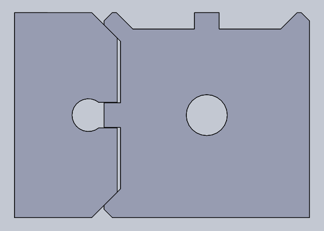
Also here is how I am leaning in terms of geometry
The tool holders, of which way more are made compared to tool posts are just 1 drilling and 3 milling ops. 1 milling op if I used gang tooling. I'm stealing Harold Halls tool post design for the clamp. Any recommendations on tool steel for the retaining piston, cam and maybe the toolpost? Probably the tool post will end up as mild steel, HH used EN1A for all parts I think, but I am curious as to what a more industrial grade post would use. I could for see a hardened cam and piston might be worthwhile even in a hobby environment though. |
| Clive Foster | 10/08/2017 01:41:00 |
| 3630 forum posts 128 photos | Rainbows Thats an excellent picture of the Holbrook lever locking 4 way tool post I was referring to. Where-ever did you find it? The one I have is tiny. Its a clever system. Lifting the lever releases a cam locking system so the post can rotate. There is a nice pair of face spline plates underneath so the post angle through which the post is turned repeats very accurately. Obviously limited to the number of splines. OK thats a common system on British lathes but usually held down with a fixed handled nut that has to be unwound a few turns before the tool post can be lifted over the splines and turned. The Holbrook lever is clearly faster. I'm surprised they never went a step further by fitting some sort of key or bayonet ring to the base of the central "bolt" so it could be withdrawn from the topside and 4 way tool block by releasing the locking cam and turning it through a suitable angle. Seems quite practical if things were arranged so that putting the lever into the straight up position released the tool block for rotation and flipping right over allowed the central "bolt" to be unlatched. Certainly neater than my rotating centre pillar concept. Yes, by tool blocks I do mean simple lump of metal with one, or more, slots for tools bolted straight down to the slide. I've always felt that if such blocks can be made so as to interchange easily with arrangements made to set the tool height off the machine by direct measurement you end up with a system pretty much as effective as a proper QC system but much easier to make. Given a decent collection of sorted shims its no great trouble to set tool heights. Having roughly laid out a system I never got round to trying it as a couple of too good to miss lathe deals netted me a pair of Dickson systems with a good start on enough tool holders. Shimmed the post up on one lathe so tool holders fit both without adjustment. Your geometry will be good being effectively that of a Webster Whitcombe lathe bed. Need to work hard to keep everything parallel and the angles right for decently wide contact areas. Best to make all the holders you will ever need at one setting as the geometry is a lot less tolerant than a Dickson. Nice job for horizontal milling machine if you can get cutters with matched angles. EN1A is a leaded free machining steel. Lovely finish but a bit weak and a bit soft for tooling. Our American friends would probably go for SAE 4140 pre hard which, I understand is pretty decent stuff and still machines well. Gawd knows what you'd get over here if you wanted some. EN19 / 709M40 / 708M40 are supposed to be close equivalents to plain 4140 and EN16 / 605M36 is similar. Have around 150 mm ruling section in R range hardness which should be adequate. Trouble is finding good material in small quantities. I've had some right dross which was very difficult to machine. Rather than harden I'd try and find EN19, EN16 or equivalent in T range. Rulling section about 65 mm which should be more than adequate. I don't trust EN24, 817M40, SAE 4340 even though it can be found in V range at useful sizes. Clive
Edited By Clive Foster on 10/08/2017 01:41:46 Edited By Clive Foster on 10/08/2017 01:43:16 |
| Rainbows | 10/08/2017 13:17:34 |
| 658 forum posts 236 photos | Pic taken from http://www.lathes.co.uk/holbrook/page4.html
The cam is kinda interesting, I might make something like it for the minilathe, the current screw has a tendency to bind shut and need hitting to loosen. Once loose it only takes a quarter turn or something to rotate the tool. I imagine you could coordinate drill some small divets to receive a sprung loaded ball bearing as a easier to make face spline.
I think DROs killed the potential for the block system. Now you have to pick up your offset for each tool change where a quick change you could set all at once at keep em until you move the toolpost. If you had some way of locating the post very accurately it would regain its use but then you have made a weird looking QCTP again. I do have a small capstan which I am going to restore... at some point... at least thats what I tell myself. But your block idea could well suit it if I build a wide cross slide. See how well I can make an interrupted thread work at the same time.
Got a double 45 / 90 degree horizontal cutter lined up. Plan is to blast out 2 500mm long blanks, give me 40 holders for the mini lathe. I am considering making an aluminium tool post in the same set up to use as a lap on the tool post. If I were using a vertical mill with a tilted head I would have a lot more worries about accuracy. As is I think I can get it done pretty simply though. A pre-hardened steel would be ideal but not really sure what counts. I think the T in EN24T makes it prehard? |
| Clive Foster | 10/08/2017 13:55:20 |
| 3630 forum posts 128 photos | Rianbows Apologies for further thread drift but, on further reflection, it appears quite easy to fit a detachable Holbrook style lever lock system to the top of a tool post stud. This would make the interchangeable block system a serious, far simpler to make, alternative to Dickson or other QC systems. Consider a suitably thick and coarsely splined, four should do, ring attached to the top of the tool post stud an appropriate distance above the tool block top face. The cam locking assembly is carried on a sleeve internally splined to match the top ring. In use the locking assembly would be dropped over the top ring with the lever in the unlocked position and turned so that the male spline projections on the ring are in line with the corresponding projections on the female sleeve. Moving the lever to the locking position brings the projections into contact forcing the cam down to securely hold the block in place. Reverse to remove. In practice some form of rotational indexing device on the tool block would be desirable. For larger machinery, like mine, there is room for a baseplate with a simple ring of holes into which a manual push rod, as commonly found on proper Dickson systems, could be engaged. On smaller machines vertical space is limited so a horizontal rod engaging holes in a ring on the stud would be more appropriate as still permitting decent baseplate thickness and reasonable slot depth whilst maintaining direct contact to the top slide surface. Horizontal pin indexing is only practical for single or two slot blocks tho'. Manual pin in hole allows any intermediate position to be used, which is not possible with fixed spline plates. If a top hat shaped thrust collar is interposed between block and locking cam there is essentially no requirement for any abnormal precision of manufacture. Any variation in block heights being easily measured and accommodated by adjusting the thickness of its thrust collar. Adequate single and twin slot tool post blocks can be made by gluing and screwing stock plate and bar sections together avoiding heavy machining. If the female splined sleeve is tricky then the linear motion folk use six spline sleeves on matching rods. Sleeves around an inch long should be suitable and can readily be got in appropriate sizes. Albeit a bit costly. An adequately matching male ring can be produced by hand. Still have to sort your shims and set up a tool height measuring device on the bench. But dial gauges or display on a stick depth gauges are pretty cheap now. Clive. |
| thaiguzzi | 10/08/2017 14:17:04 |
 704 forum posts 131 photos |
|
| thaiguzzi | 10/08/2017 14:19:55 |
704 forum posts 131 photos | 5 holders there. Nasty flame cut steel. All angles AND t slot work done on the shaper.
|
| Clive Foster | 10/08/2017 14:25:22 |
| 3630 forum posts 128 photos | Yup Q, R, S, T, U, V are actually tensile ranges but they correlate well with hardness for the stronger common steels like EN16, EN 19, EN 24 and equivalents. Expect Brinell hardnesses of around 200 for Q, 225 for R, 250 for S, 280 for T, 300 for U and 320 for V all ± 20% or so. But its very variable with considerable overlap and what you actually get depends a lot on material size too. All these materials have a ruling section or maximum diameter for any given tensile range. Higher ranges mean smaller diameter. Its something of a minefield especially if ordering off EN numbers as what you get is almost invariably based on properties, usually just tensile range, not composition. Can be a nasty shock sometimes when you put a tool to it. Use the M series numbers and you should get the right composition so it should behave as expected. EN24 / 817M40 is well known for occasional inexplicable brittle fractures in T and above tensile ranges. Great stuff if properly heat treated on appropriately designed components but I'd be chary about small quantities as it comes form the mill. Still about the cheapest way to get to V range and above in reasonable sections, say 30 mm or so, but your heat treater needs to know exactly what he is doing. Clive. |
| IanT | 10/08/2017 14:42:17 |
| 2147 forum posts 222 photos | I don't want to take this too far off-topic either but Clive mentioned "Tool Blocks" I had an 'economy' QCTH mounted on my small 2.5" EW but found there was often excessive tool overhang and that it also restricted the effective cross-slide movement. The tool-holders did not suit my preferred 3/16" tooling at all well and are quite expensive if you need more than a few. I spent some time looking at the alternatives for a small lathe - and came across a set of articles by Dr RM Rose (Simple Toolholders - ME 3rd Nov 1972). I've made six tool blocks for brass (about 2-3 hours work - and I'm not that quick) to Dr Roses design. They were made to take 3/16" tools and to be (to some extent) inter-changeable between the EW and the S7. They work very well, with no unnecessary tool overhang and are very simple to make. I'm currently looking at 'block-registration" - which will be some form of 3-point locator on the main body to make tool re-location easy. Once I've sorted that out, I intend to make more holders for both general and more specialist tooling - as well as the set of 'work' holders he suggests (mine will be in metric steps though). I mention this because it seems to be the norm these days to go for a QCTH system but there are other simpler and less expensive alternatives that may be a better choice for some... Regards, IanT |
| Rainbows | 10/08/2017 21:42:56 |
| 658 forum posts 236 photos | An economy QCTP being once of those all aluminium ones that are £25 on ebay? Impulse bought one for the mini lathe, yet to put it on though. Through the privilege of having a milling machine to make it a QCTP seems a no brainer to me. Buying 50mm sq stock for each tool holder would probably rack up a modest expense compared to 50x25mm flat. If it were a choice between the square stock and a £80 something tool post though I would probably avoid the QCTP. I do have an idea of making a gibraltar tool post for the keighley using a 50lb cast iron weight for those heavy cuts. Will probably make that then the QCTP since all measurements are low tolerance.
And I envy the ability for shaper tooling to be made with a bench grinder. Replaced the T slot design with the circular hole on account of the expense of small T slot cutters. |


Please login to post a reply.
Magazine Locator
Want the latest issue of Model Engineer or Model Engineers' Workshop? Use our magazine locator links to find your nearest stockist!
Sign up to our Newsletter
Sign up to our newsletter and get a free digital issue.
You can unsubscribe at anytime. View our privacy policy at www.mortons.co.uk/privacy
Latest Forum Posts
- hemingway ball turner
04/07/2025 14:40:26 - *Oct 2023: FORUM MIGRATION TIMELINE*
05/10/2023 07:57:11 - Making ER11 collet chuck
05/10/2023 07:56:24 - What did you do today? 2023
05/10/2023 07:25:01 - Orrery
05/10/2023 06:00:41 - Wera hand-tools
05/10/2023 05:47:07 - New member
05/10/2023 04:40:11 - Problems with external pot on at1 vfd
05/10/2023 00:06:32 - Drain plug
04/10/2023 23:36:17 - digi phase converter for 10 machines.....
04/10/2023 23:13:48 - More Latest Posts...
- View All Topics
Support Our Partners


Shopping Partners
Subscription Offer

Latest "For Sale" Ads
- Reeves** - Rebuilt Royal Scot by Martin Evans
by John Broughton
£300.00 - BRITANNIA 5" GAUGE James Perrier
by Jon Seabright 1
£2,500.00 - Drill Grinder - for restoration
by Nigel Graham 2
£0.00 - WARCO WM18 MILLING MACHINE
by Alex Chudley
£1,200.00 - MYFORD SUPER 7 LATHE
by Alex Chudley
£2,000.00 - More "For Sale" Ads...
Latest "Wanted" Ads
- D1-3 backplate
by Michael Horley
Price Not Specified - fixed steady for a Colchester bantam mark1 800
by George Jervis
Price Not Specified - lbsc pansy
by JACK SIDEBOTHAM
Price Not Specified - Pratt Burnerd multifit chuck key.
by Tim Riome
Price Not Specified - BANDSAW BLADE WELDER
by HUGH
Price Not Specified - More "Wanted" Ads...
Get In Touch!
Do you want to contact the Model Engineer and Model Engineers' Workshop team?
You can contact us by phone, mail or email about the magazines including becoming a contributor, submitting reader's letters or making queries about articles. You can also get in touch about this website, advertising or other general issues.
Click THIS LINK for full contact details.
For subscription issues please see THIS LINK.
Digital Back Issues


Donate

 Register
 Log-in
Model Engineer Magazine
- Percival Marshall
- M.E. History
- LittleLEC
- M.E. Clock

ME Workshop
- An Adcock
- & Shipley
- Horizontal
- Mill

Subscribe Now
- Great savings
- Delivered to your door

Pre-order your copy!
- Delivered to your doorstep!
- Free UK delivery!
All Forum Topics > General Questions > Making a Dickson style QCTP