Member postings for Richard Parsons
Here is a list of all the postings Richard Parsons has made in our forums. Click on a thread name to jump to the thread.
| Thread: New technology in Model Engineers Workshop |
| 01/07/2011 18:03:00 |
John McNamara
Thanks for your reverse polish notation - You've met them! I have PM-ed you so your 'My Messages are 'flashing'
Regards
Dick Parsons |
| Thread: Super Glue & Balance Springs |
| 01/07/2011 17:42:20 |
Ian that tip is very useful.
Thanks
Dick |
| 01/07/2011 07:23:45 |
Sam You are trying to wind a coil spring from a guitar string. This guitar string has been tensioned, hardened and tempered to set it into its shape –straight. To make it into a coil spring you have to do one of few things. The first possibility is to undo all of the treatment and return it to its original soft state. To do this I would put the spring into an airtight metal (steel) container which is packed with (well riddled –to get rid of any combustible materials) ashes from a wood fire. (No you cannot use those ‘Ashes’ - we Poms have got them - for a time). I would then put the container into the back of a fire for a few days. Use the now softened wire to wind your spring. You will then have to harden and re-temper the finished product. The second method and you may have to use this technique with the first method. Is to reduce the mandrel size so that you overcome the modulus of elasticity of the guitar spring and deform it so to give it a ‘permanent set’ to the radius you want. Your problem here is that a guitar spring is made to stay straight. There is a third possibility which is to buy the finished product. I would H.S. Walsh (usual disclaimer). You can find them here. Have a look at the clock materials. You can Buy 72 of them for about 7.50 sterling and at 0.03 Kg the p&p to Oz will not be all that great. Fourthly you cold machine up a sleeve which just slips over the former and the wire. Make a slot along its length. When you have wound your coil -keeping the tension on- slip the sleeve over the lot to hold everything in place. What you do next I have no idea! Finally try google for ‘Spring Wire suppliers’, someone might send you a sample. Good Luck Dick |
| Thread: Planers |
| 30/06/2011 14:18:20 |
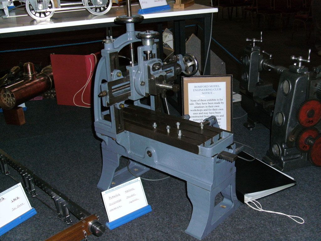
John I you put some magnification on to the image there is a notice which says that it and other tools are not for sale. In the background is a set of Silversmiths sized rolls. The book beside it looks like an ‘A4’ ring book. This gives a work surface of some 12”- 18” (305mm – 458mm) by 6” to 8” (152mm – 208mm) wide. The rack looks about 1” (25.4mm) wide. This machine can ‘Graunch off’ 1/16” deep cuts in bronze. It would be big enough to surface the valve chests of a 5” locomotive. With a suitable gear box containing some ‘jiggery-pokery’ for automatic reverse you would have a nice little power driven table top machine. The base and the slide are both dead ringers for Epoxy Cement construction. http://www.model-engineer.co.uk/forums/postings.asp?th=51617 There was a foundry here but the Hungarians required to make their own drawings and patterns for a 3 ½” railway wagon wheel that I wanted 6 off. The pattern was ‘not metric’. Neither was mine except that you could measure its dimensions in metric. The Hungarians believe that all foreigners are naïve and stupid. The foundary, all the metal in it and even the tin roofs on the on the toilets have all gone. As I want to make one for myself I think Epoxy Cement technique is the only way. I had totally forgotten about planers. There was one in the Heavy Machine shop in one place I worked. It was used to machine the base castings of the machines we made. It was some 10 meters long, with a 7 meter stroke. The machinist sat beside the clapper box over 2 meters off the ground. It also had its own cranes etc for lifting the spanners used on the holdfasts. _Paul_ why not make one yourself . My guestimate that the main base would only take a couple of weeks from drawings to finished casting. Regards Dick Edited By Richard Parsons on 30/06/2011 14:20:24 |
| Thread: A shaping machine in epoxy concrete |
| 27/06/2011 12:14:12 |
I would like to make a little point. I live in Hungary a place which has been nearly de-industrialised. Three or four years ago a number of ‘Oriental Gentlemen’ appeared in the country with suitcases of cash. If there is one thing a Hungarian cannot resist is a suitcase full of cash, especially if the only paperwork wanted is a ‘Chop’ against a weight in a book full of Chinese writing. The country was almost swept clean of anything metallic. It is still going on. If we have a good thunder storm and the power fails, everyone is watching their local overhead feeders to see they do not ‘vanish’. All you can get now is ‘structural section’ steel, which is all the ‘stock holders’ hold. If 75 to 80% of the bulk of my machine is this stuff it is well worth the trouble. I think there is a boat building outfit (in the middle of the great plains! ) who I am going visit to next week. All I want is an Epoxy supplier. Bringing metal in from the U.K./Germay/Austria etc can be both risky (it tends not to arrive) and very is expensive. This is why I became very excited by the epoxy concrete. Ballast I can get from the dredgers on the Danube (often several tonnes for putting a ‘Crane Splice’ into the end of a mooring wire, or running a ‘long splice’ to salvage a thick rope some idiot has cut. The smaller particles I can get from my Garden - I live in the ‘arany homok’ (the golden sands). This stuff is pre-mixed in particle size and the sun will dry it for me for free. I have just done a particle size analysis and find that the minimum grain size is well over 30 minutes. The analysis is that done by telescope grinders for sizing their ‘Rouge’ polish. You need some clean old jam pots. You dump the raw powder into a jar, and mix it with water. Leave it for about 1 second and decant the water into a second jar without disturbing the sediment. Leave the second jar for 5 seconds and repeat the decanting into another jar. No 2 jar contains the 5 second particles. The process is repeated for lengthening intervals and each jar contains finer particles than the first. I must thank Dias for his U-tube images. These lead me onto here. It shows a miniature Planer and I have found others a bit bigger like the one below. These seem to be about 80% cast iron.
|
| 26/06/2011 17:23:37 |
Many thanks John. My idea for the table was to cast the base of the table in one with the cross traverse carrier and cast in the recesses for the ‘T’ nut slots. I was also going to cast in rows of threaded inserts (which would be tack welded to the Re-bar armature. The strips which form the table top ‘T’ slots would be ‘screwed and glued’ to act as a work surface. I do not actually use ‘T’ nuts I use a modified bolt. I standardise on 8mm for the Myford and 10mm for the mill although I often use 8mm on the mill as well. Most of the armature will be in 6mm re-bar tacked together. I will also have to build a jig to hold at least 3 datum inserts in a fixed position to each other to act as reference points. 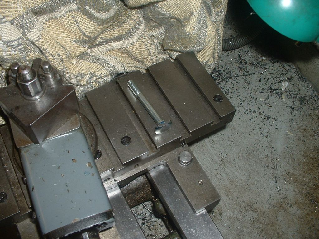 |
| 26/06/2011 08:19:16 |
I have always wanted to get my ‘hooks’ on a machine which would allow me to machine really flat surfaces. I designed a small knee-less horizontal milling machine which was to be fabricated from structural steel and would use SKF (usual disclaimer) linear slides. My local suppliers have minimum order rules which for the products I wanted. I would have had to buy 10 pairs of each size and length of rail and 20 pairs of each of the corresponding bearings. These would have cost a king’s ransom so that idea was binned. I have a rule never to publish anything I have not made and know works, so I kept very quiet about the thing. That is how things stayed until I found an article on the web entitled ‘A Small Shaping Machine by Mr E.H. Knight. It was published in the Model Engineer 5th October 1952. It was totally fabricated without welding or brazing. This article can be found here. I looked at the article and thought ‘this is a dead ringer’ for the epoxy concrete technique used by John McNamara the thread on this website called New Technology in the Model Engineers workshop The original specification by Mr E.H. Knight is as follows Table size 4 ¾” (120.65mm) by 4 ¼” (107.95mm) Stroke 3” (76.2mm) Cross feed 4” (101.6mm) Tool down feed movement ½” (12.7mm) Unfortunately he gives no direct indication of the maximum daylight that is from the bottom of the ram to the top of the base plate. From Mr. Knight’s drawings looks to be around 2” (50.8mm) All of Mr Knight’s slide ways are 60/30° mitres with no gib-strips. I think that the dimensions given are too small for my use. I want to build small ICs as I can get the full-ish kit of materials from the U.K. My specification would be Table size 8 ¾” (222.25mm) by 8” (203.2mm) Stroke 6” (152.0mm) Cross feed 6” (152.0mm) as measured from the centre of the ram Daylight 6” (152.0mm) Tool down feed movement minimum 2” (50.8mm) Since I am scaling Mr. Knight’s sized up by a half I am going to increase the thickness by 1.5 times. So a ¼” will become 3/8” and using John McNamara figures from his contribution in “New technology in Model Engineers Workshop” I will thicken the material by a factor of 4 where needed. This will be in the base thickness, the cross traverse and the ram carrier will be cast in epoxy concrete. The ram and clapper box assemblies will be in steel as will the top of the base plate. I want to power the machine as I have no liking to pull the ‘punishment leaver’ for several hours. I have a 1/8HP Squirrel Cage motor and would not like to take more than 40-60 thou (1-1.5mm) cuts. Mr Knight’s machine has no automatic cross feed, mine will have. This will be a ratchet wheel which turns the cross feed screw through a key-way. The feed pawl will be at the rear of the ram and will engage the ratchet on the return stroke. Its position on the ram will determine the amount of feed. The slide-ways, I have an idea about them which I will reveal later once I have sorted out a material. I would love to hear comments and helpful advice. |
| Thread: Tank Tracks |
| 25/06/2011 08:40:11 |
Stub the contraption you want is “a universal carrier”. Long ago (and now far away) there was one stuck in a ditch for many months until ‘Ole Farmer’ hauled it out with a crawler tractor to get at the petrol left in its tanks. Local copper went ‘round the twiddle’ because it was blocking the road. Eventually some folk came with a Scammel transporter to take it away. They took it away (none too steadily) well it was hot work getting the thing on to the Scammel. And the locals were only too happy to get rid of the dregs of last year’s ‘Zider’ for 1/2d (real money) for a gallon or so of the stuff. They seemed quite sober but this tackle induced a narcosis and sort of paralysed their muscles –they seemed and were wide awake but nothing (arms, legs etc) worked. That were, as the locals said, a drop of ‘good’. Now you want to make a working track. On this one I would ‘cheat’. I would probably cast the guidance lugs (the things which stop the tracks from derailing from the bogie wheels) as pairs and the tread plates (the bits that run on the road) in a hard low melting alloy. I would go ‘skip diving’ for bale/case strapping (not the metal ones but the sort of stringy stuff). I would hunt up an ‘elastoma’ type resin (try ‘Strand Glass usual disclaimer) and build the things that way. I will try and make a sketch for you and load it. Rdgs Dick |
| Thread: Whittle V8 - Crankshaft |
| 24/06/2011 10:38:01 |
Steve have a look at the gear train which drives the cam shaft and work out the direction of rotation. using that work out the order of the valve events
regds
Dick |
| Thread: Sine Tables, Sine bars and calculations |
| 22/06/2011 09:43:07 |
John - I can foresee a sort of problem. The small pins that you point out may be there to stop the big ball from over rotating so you will not get the small balls up on the table. Hum Ho |
| Thread: Whittle V8 - Crankshaft |
| 22/06/2011 09:33:01 |
Oh bother, I have just realised that your journals are offset so you cannot use steadies in the way I did as you have over 5/16” you could rig up a single steady. Dick |
| 22/06/2011 09:06:25 |
Steve I would make several tubes. And only use two at a time. One is a very short one, one very long for the first journal. Then a longer one and cut the very long one down for the second and so on. As you have only 0.34 mm to go (0.17 mm cut -about 7 thou in real money) I would set up a filing rest and take this off with some nice sharp pillar files. I also used the Fixed Steady on the longest part of the tube and a Travelling Steady on the other side of the journal being worked on. Or do as I did make, two/three extra wide fingers for the steady about 20- 25 mm long to straddle the cut. If you get vibration then add some lead bands to change the thing’s resonance and that of the tool.
I would leave the webs alone until you have finished the journals as milling them down will leave gaps and reduce the stiffeniing effect of the tubes Hope it helps Dick PS Clock makers often use files in the lathe. Edited By Richard Parsons on 22/06/2011 09:17:10 Edited By Richard Parsons on 22/06/2011 09:23:07 |
| 21/06/2011 15:43:24 |
I have had to machine a similar item in about 1979. It was not a crankshaft. How I did it was to machine up two pipes which were a nice snug fit onto the bits you will call ’webs’. These support the parts not being machined. I made two attachments to the fixed steady well wider than the bit I was machining. These supported the pipes. And away I went very sharp tool and very fine cuts and a slow feed. Job done! By the way the tailstock end of the pipes ran in a ball race. You might try a Jacot tool and a set off pivot files instead. All the Best Dick |
| Thread: BA Screws to Metric Screws |
| 20/06/2011 18:40:21 |
Armando in a word yes! If you use The American UNC/UNF threads you need inch size spanners which are in fractions of an inch AF (across the flats). If you use ISO metrics you use Metric spanners. Though some will coincide (just about) with the American (13mm is ½” BA spanners are special to the BA range. A No 2 BA spanner will fit the No 2 BA thread with a standard head on it. It is the thread No which determines the head size (and the spanner). You can however buy/make ‘Specials’ these are BA threads with a size (or two) smaller head. The basis of the BA system is that the thread angle is constant at 47 ½ ° but the pitch of each size is 90% of the previous size. The largest is no 0 BA which is 6mm diameter 1mm pitch. The pitch of No 1 BA is therefore 0.9mm, 2Ba is 90% of 0.9 which is 0.81 and so on down to No 24 BA which is the smallest round about 0.25 mm stock bar size. You will find the Metric tapping and clearing sizes drills for all BAs in metric here http://www.clag.org.uk/bascrew.html, but he only goes down to No 16 BA It is a good idea to select a Tapping size so for a No 4 BA tapping size I tend to choose not a 3.0mm but a 3.1 mm or even a 3.2mm drill. It is easier than trying to dig out a broken tap! BA means The British Association for the Advancement of Science who designed the threads in co-operation with the Swiss Watchmakers’ association round about the year 1900. From 6mm down to 1mm there are 12 sizes in Metrics there are some 20 sizes for the same range. You pay your money and take your choice. Regards Dick Parsons |
| Thread: Gas burner |
| 20/06/2011 18:02:07 |
It looks as if you are getting No secondary air into the 19mm tube or no draft through it. A short bit of pipe in the chimney with a little bit of pipe blowing up it with a foot pump. There is a sketch of this thing in the book of the Titch by LBSC. It induces a draft through the boiler.
Rdgs Dick |
| Thread: Warco Mill Identification |
| 20/06/2011 13:18:50 |
Graham, The thing is worth only what you can afford and are prepared to pay for it. How worn and loose are the slides? How much back-lash in the feed screws How bad are the signs of a ‘struggle’ are showing on the various nuts and bolts (look at those which hold the motor unit and gear box to the pillar. Remember and ask about the large fibre gear. Ask him to take the motor ff and have a good look inside at the gear. Are there any signs of the gear being ‘munched away’? Look at the oil and feel it between your thumb and finger. Do you feel any metal there? Any bits missing? What fittings and tools come with it? Have a chat with Warco. As to value make an offer, they are quite robust machines. I have had and used mine for about 18 years. Best regards Dick |
| 19/06/2011 17:22:32 |
Mike i agree with you, Yes it is a VHM and is the same as mine. The biggest worry (and problem) was the Fibre gear wheel which was driven by the motor pinion and turned the main gear box. I chewed up two of them. The motor pinion was something like 24DP (calculated) and the fibre gear was about 26.4 (something) DP (calculated). I do not know what Warco did about them as after the second failure in about 10 months i was a might fed up. So in the end I fixed the joker. I made a plate with a spindle (to replace the Motor) with a slot in it to get a telescope gauge in. I averaged out a dozen or so readings. I then wrote a program to search all the DPs and Modules in a well known gear catalogue (Helical section) for the best fit at about the right ratio. Bought the cogs, fitted them job done. Ok she is a bit slower than the original andshe used to ‘ring’ a bit but now 18 years later she purrs like an old fat cat in front of the fire on a cold winter’s day. |
| Thread: BA Screws to Metric Screws |
| 18/06/2011 16:07:49 |
JasonB - BAs metric! - Do not you believe it . Just before I left old England I went to a place I knew which sold BA sizes. His entire stock had been impounded by some local idiot (some sort of Trading Standard Officer) who had ruled (on the basis of a declaration by the BSI) BAs are inch - so you cannot sell them – that is official! You and I know that the base threads (O BA) is 6mm dia 1mmpitch etc, but they are still inch. I suppose that 19mm which is within 0.05mm of ¾” is also ‘inch’. |
| Thread: Super Glue & Balance Springs |
| 15/06/2011 18:16:26 |
Hi Sam, When clock/watch makers talk of shellac it is not the same tackle that French Polishers use. A clock/watch maker buys the stuff as a stick (like sealing wax) which he heats up to melt it and use hot. These days I use a hot glue gun. Spring making is quite an art/skill. If you are into clocks get yourself a copy of “Watch & Clock makers’ Handbook Dictionary and Guide by Britten. ISBN 1 85149 192 9. Britten tells you to get spring wire in its soft form, Wind your spring, (there are a good few pages in Britten on doing that) then you harden your spring Britten also has a long description of this. If you are getting ‘spring wire’ in its soft state the supplier will tell you about both the hardening and tempering temperatures. Finally Sam There are composite carbon fibre springs Rgds Dick |
| Thread: Steam Boat Ban |
| 15/06/2011 13:09:47 |
I once asked a City Safety Manager why he had closed a foot path by the river. His reply was “Because I can”! I pointed out that the path was a grant to the citizens made by the Benedictine monks in 12 hundred and how’s your father. It the gift was made In exchange for closing the highway made by the King (Stephan of Blois). The pathway had to be there to allow the citizens to get to the river to catch fresh fish which was a right they (the citizens) had been given by the king of Wessex (Alfred). His reply was to the effect that they cannot fish anymore! |
 etc. If you use BSW or BSF threads you need a Whitworth set of spanners.
 Magazine Locator
Want the latest issue of Model Engineer or Model Engineers' Workshop? Use our magazine locator links to find your nearest stockist!
Sign up to our Newsletter
Sign up to our newsletter and get a free digital issue.
You can unsubscribe at anytime. View our privacy policy at www.mortons.co.uk/privacy
Latest Forum Posts
- *Oct 2023: FORUM MIGRATION TIMELINE*
05/10/2023 07:57:11 - Making ER11 collet chuck
05/10/2023 07:56:24 - What did you do today? 2023
05/10/2023 07:25:01 - Orrery
05/10/2023 06:00:41 - Wera hand-tools
05/10/2023 05:47:07 - New member
05/10/2023 04:40:11 - Problems with external pot on at1 vfd
05/10/2023 00:06:32 - Drain plug
04/10/2023 23:36:17 - digi phase converter for 10 machines.....
04/10/2023 23:13:48 - Winter Storage Of Locomotives
04/10/2023 21:02:11 - More Latest Posts...
- View All Topics
Support Our Partners


Shopping Partners
Subscription Offer

Latest "For Sale" Ads
- Reeves** - Rebuilt Royal Scot by Martin Evans
by John Broughton
£300.00 - BRITANNIA 5" GAUGE James Perrier
by Jon Seabright 1
£2,500.00 - Drill Grinder - for restoration
by Nigel Graham 2
£0.00 - WARCO WM18 MILLING MACHINE
by Alex Chudley
£1,200.00 - MYFORD SUPER 7 LATHE
by Alex Chudley
£2,000.00 - More "For Sale" Ads...
Latest "Wanted" Ads
- D1-3 backplate
by Michael Horley
Price Not Specified - fixed steady for a Colchester bantam mark1 800
by George Jervis
Price Not Specified - lbsc pansy
by JACK SIDEBOTHAM
Price Not Specified - Pratt Burnerd multifit chuck key.
by Tim Riome
Price Not Specified - BANDSAW BLADE WELDER
by HUGH
Price Not Specified - More "Wanted" Ads...
Get In Touch!
Do you want to contact the Model Engineer and Model Engineers' Workshop team?
You can contact us by phone, mail or email about the magazines including becoming a contributor, submitting reader's letters or making queries about articles. You can also get in touch about this website, advertising or other general issues.
Click THIS LINK for full contact details.
For subscription issues please see THIS LINK.
Digital Back Issues


Donate

 Register
 Log-in
Model Engineer Magazine
- Percival Marshall
- M.E. History
- LittleLEC
- M.E. Clock

ME Workshop
- An Adcock
- & Shipley
- Horizontal
- Mill

Subscribe Now
- Great savings
- Delivered to your door

Pre-order your copy!
- Delivered to your doorstep!
- Free UK delivery!